★ TRUSTED BY 321,897+ PROFESSIONALS WORLDWIDE
🏒
Trusted Business
Verified & Licensed
πŸ›‘οΈ
Virus Free Files
100% Safe Downloads
πŸ”’
Secure Payment
SSL Protected
⚑
Instant Delivery
Available Immediately
Sale!

Komatsu PC160LC-7E0 PC180LC-7E0 PC180NLC-7E0 Excavator Shop Manual – PDF Download

Original price was: $39.95.Current price is: $23.95.

Complete Komatsu shop manual for PC160LC-7E0, PC180LC-7E0, and PC180NLC-7E0 hydraulic excavators (serial K45001 and up). Covers specifications, structure and function, testing and adjusting, troubleshooting by failure code, disassembly and assembly, hydraulic and electrical circuit diagrams, standard value tables, and more. 958-page PDF in English.

⚑
Instant PDF Download
Available immediately
πŸ’Ύ
Save to Your Device
Download & keep forever
πŸ›‘οΈ
Antivirus Scanned
100% virus-free
🌍
Trusted Worldwide
175,000+ customers

Description

Komatsu PC160LC-7E0, PC180LC-7E0, and PC180NLC-7E0 Excavator Shop Manual

This Komatsu PC160LC-7E0 PC180LC-7E0 PC180NLC-7E0 Excavator Shop Manual is the complete workshop reference for three 7E0-series hydraulic excavators, covering serial numbers K45001 and up. It is a 958-page PDF written in English and published under document number UEN01892-04, with individual sections carrying their own form numbers (UEN01894 through UEN02454, plus UEN01912 and UEN01913 for diagrams). Whether you are servicing a PC160LC-7E0, diagnosing a fault on a PC180LC-7E0, or rebuilding components on a PC180NLC-7E0, this Komatsu shop manual gives you the procedures, values, and illustrations you need in one searchable document.

File Details

  • Manual type: Shop Manual (complete workshop service and repair manual)
  • Brand: Komatsu
  • Models covered: PC160LC-7E0, PC180LC-7E0, PC180NLC-7E0
  • Serial numbers: K45001 and up (all three models)
  • Language: English
  • Page count: 958
  • File format: PDF
  • Document number: UEN01892-04 (main binder); section form numbers UEN01894-04 through UEN02454-00, UEN01912-01, UEN01913-02
  • Publication dates shown: 2007 and 2008 (individual sections dated 09-07 and 06-08)
  • Engine model: SAA4D107E-1

Chapters Covered

The manual is organized into the following top-level sections, each containing detailed sub-sections:

  • 00 Index and Foreword β€” Composition of shop manual, table of contents, safety notice, how to read the shop manual, explanation of terms for maintenance standard, handling electric equipment and hydraulic components, how to read electric wire code, precautions when carrying out operation, method of disassembling and connecting push-pull type coupler, standard tightening torque table, conversion table
  • 01 Specification β€” Specification dimension drawings, specifications, weight table, table of fuel, coolant and lubricants
  • 10 Structure, Function and Maintenance Standard
    • Engine and cooling system β€” Engine related parts, radiator, oil cooler, aftercooler and fuel cooler
    • Power train system β€” Power train, swing circle, swing machinery, final drive, sprocket
    • Undercarriage and frame β€” Track frame, recoil spring, idler, carrier roller, track roller, track shoe
    • Hydraulic system, Part 1 β€” Hydraulic equipment layout, hydraulic tank, hydraulic pump
    • Hydraulic system, Part 2 β€” Control valve, CLSS, functions and operation by valve, hydraulic drift prevention valve
    • Hydraulic system, Part 3 β€” PPC valve, solenoid valve, accumulator, return oil filter, centre swivel joint, travel motor, swing motor, attachment circuit selector valve, quick coupler control valve, hydraulic cylinder
    • Work equipment β€” Work equipment, 2-piece boom, dimensions of components
    • Cab and its attachments β€” Air conditioner piping
    • Electrical system β€” Engine control, electronic control system, monitor system, sensor, KOMTRAX terminal system
  • 20 Standard Value Table β€” Standard service value table for engine, standard value table for chassis related parts
  • 30 Testing and Adjusting
    • Testing and adjusting, Part 1 β€” Tools, measuring engine speed, intake air pressure, exhaust gas colour, valve clearance, compression pressure, blow-by pressure, engine oil pressure, fuel system procedures, air conditioner belt tension, fan belt replacement
    • Testing and adjusting, Part 2 β€” Swing circle bearing clearance, track shoe tension, oil pressure in work equipment/swing/travel circuits, control circuit, pump PC and LS control circuits, solenoid valve output pressure, PPC valve output pressure, travel deviation, oil leakage, bleeding air, diode inspection, mirror adjustment
    • Testing and adjusting, Part 3 β€” Special functions of machine monitor, engine controller voltage circuit, KOMTRAX terminal, electrical system troubleshooting preparation, Pm-clinic service
  • 40 Troubleshooting
    • Failure code table and fuse locations
    • General information on troubleshooting
    • Troubleshooting by failure code, Parts 1–4 (covering AA10NX, AB00KE, B@BAZG through DY2EKB)
    • Troubleshooting of electrical system (E-mode) β€” E-1 through E-32
    • Troubleshooting of hydraulic and mechanical system (H-mode) β€” H-1 through H-29, plus quick coupler
    • Troubleshooting of engine (S-mode) β€” S-1 through S-16
  • 50 Disassembly and Assembly
    • General information β€” How to read manual, list of adhesives, special tool list, sketches of special tools
    • Engine and cooling system β€” Removal/installation of fuel supply pump, fuel injector, front oil seal, rear oil seal, cylinder head, radiator, aftercooler, oil cooler, engine and hydraulic pump assembly, engine hood, fuel tank
    • Power train β€” Travel motor and final drive, swing motor and swing machinery, swing circle
    • Undercarriage and frame β€” Carrier roller, track roller, idler, recoil spring, track shoe, sprocket, revolving frame, counterweight
    • Hydraulic system β€” Centre swivel joint, hydraulic tank, hydraulic pump, control valve, pump input shaft oil seal, work equipment PPC valve, travel PPC valve, hydraulic cylinder, quick coupler valve
    • Work equipment β€” Removal and installation of work equipment assembly
    • Cab and its attachments β€” Operator’s cab, cab glass, front window assembly, floor frame assembly
    • Electrical system β€” Air conditioner compressor, condenser, unit, machine monitor, pump controller, engine controller, KOMTRAX assembly
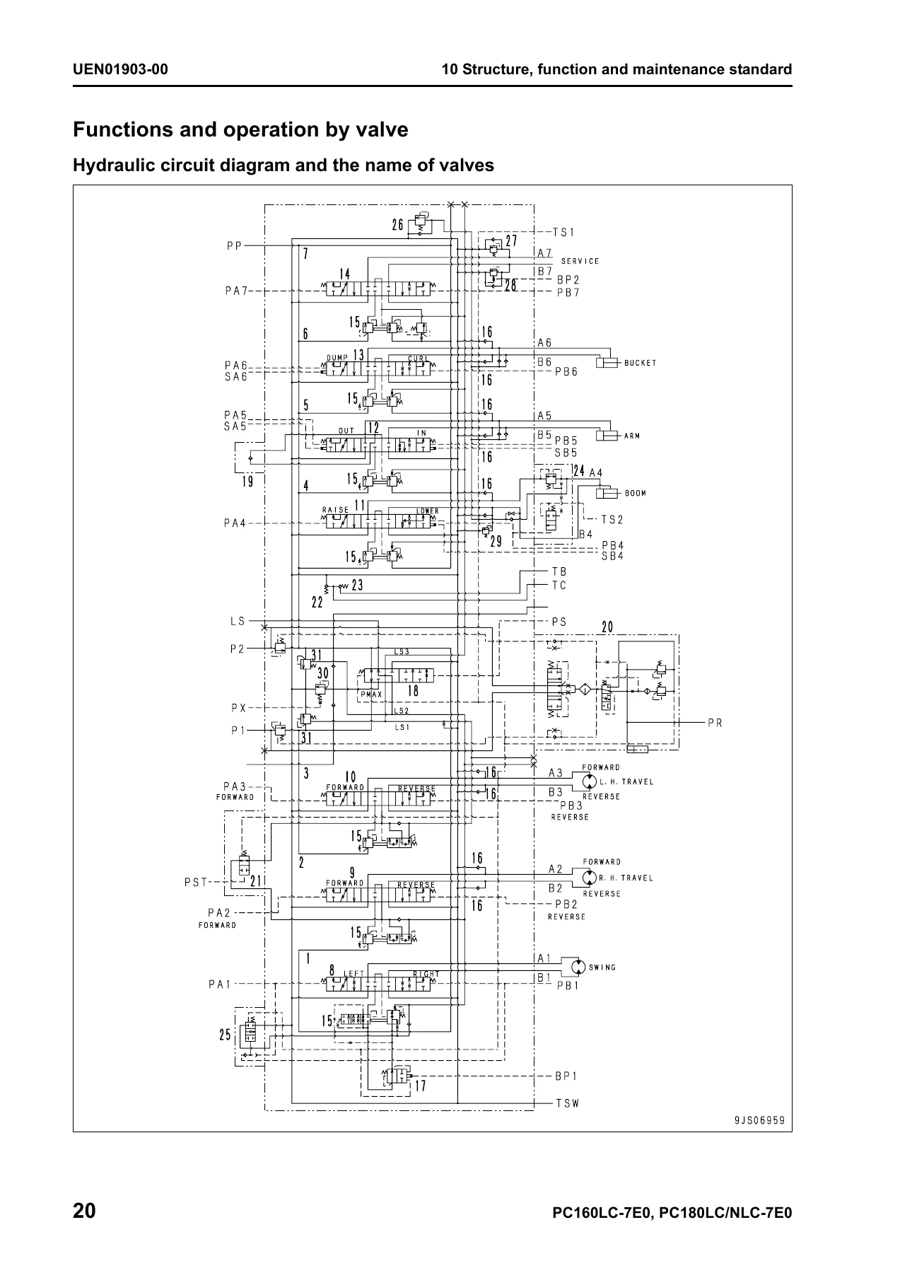
  • 90 Diagrams and Drawings β€” Hydraulic circuit diagram (1/2 and 2/2), electrical circuit diagram (1/5 through 5/5), connector arrangement diagram

This Komatsu PC160LC-7E0 PC180LC-7E0 PC180NLC-7E0 shop manual is far more than a specification sheet. It is the full service documentation set used for these machines, combining the specification and technical data chapter with the structure and function explanation, the standard value table, the complete testing and adjusting procedures, the troubleshooting guides organized by failure code and by symptom (electrical E-mode, hydraulic/mechanical H-mode, and engine S-mode), the disassembly and assembly procedures with torque values and special tool references, and the hydraulic and electrical circuit diagrams. For anyone maintaining or repairing a PC160LC-7E0, PC180LC-7E0, or PC180NLC-7E0 excavator, this Komatsu shop manual covers everything from routine valve clearance adjustment to full component overhaul.

What This Manual Enables You to Do

With this Komatsu PC160LC-7E0 PC180LC-7E0 PC180NLC-7E0 Excavator Shop Manual, you can perform the full range of service work on these machines:

  • Diagnose faults accurately using the failure code table, the E-mode electrical troubleshooting procedures, the H-mode hydraulic and mechanical troubleshooting charts, and the S-mode engine troubleshooting guides.
  • Test and adjust engine speed, intake air pressure, valve clearance, compression pressure, blow-by pressure, oil pressure, fuel pressure, swing circle bearing clearance, track shoe tension, hydraulic circuit pressures, PC and LS control circuit pressures, solenoid valve output pressures, and PPC valve output pressures.
  • Disassemble and reassemble major components including the engine, hydraulic pump, control valve, travel motor, final drive, swing motor, swing machinery, swing circle, hydraulic cylinders, centre swivel joint, and work equipment.
  • Reference correct specifications for hydraulic pressures, torque values, clearances, service limits, and capacities from the standard value table and technical specification sections.
  • Understand how systems work with the structure and function explanations covering the hydraulic pump, control valve, CLSS, LS valve, PC valve, EPC valve, travel motor, swing motor, and electrical control systems.
  • Read and follow circuit diagrams with the hydraulic circuit diagrams and electrical circuit diagrams included in the diagrams and drawings section.
  • Use the machine monitor for monitoring, abnormality records, maintenance records, adjustments, cylinder cut-out, and no-injection cranking with the special functions documentation.
  • Work with KOMTRAX using the terminal system procedures, lamp indications, and troubleshooting information.

Complete PDF Bookmark Tree

Complete Bookmarks

The complete bookmarks in the β€œKomatsu PC160LC-7E0 PC180LC-7E0 PC180NLC-7E0 Excavator Shop Manual – PDF Download” are as follows:

Coverp. 1
00 Index and forewordp. 3
Indexp. 3
Composition of shop manualp. 4
Table of contentsp. 6
00 Index and forewordp. 15
Foreword and general informationp. 15
Safety noticep. 16
How to read the shop manualp. 21
Explanation of terms for maintenance standardp. 23
Handling electric equipment and hydraulic componentp. 25
How to read electric wire codep. 37
Precautions when carrying out operationp. 40
Method of disassembling and connecting push-pull type couplerp. 43
Standard tightening torque tablep. 46
Conversion tablep. 50
01 Specificationp. 57
Specification and technical datap. 57
Specification dimension drawingsp. 58
Specificationsp. 60
Weight tablep. 62
Table of fuel, coolant and lubricantsp. 64
Engine related partsp. 68
Radiator, oil cooler, aftercooler and fuel coolerp. 69
10 Structure, function and maintenance standardp. 67
Engine and cooling systemp. 67
Power trainp. 72
Swing circlep. 73
Swing machineryp. 74
Final drivep. 76
Sprocketp. 78
10 Structure, function and maintenance standardp. 71
Power train systemp. 71
Track frame, recoil springp. 82
Idlerp. 84
Carrier rollerp. 86
Track rollerp. 87
Track shoep. 88
10 Structure, function and maintenance standardp. 81
Undercarriage and framep. 81
Hydraulic equipment layout drawingp. 94
Hydraulic tankp. 96
Hydraulic pumpp. 98
10 Structure, function and maintenance standardp. 93
Hydraulic system, Part 1p. 93
Control valvep. 126
CLSSp. 140
Functions and operation by valvep. 144
Hydraulic drift prevention valvep. 168
10 Structure, function and maintenance standardp. 125
Hydraulic system, Part 2p. 125
Valve controlp. 186
PPC valvep. 187
Solenoid valvep. 204
Accumulatorp. 206
Return oil filterp. 207
Centre swivel jointp. 208
Travel motorp. 209
Swing motorp. 219
Attachment circuit selector valvep. 220
Quick coupler control valvep. 224
Hydraulic cylinderp. 226
10 Structure, function and maintenance standardp. 185
Hydraulic system, Part 3p. 185
Work equipmentp. 230
Work equipment (2 Piece Boom)p. 231
Dimensions of componentsp. 234
10 Structure, function and maintenance standardp. 229
Work equipmentp. 229
Air conditioner pipingp. 240
10 Structure, function and maintenance standardp. 239
Cab and its attachmentsp. 239
Engine controlp. 244
Electronic control systemp. 253
Monitor systemp. 279
Sensorp. 297
KOMTRAX terminal systemp. 300
10 Structure, function and maintenance standardp. 243
Electrical systemp. 243
Standard value table for enginep. 304
Standard value table for chassis related partsp. 305
20 Standard value tablep. 303
Standard service value tablep. 303
30 Testing and adjustingp. 319
Testing and adjusting, Part 1p. 319
Tools for testing, adjusting, and troubleshootingp. 320
Measuring engine speedp. 323
Measuring intake air pressure (boost pressure)p. 324
Checking exhaust gas colourp. 325
Adjusting valve clearancep. 326
Measuring compression pressurep. 328
Measurement of blow-by pressurep. 330
Measuring engine oil pressurep. 331
Handling fuel system partsp. 332
Releasing residual pressure from fuel systemp. 332
Measuring fuel pressurep. 333
Measuring fuel discharge, return and leakagep. 335
Bleeding air from fuel circuitp. 339
Checking fuel circuit for leakagep. 341
Checking and adjusting air conditioner compressor belt tensionp. 342
Replacing the fan beltp. 343
30 Testing and adjustingp. 345
Testing and adjusting, Part 2p. 345
Measurement of clearance in swing circle bearingsp. 346
Checking and adjusting track shoe tensionp. 347
Inspection and adjustment oil pressure in work equipment, swing, and travel circuitsp. 348
Inspection and adjustment of control circuit oil pressurep. 351
Inspection and adjustment of pump PC control circuit oil pressurep. 352
Inspection and adjustment of pump LS control circuit oil pressurep. 355
Measurement of solenoid valve output pressurep. 359
Measurement of PPC valve output pressurep. 362
Adjustment of work equipment and swing PPC valvep. 363
Measuring and adjusting quick coupler control valve output pressurep. 364
Inspection of locations of hydraulic drift of work equipmentp. 365
Testing and adjusting travel deviationp. 367
Release of residual pressure from hydraulic circuitp. 369
Measurement of oil leakagep. 370
Bleeding air from each partp. 372
Inspection procedures for diodep. 374
Adjusting mirrorsp. 375
Special functions of machine monitorp. 380
Handling voltage circuit of engine controllerp. 408
Procedure for turning on KOMTRAX terminalp. 409
Indication by KOMTRAX terminal lampsp. 412
Preparation work for troubleshooting of electrical systemp. 415
30 Testing and adjustingp. 379
Testing and adjusting, Part 3p. 379
Failure code tablep. 424
Fuse locationsp. 427
40 Troubleshootingp. 423
Failure code table and fuse locationsp. 423
40 Troubleshootingp. 431
General information on troubleshootingp. 431
Points to remember when troubleshootingp. 432
Sequence of events in troubleshootingp. 433
Checks before troubleshootingp. 434
Classification and troubleshooting stepsp. 435
Information in troubleshooting tablep. 436
Possible problems and troubleshooting No.p. 438
Wiring table for connector pin numbersp. 441
T-adapter box and T-adapter tablep. 470
40 Troubleshootingp. 475
Troubleshooting by failure code, Part 1p. 475
Failure code [AA10NX] Air cleaner cloggingp. 477
Failure code [AB00KE] Charge voltage lowp. 478
Failure code [B@BAZG] Eng. oil press. lowp. 480
Failure code [B@BAZK] Eng. oil level lowp. 481
Failure code [B@BCNS] Eng. coolant overheatp. 482
Failure code [B@BCZK] Eng. coolant level lowp. 484
Failure code [B@HANS] Hydr oil overheatp. 486
Failure code [CA111] EMC critical internal failurep. 486
Failure code [CA115] Eng Ne and bkup speed sens errorp. 487
Failure code [CA122] Chg air press sensor high errorp. 489
Failure code [CA123] Chg air press sensor low errorp. 491
Failure code [CA131] Throttle sensor high errorp. 493
Failure code [CA132] Throttle sensor low errorp. 495
Failure code [CA144] Coolant temp sens high errorp. 497
Failure code [CA145] Coolant temp sens low errorp. 499
Failure code [CA153] Chg air temp sensor high errorp. 501
Failure code [CA154] Chg air temp sensor low errorp. 503
Failure code [CA155] Chg air temp high speed deratep. 505
Failure code [CA187] Sens supply 2 volt low errorp. 507
Failure code [CA221] Ambient press sens high errorp. 509
Failure code [CA222] Ambient press sens low errorp. 511
Failure code [CA227] Sens supply 2 volt high errorp. 513
Failure code [CA234] Eng. overspeedp. 514
Failure code [CA238] Ne speed sens supply volt errorp. 515
Failure code [CA271] IMV/PCV1 short errorp. 516
Failure code [CA272] IMV/PCV1 open errorp. 517
Failure code [CA322] Inj #1 open/short errorp. 519
Failure code [CA324] Inj #3 open/short errorp. 521
40 Troubleshootingp. 525
Troubleshooting by failure code, Part 2p. 525
Failure code [CA331] Inj #2 open/short errorp. 528
Failure code [CA332] Inj #4 open/short errorp. 530
Failure code [CA342] Calibration code incompatibilityp. 532
Failure code [CA351] Injectors drive circuit errorp. 534
Failure code [CA352] Sens supply 1 volt low errorp. 536
Failure code [CA386] Sens supply 1 volt high errorp. 538
Failure code [CA428] Water in fuel sensor high errorp. 540
Failure code [CA429] Water in fuel sensor low errorp. 542
Failure code [CA435] Eng oil press sw errorp. 544
Failure code [CA441] Engine controller battery voltage low errorp. 546
Failure code [CA442] Engine controller battery voltage high errorp. 548
Failure code [CA449] Rail press very high errorp. 550
Failure code [CA451] Rail press sensor high errorp. 552
Failure code [CA452] Rail press sensor low errorp. 554
Failure code [CA488] Chg air temp high torque deratep. 556
Failure code [CA553] Rail press high errorp. 556
Failure code [CA559] Rail press low errorp. 557
Failure code [CA689] Eng Ne speed sensor errorp. 558
Failure code [CA731] Eng Bkup speed sens phase errorp. 560
Failure code [CA757] All continuous data lost errorp. 562
Failure code [CA778] Eng Bkup speed sensor errorp. 564
Failure code [CA1633] KOMNET Datalink timeout errorp. 566
Failure code [CA2185] Throt sens sup volt high errorp. 568
Failure code [CA2186] Throt sens sup volt low errorp. 569
Failure code [CA2249] Rail press very low errorp. 570
Failure code [CA2311] IMV solenoid errorp. 572
Failure code [CA2555] Grid htr relay volt high errorp. 574
Failure code [CA2556] Grid htr relay volt low errorp. 576
Failure code [D110KB] Battery relay drive S/Cp. 580
Failure code [D196KA] Service return relay disc.p. 582
Failure code [D196KB] Service return relay S/Cp. 584
Failure code [DA22KK] Pump solenoid power low errorp. 586
Failure code [DA25KP] Press. sensor power abnormalityp. 588
Failure code [DA2RMC] Pump comm. abnormalityp. 590
Failure code [DA2SKQ] Model selection abnormalityp. 592
Failure code [DAFRMC] Monitor comm. abnormalityp. 594
Failure code [DGH2KB] Hydr oil sensor shortp. 596
Failure code [DHPAMA] F pump press sensor abnormalityp. 598
Failure code [DHPBMA] R pump press sensor abnormalityp. 600
Failure code [DHSAMA] Sw RH PPC press sen. abnormalityp. 602
Failure code [DHSBMA] Sw LH PPC press sen. abnormalityp. 604
40 Troubleshootingp. 579
Troubleshooting by failure code, Part 3p. 579
Failure code [DW43KA] Travel speed sol. disc.p. 610
Failure code [DW43KB] Travel speed sol. S/Cp. 612
Failure code [DW45KA] Swing brake sol. disc.p. 614
Failure code [DW45KB] Swing brake sol. S/Cp. 618
Failure code [DW91KA] Travel junction sol. disc.p. 620
Failure code [DW91KB] Travel junction sol. S/Cp. 622
Failure code [DWJ0KA] Merge-divider sol. discp. 624
Failure code [DWJ0KB] Merge-divider sol. S/Cp. 626
Failure code [DWK0KA] 2-stage relief sol. disc.p. 628
Failure code [DWK0KB] 2-stage relief sol. S/Cp. 630
Failure code [DXA0KA] PC-EPC sol. disc.p. 632
Failure code [DXA0KB] PC-EPC sol. S/Cp. 634
Failure code [DXE4KA] Service current EPC disc.p. 636
Failure code [DXE4KB] Service current EPC S/Cp. 637
Failure code [DY20KA] Wiper working abnormalityp. 638
Failure code [DY20MA] Wiper parking abnormalityp. 640
Failure code [DY2CKB] Washer drive S/Cp. 642
Failure code [DY2DKB] Wiper drive (for) S/Cp. 644
Failure code [DY2EKB] Wiper drive (rev) S/Cp. 646
40 Troubleshootingp. 607
Troubleshooting by failure code, Part 4p. 607
40 Troubleshootingp. 649
Troubleshooting of electrical system (E-mode)p. 649
Before carrying out troubleshooting of electrical systemp. 651
Information contained in troubleshooting tablep. 653
E-1 Engine does not startp. 654
E-2 Auto-decelerator does not operatep. 657
E-3 Automatic warming-up system does not operatep. 659
E-4 Preheater does not operatep. 660
E-5 All work equipment, swing, and travel mechanism do not movep. 662
E-6 Power maximizing function does not operatep. 664
E-7 Machine monitor does not display at allp. 666
E-8 Machine monitor does not display some itemsp. 668
E-9 Contents of display by machine monitor are different from applicable machinep. 668
E-10 Fuel level monitor was lighted in red while engine runningp. 669
E-11 Engine coolant temperature gauge does not indicate normallyp. 670
E-12 Hydraulic oil temperature gauge does not indicate normallyp. 672
E-13 Fuel level gauge does not indicate normallyp. 674
E-14 Swing lock monitor does not indicate normallyp. 676
E-15 When monitor switch is operated, monitor displays nothingp. 678
E-16 Windshield wiper and window washer do not operatep. 680
E-17 Monitoring function fails to display β€œboom raise” normallyp. 684
E-18 Monitoring function fails to display β€œboom lower” normallyp. 686
E-19 Monitoring function fails to display β€œarm IN” normallyp. 688
E-20 Monitoring function fails to display β€œarm OUT” normallyp. 690
E-21 Monitoring function fails to display β€œbucket CURL” normallyp. 692
E-22 Monitoring function fails to display β€œbucket DUMP” normallyp. 694
E-23 Monitoring function fails to display β€œswing left” normallyp. 696
E-24 Monitoring function fails to display "swing right" normallyp. 698
E-25 Monitoring function fails to display β€œtravel” normallyp. 700
E-26 Monitoring function fails to display β€œtravel differential pressure” normallyp. 702
E-27 Monitoring function fails to display β€œservice” normallyp. 704
E-28 KOMTRAX system does not operate normallyp. 706
E-29 Air conditioner does not operatep. 708
E-30 Travel alarm does not sound or does not stop soundingp. 710
E-31 Horn does not soundp. 712
E-32 Attachment circuit does not changep. 714
Information contained in troubleshooting tablep. 719
System chart for hydraulic and mechanical systemsp. 720
H-1 Speed or power of all work equipment, swing, and travel are lowp. 722
H-2 Engine speed sharply drops or engine stallsp. 723
H-3 No work equipment, travel and swing movep. 724
H-4 Abnormal noise is heard from around hydraulic pumpp. 724
H-5 Auto-decelerator does not workp. 725
H-6 Fine control mode does not functionp. 725
H-7 Speed or power of boom is lowp. 726
H-8 Speed or power of arm is lowp. 727
H-9 Speed or power of bucket is lowp. 728
H-10 Work equipment does not move in its single operationp. 729
H-11 Hydraulic drift of work equipment is largep. 730
H-12 Time lag of work equipment is largep. 731
H-13 One-touch power max system does not operatep. 731
H-14 Work equipment loaded more is slower during compound operationp. 732
H-15 Boom RAISE speed is low in compound operation of swing + boom RAISEp. 732
H-16 Travel speed lowers largely during compound operation of work equipment/swing + travelp. 733
H-17 Machine deviates during travelp. 734
H-18 Travel speed is lowp. 735
H-19 Machine cannot be steered easily or steering power is lowp. 736
H-20 Travel speed does not change or it is kept low or highp. 737
H-21 Track does not move (Only either side)p. 737
H-22 Machine does not swingp. 738
H-23 Swing acceleration or swing speed is lowp. 739
H-24 Excessive overrun when stopping swingp. 740
H-25 When upper structure stops swinging, it makes large shockp. 741
H-26 When upper structure stops swinging, it makes loud soundp. 741
H-27 Hydraulic drift of swing is largep. 742
H-28 Attachment circuit does not changep. 743
H-29 Flow rate in attachment circuit cannot be adjustedp. 743
Quick couplerp. 744
40 Troubleshootingp. 717
Troubleshooting of hydraulic and mechanical system (H-mode)p. 717
40 Troubleshootingp. 747
Troubleshooting of engine (S-mode)p. 747
Method of using troubleshooting chartp. 749
S-1 Starting performance is poorp. 752
S-2 Engine does not startp. 753
S-3 Engine does not pick up smoothlyp. 756
S-4 Engine stops during operationsp. 757
S-5 Engine does not rotate smoothlyp. 758
S-6 Engine lack output (or lacks power)p. 759
S-7 Exhaust smoke is black (incomplete combustion)p. 760
S-8 Oil consumption is excessive (or exhaust smoke is blue)p. 761
S-9 Oil becomes contaminated quicklyp. 762
S-10 Fuel consumption is excessivep. 763
S-11 Oil is in coolant (or coolant spurts back or coolant level goes down)p. 764
S-12 Oil pressure dropsp. 765
S-13 Oil level rises (Entry of coolant/fuel)p. 766
S-14 Coolant temperature becomes too high (overheating)p. 767
S-15 Abnormal noise is madep. 768
S-16 Vibration is excessivep. 769
50 Disassembly and assemblyp. 771
General information on disassembly and assemblyp. 771
How to read this manualp. 772
List of adhesivesp. 774
Special tool listp. 777
Sketches of special toolsp. 780
Removal and installation of fuel supply pump assemblyp. 784
Removal and installation of fuel injector assemblyp. 787
Removal and installation of front oil sealp. 792
Removal and installation of rear oil sealp. 794
Removal and installation of cylinder head assemblyp. 797
Removal and installation of radiator assemblyp. 807
Removal and installation of aftercooler assemblyp. 809
Removal and installation of work equipment oil cooler assemblyp. 811
Removal and installation of engine and hydraulic pump assemblyp. 813
50 Disassembly and assemblyp. 783
Engine and cooling systemp. 783
Removal and installation of engine hood assemblyp. 820
Removal and installation of fuel tank assemblyp. 822
Removal and installation of travel motor and final drive assemblyp. 826
Disassembly and assembly of final drive assemblyp. 827
Removal and installation of swing motor and swing machinery assemblyp. 834
Disassembly and assembly of swing motor and swing machinery assemblyp. 836
Removal and installation of swing circle assemblyp. 844
50 Disassembly and assemblyp. 825
Power trainp. 825
Disassembly and assembly of carrier rollerp. 848
Disassembly and assembly of track roller assemblyp. 851
Disassembly and assembly of idler assemblyp. 853
Disassembly and assembly of recoil springp. 856
Expansion and installation of track shoe assemblyp. 858
Removal and installation of sprocketp. 860
Removal and installation of revolving frame assemblyp. 861
Removal and installation of counterweightp. 863
50 Disassembly and assemblyp. 847
Undercarriage and framep. 847
Removal and installation of centre swivel joint assemblyp. 866
Disassembly and assembly of centre swivel joint assemblyp. 868
Removal and installation of hydraulic tank assemblyp. 869
Removal and installation of hydraulic pump assemblyp. 872
Removal and installation of control valve assemblyp. 875
Disassembly and assembly of control valve assemblyp. 879
Removal and installation of hydraulic pump input shaft oil sealp. 881
Disassembly and assembly of work equipment PPC valve assemblyp. 882
Disassembly and assembly of travel PPC valve assemblyp. 883
Disassembly and assembly of hydraulic cylinder assemblyp. 884
Disassembly and Assembly of Quick Coupler Valvep. 890
50 Disassembly and assemblyp. 865
Hydraulic systemp. 865
Removal and installation of work equipment assemblyp. 894
50 Disassembly and assemblyp. 893
Work equipment Bodyp. 893
Removal and installation of operator’s cabp. 900
Removal and installation of operator's cab glass (Stuck glass)p. 903
Removal and installation of front window assemblyp. 914
Removal and installation of floor frame assemblyp. 920
50 Disassembly and assemblyp. 899
Cab and its attachmentsp. 899
Removal and installation of air conditioner compressor assemblyp. 926
Removal and installation of air conditioner condenserp. 927
Removal and installation of air conditioner unit assemblyp. 928
Removal and installation of machine monitor assemblyp. 930
Removal and installation of governor, pump controller assemblyp. 931
Removal and installation of engine controller assemblyp. 932
Removal and installation of KOMTRAX assemblyp. 933
50 Disassembly and assemblyp. 925
Electrical systemp. 925
90 Diagrams and drawingsp. 935
Hydraulic circuit diagramp. 935
Hydraulic circuit diagram 1/2p. 937
Hydraulic circuit diagram 2/2p. 939
90 Diagrams and drawingsp. 943
Electrical circuit diagramp. 943
Electrical circuit diagram (1/5)p. 945
Electrical circuit diagram (2/5)p. 947
Electrical circuit diagram (3/5)p. 949
Electrical circuit diagram (4/5)p. 951
Electrical circuit diagram (5/5)p. 953
Connector arrangement diagramp. 955

This is exactly the type of manual that saves hours of guesswork. Correct torque values prevent fastener failure and component damage. Correct hydraulic pressure settings restore performance and prevent premature wear. Correct troubleshooting procedures cut diagnostic time and prevent unnecessary parts replacement. Whether you are a professional technician, a fleet maintenance manager, or an owner-operator who does your own repairs, having the Komatsu PC160LC-7E0 PC180LC-7E0 PC180NLC-7E0 shop manual on hand means you always have the manufacturer’s specifications and procedures available.

IMAGES PREVIEW

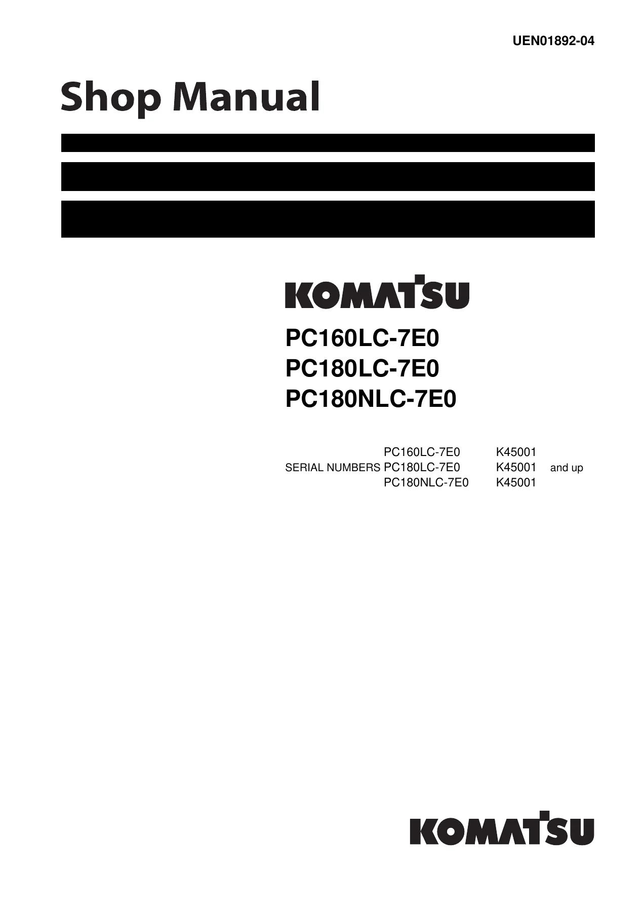
Komatsu PC160LC-7E0 PC180LC-7E0 PC180NLC-7E0 Excavator Shop Manual - PDF Download β€” PDF page 1 preview
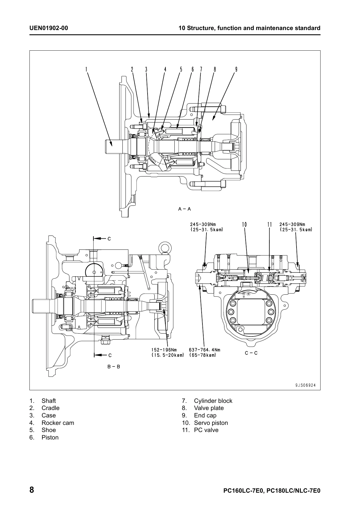
Komatsu PC160LC-7E0 PC180LC-7E0 PC180NLC-7E0 Excavator Shop Manual - PDF Download β€” PDF page 100 preview
Komatsu PC160LC-7E0 PC180LC-7E0 PC180NLC-7E0 Excavator Shop Manual - PDF Download β€” PDF page 144 preview

Instant PDF Delivery

This Komatsu PC160LC-7E0 PC180LC-7E0 PC180NLC-7E0 Excavator Shop Manual is delivered as an instant PDF download after purchase. There is no shipping, no waiting, and no physical media to handle. The PDF works on any device β€” desktop, laptop, tablet, or smartphone β€” and you can print whichever pages you need for the workshop. Keep the complete 958-page Komatsu shop manual on your computer or in the cloud and access it whenever you need it. Get the manual now and have the full service documentation for your PC160LC-7E0, PC180LC-7E0, or PC180NLC-7E0 excavator at your fingertips.
Reviews

There are no reviews yet.

Be the first to review “Komatsu PC160LC-7E0 PC180LC-7E0 PC180NLC-7E0 Excavator Shop Manual – PDF Download”

What Our Customers Say

β˜…β˜…β˜…β˜…β˜… Live reviews from customers
Loading customer reviews...
0
    0
    Your Cart
    Your cart is emptyReturn to Shop
    πŸ›’
    Recently Purchased
    πŸ•’ verified order