
Komatsu PC200-7 PC200LC-7 PC220-7 PC220LC-7 Excavator Shop Manual – Testing & Adjusting Troubleshooting PDF
Original price was: $34.95.$19.95Current price is: $19.95.
Komatsu PC200-7, PC200LC-7, PC220-7 and PC220LC-7 excavator shop manual covering testing, adjusting, troubleshooting, standard value tables, E-mode and H-mode diagnostics, monitor panel functions, wiring and hydraulic circuit diagrams. Instant PDF download.
Description
Komatsu PC200-7 / PC220-7 Excavator Shop Manual – Testing, Adjusting & Troubleshooting
This Komatsu PC200-7, PC200LC-7, PC220-7 and PC220LC-7 excavator shop manual is the testing, adjusting and troubleshooting reference used by service technicians working on the SAA6D102E-2 powered Dash-7 machines. It brings together the standard value tables, measurement procedures, pressure checks, monitor panel special functions and the full E-mode and H-mode troubleshooting flowcharts into one PDF that a working tech can follow directly at the machine.
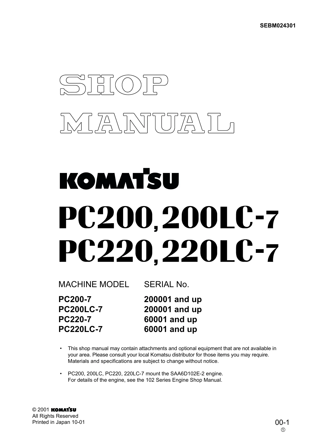
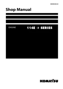
The manual covers the PC200-7 and PC200LC-7 from serial 200001 up, and the PC220-7 and PC220LC-7 from serial 60001 up. Engine detail for the SAA6D102E-2 is referenced to the separate 102 Series Engine Shop Manual, and that note is printed on the first page of this document.
File Details
- Manual type: Komatsu Shop Manual – Testing, Adjusting and Troubleshooting section
- Brand: Komatsu
- Models covered: PC200-7, PC200LC-7, PC220-7, PC220LC-7
- Engine reference: SAA6D102E-2 (full engine detail covered in the 102 Series Engine Shop Manual)
- Serial ranges: PC200-7 and PC200LC-7 – 200001 and up; PC220-7 and PC220LC-7 – 60001 and up
- Language: English
- File format: PDF
- Page count: 330 pages
- Revision note printed on the cover: Disassembly and Assembly chapter scheduled for issue 12-15-2001
Chapters and Sections Covered
- 01 GENERAL
- 10 STRUCTURE, FUNCTION AND MAINTENANCE STANDARD
- 20 TESTING AND ADJUSTING
- Standard Value Table for Engine Related Parts
- Standard Value Table for Chassis Related Parts
- Testing and Adjusting
- Troubleshooting
- Measurement of Exhaust Gas Color
- Adjustment of Valve Clearance
- Measurement of Compression Pressure
- Measurement of Blow-by Pressure
- Inspection and Adjustment of Fuel Injection Timing
- Measurement of Engine Oil Pressure
- Adjustment of Engine Speed Sensor
- Inspection and Adjustment of Air Compressor Belt Tension
- Emergent Escape from Failure in Engine Control System
- Measurement of Clearance in Swing Circle Bearings
- Inspection and Adjustment of Track Shoe Tension
- Inspection and Adjustment of Hydraulic Oil Pressure in the Work Equipment, Swing and Travel Circuit
- Inspection and Adjustment of Control Circuit Oil Pressure
- Inspection and Adjustment of Pump PC Control Circuit Oil Pressure
- Inspection and Adjustment of Pump LS Control Circuit Oil Pressure
- Measurement of Solenoid Valve Output Pressure
- Measurement of PPC Valve Output Pressure
- Adjustment of Work Equipment and Swing PPC Valve
- Inspection of Locations of Hydraulic Drift of Work Equipment
- Release of Remaining Pressure in Hydraulic Circuit
- Measurement of Oil Leakage Amount
- Air Bleeding of Various Parts
- Inspection Procedures for Diode
- Special Function of Multi-Monitor Panel
- Display Method and Special Functions of 7-Segment Monitor Panel
- Preparations for Troubleshooting the Electrical System
- Sequence of Events in Troubleshooting
- Points to Remember When Carrying Out Maintenance
- Checks Before Troubleshooting
- Classification and Steps for Troubleshooting
- Connector Location Chart and Electrical Circuit Diagram by System
- Connection Table for Connector Pin Numbers
- Troubleshooting When Service Code and Failure Code Are Indicated
- Troubleshooting of the Electrical System (E-Mode)
- Troubleshooting of the Hydraulic and Mechanical System (H-Mode)
- 30 DISASSEMBLY AND ASSEMBLY – listed in the contents, to be issued separately per the printed note
- 90 OTHERS
- Hydraulic Circuit Diagram – PC200-7, PC200LC-7
- Hydraulic Circuit Diagram – PC220-7, PC220LC-7
- Electrical Circuit Diagram for Multi-Monitor
- Electrical Circuit Diagram for 7-Segment Monitor
- Electrical Circuit Diagram for Air Conditioner
What This Komatsu PC200-7 / PC220-7 Shop Manual Gives You
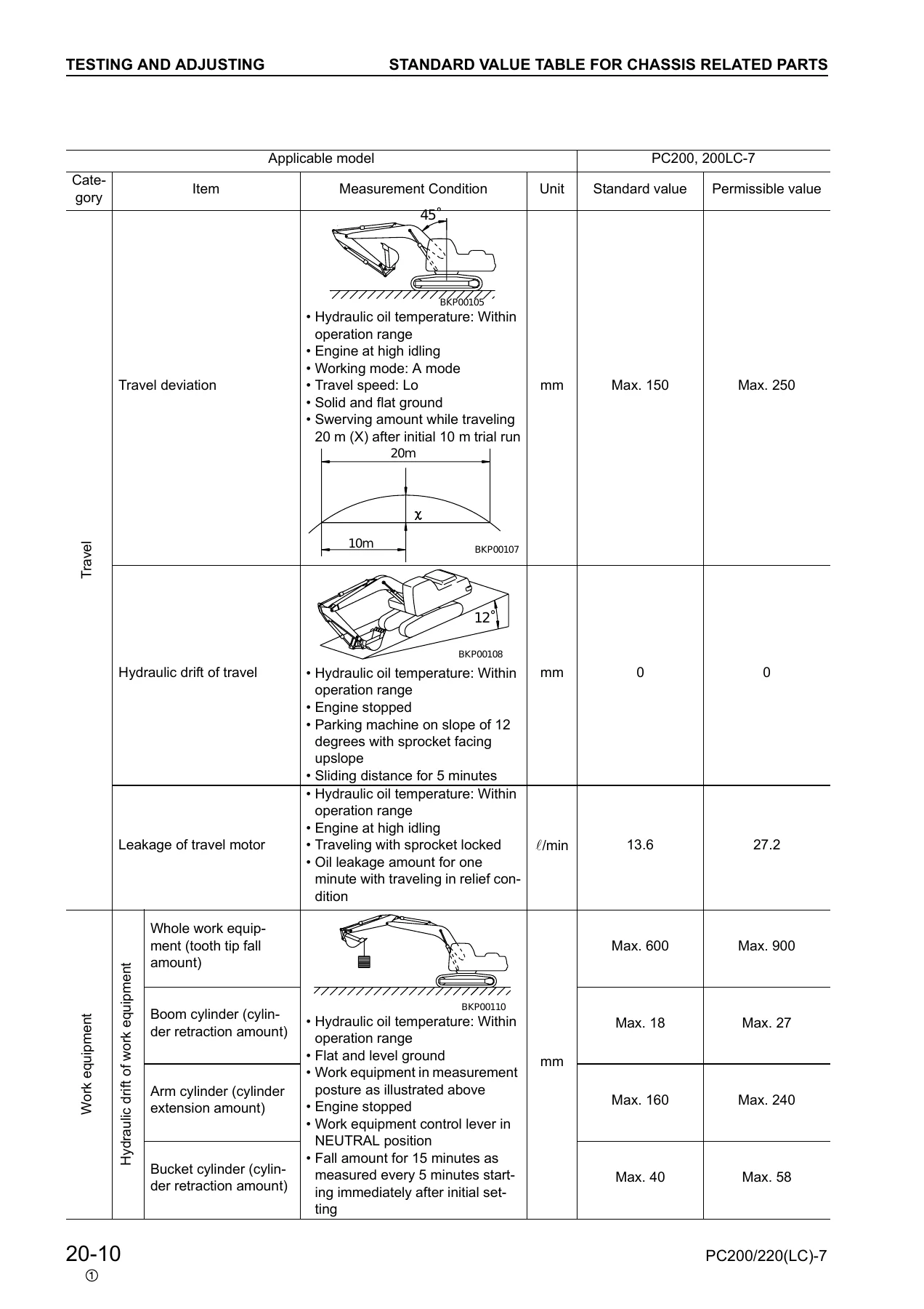
The heart of this document is the testing, adjusting and troubleshooting material. Standard value tables are split into engine-related parts and chassis-related parts, giving new-machine reference values and permissible service limits for engine rpm at low and high idle, fuel pump relief conditions, swing time, hydraulic drift, travel speed Lo and Hi, leakage from the swing and travel motors, travel deviation, boom, arm and bucket cylinder drift amounts and related measurements.
The adjusting section walks through the practical jobs a Dash-7 technician actually performs: setting valve clearance with the crank set at 1.6 TOP, reading compression and blow-by pressure, checking and correcting fuel injection timing with the drive gear timing pin and injection pump timing pin, engine oil pressure measurement, engine speed sensor air-gap setting, air compressor belt tension and the governor spring procedures.
Hydraulically, the manual covers measuring and adjusting work equipment, swing and travel relief pressures, control circuit pressure, the pump PC control circuit, the pump LS control circuit, solenoid valve output pressure, PPC valve output pressure and PPC valve adjustment. Separate procedures cover oil leakage measurement from the boom, arm, bucket, swing motor and travel motor, air bleeding from the pump, cylinders, swing motor and travel motor, and the diode inspection routine for the assembled 8-pin and single 2-pin diodes.
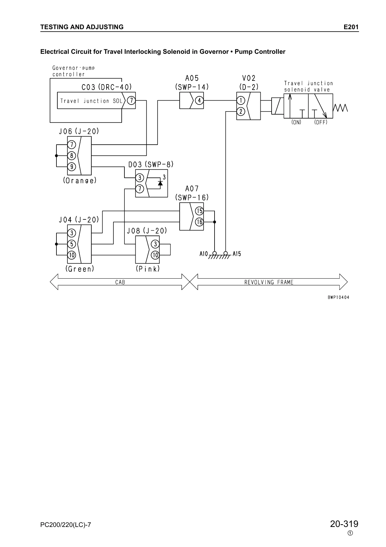
Electrically, this PC200-7 / PC220-7 shop manual goes deep into the governor and pump controller system. Every service code in the electrical system from E101 through E318, plus E501 and E502, has its own troubleshooting table listing failure content, controller response, machine phenomena, the presumed cause and the standard value or resistance/voltage you should see in normal condition. The hydraulic and mechanical H-mode troubleshooting covers H-1 through H-28, from slow work equipment and engine stall through travel, swing and compound-operation faults.
The monitor panel section is unusually complete. Both the multi-monitor Operator’s Menu and Service Menu functions are documented, including the monitoring display codes, bit-pattern tables, the abnormality record and reset procedure, maintenance mode change, phone number entry, default set-up, governor motor adjustment, pump absorption torque adjustment, low idle speed adjustment, service current adjustment, working mode default setting and service meter adjustment. The 7-segment monitor panel is covered separately with its own service code display, monitoring code display and oil maintenance function.
Connector information is provided in two useful forms: a connector table that lists each connector number, type, pin count, device name and grid address for the M, G and P circuits, and a connector pin number connection table showing X type, SWP type, M type, S type, KES 1, HD30 series, DT series, DTM, DTHD, AMP 040, L type, PA, Bendix MS, F type, relay socket and other connector families with their T-adapter part numbers.
Who This Excavator Troubleshooting Manual Suits
- Komatsu field service technicians diagnosing a PC200-7, PC200LC-7, PC220-7 or PC220LC-7 machine on site
- Owners running their own repair and maintenance programs who want the factory standard values and pressure settings
- Independent excavator mechanics who need the electrical troubleshooting flowcharts for the governor and pump controller system
- Fleet workshops maintaining multiple Dash-7 excavators across the PC200 and PC220 families
Put the Dash-7 Testing and Adjusting Data to Work
With the standard value tables in front of you, a pressure gauge reading on the main relief valve or a service code on the monitor panel stops being a mystery. You can compare your actual reading against the Komatsu new-machine value and the permissible limit, identify whether a component is inside spec, and follow the matching troubleshooting chart instead of guessing at parts. The E-mode tables for the governor and pump controller and the H-mode tables for hydraulics and mechanical systems both spell out the presumed causes in order so you can test rather than replace.
Correct procedures and correct values are what separate a repair that lasts from a comeback. The valve clearance and fuel injection timing procedures in this manual require the engine to be set precisely; the relief pressure adjustments specify exactly how many turns of the holder produce how many MPa of change. Using the numbers printed for the PC200-7, PC200LC-7, PC220-7 and PC220LC-7 rather than generic guidance is what keeps the machine performing to its design standard.
IMAGES PREVIEW
The PDF is delivered instantly after payment – no shipping, no waiting on a disc. Open it on a laptop in the workshop, a tablet next to the machine, or a phone in the cab, and print only the pages you need for the job in front of you. Once downloaded, it stays with you as a permanent reference for every PC200-7, PC200LC-7, PC220-7 and PC220LC-7 that comes through your shop.
Reviews
There are no reviews yet.