
Komatsu PC200-7 PC200LC-7 PC220-7 PC220LC-7 Technical Manual – Selected Sections SEBM024312 PDF
Original price was: $50.95.$34.95Current price is: $34.95.
573-page Komatsu technical manual (SEBM024312) for the PC200-7, PC200LC-7, PC220-7 and PC220LC-7 hydraulic excavators. Covers specifications, hydraulic pump and control valve theory, CLSS, swing and travel motors, electronic control, monitor systems, testing and adjusting, and troubleshooting.
Description
Komatsu PC200-7, PC200LC-7, PC220-7 and PC220LC-7 Technical Manual – Selected Sections (SEBM024312)
This technical manual, document number SEBM024312, was published by Komatsu to support the PC200-7, PC200LC-7, PC220-7 and PC220LC-7 hydraulic excavators. The version supplied here is the Selected Sections compilation, which gathers the specification chapter, hydraulic component theory, electronic and monitor control sections, testing and adjusting procedures, and the troubleshooting guides into one continuous document. It is the reference a technician reaches for when a machine needs to be measured, adjusted, diagnosed or repaired rather than simply operated.
File Details
- Manual type: Technical Manual – Selected Sections
- Brand: Komatsu
- Models covered: PC200-7, PC200LC-7, PC220-7, PC220LC-7
- Serial number coverage: PC200-7 200001 and up · PC200LC-7 200001 and up · PC220-7 60001 and up · PC220LC-7 60001 and up
- Language: English
- File format: PDF
- Document number: SEBM024312
- Page count: 573 pages
Chapters Covered
- Specifications
- Weight Table
- Fuel, Coolant, And Lubricants
- Hydraulic Pump
- Control Valve
- CLSS
- Self Pressure Reducing Valve
- Swing Motor
- Reverse Prevention Valve
- Center Swivel Joint
- Travel Motor
- Travel Junction Valve
- Stroke Regulation when Travelling
- Valve Control
- Boom Hydraulic Drift Prevention Valve
- Lift Check Valve
- Attachment Circuit Selector Valve
- Engine Control
- Electronic Control System
- Multi Monitor System
- 7-Segment Monitor System
- Sensor
- Testing and Adjusting
- Troubleshooting
Specifications and Machine Data
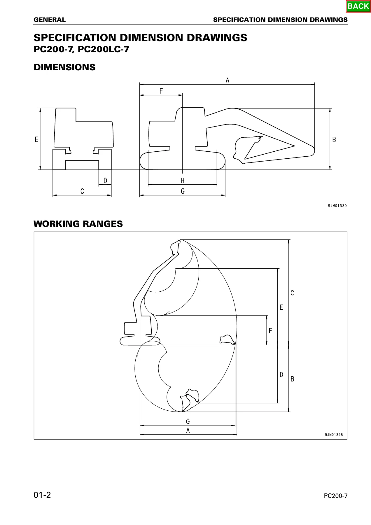
The specification chapter opens with dimension drawings for both the PC200-7/PC200LC-7 and PC220-7/PC220LC-7, then provides full tabulated dimensions, working ranges and machine specifications. Every major figure needed to set up or verify a machine is here: overall length, overall height, overall width, track shoe width, cab height, tail swing radius, track overall length, length of track on ground, minimum ground clearance, maximum digging reach, maximum digging depth, maximum digging height, maximum vertical wall depth, maximum dumping height, minimum dumping height and maximum reach at ground level. Operating weights, bucket capacities, swing speed, travel speed, gradeability and ground pressure are also tabulated for each model. The weight table lists individual component weights – engine assembly, hydraulic pump, radiator, hydraulic tank, fuel tank, revolving frame, cab, counterweight, swing machinery, control valve, travel motor, track frame, track shoe assemblies, boom, arm, bucket and cylinder assemblies – in kilograms for both standard and long undercarriage versions. A fuel, coolant and lubricants table rounds out the chapter with the recommended fluids.
Hydraulic Pump and Control Valve
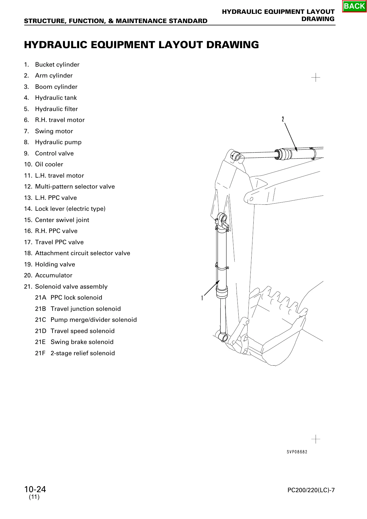
This is the heart of the technical manual. The hydraulic pump section describes the HPV95+95 variable displacement piston pump used on these machines – two pumps in one housing, each rated at 214 L/min with a set pressure of 37.2 MPa (380 kg/cm²). Cutaway illustrations show the shaft, cradle, rocker cam, shoe, piston, cylinder block, valve plate, end cap and servo piston. The LS valve and PC valve are covered in detail: how the LS valve detects load and controls discharge amount based on LS differential pressure ΔPLS, how the PC valve performs equal horsepower control so the pump never absorbs more than the engine can deliver, and how the LS-EPC and PC-EPC solenoids influence those valves electronically. Control valve coverage runs through the 6-spool unit, service valve, pump merge-divider valve, back pressure valve and boom hydraulic drift prevention valve, with individual spool sections for arm, right travel, swing, boom, left travel, bucket and service functions all illustrated and labelled. The CLSS (Closed center Load Sensing System) chapter explains the load-sensing principle, pressure compensation and the flow-divider behaviour that keeps multiple actuators moving in proportion to their spool openings.
Swing, Travel and Auxiliary Valves
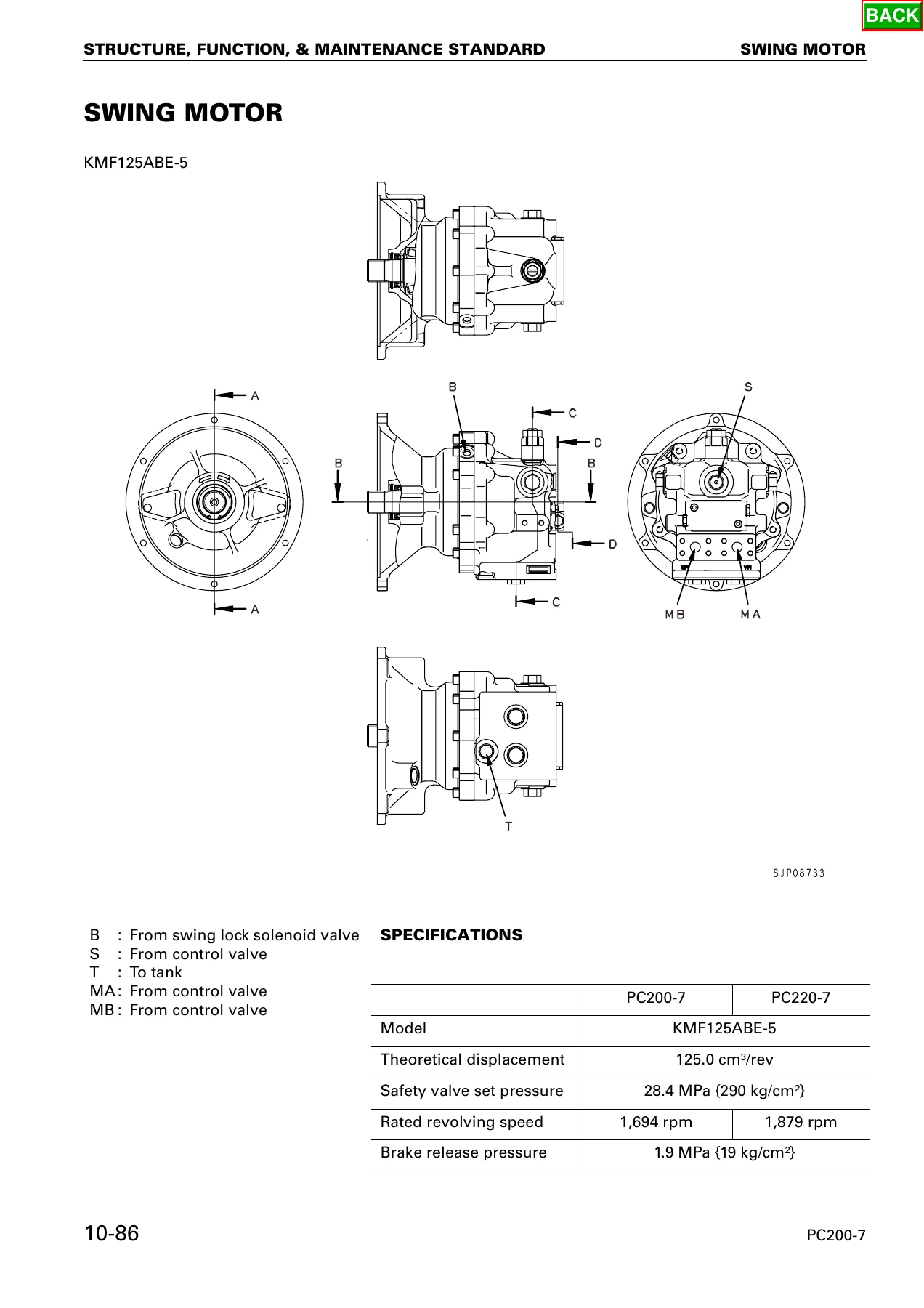
The swing motor section documents the KMF125ABE-5 piston motor, its safety valve set pressure of 28.4 MPa (290 kg/cm²), rated revolving speeds, brake release pressure, and the brake release and application sequence. The reverse prevention valve is explained as the component that reduces swing-back when the upper structure is stopped. Travel is covered through the HMV110-2 piston motor with its two-speed capability, parking brake operation and counterbalance valve function, including the automatic downshift that occurs when travel pressure exceeds 24.5 MPa (250 kg/cm²) and the upshift back to Hi when pressure falls below 14.7 MPa (150 kg/cm²). The travel junction valve, center swivel joint, travel speed solenoid valve and stroke regulation system are all presented with their hydraulic schematics and operating explanations.
Electronic Control System and Monitors
The electronic control portion explains the engine/pump composite control function, pump/valve control, one-touch power maximizing function, auto-deceleration, auto-warm-up and overheat prevention, swing control, travel control and attachment flow control. Work modes (A, E, B and on multi-monitor machines L) are described with the engine torque, engine horsepower and pump discharge curves for each. The monitor chapter covers both the multi-monitor panel and the 7-segment monitor system. For the multi-monitor, the manual details the operator’s menu and service menu, the monitoring function with its code list, the abnormality record, the maintenance record and the adjustment functions. For the 7-segment panel, it covers the service code display, monitoring function, governor adjustment, maintenance period selection, default working mode selection and attachment installation setting. A separate sensor chapter covers the engine revolution sensor, PPC oil pressure switches, pump pressure sensors and the fuel control dial.
Testing and Adjusting
This section reads like a workshop procedure list. It covers inspection and adjustment of engine speed, measurement of exhaust gas color, valve clearance adjustment, compression pressure measurement, blow-by pressure measurement, fuel injection timing, engine oil pressure, engine speed sensor adjustment, air compressor belt tension, swing circle bearing clearance, track shoe tension, hydraulic oil pressure in the work equipment/swing/travel circuits, control circuit oil pressure, pump PC control circuit pressure, pump LS control circuit pressure, solenoid valve output pressures, PPC valve output pressures, and the locations of hydraulic drift. Each procedure gives the measurement conditions, standard values and permissible values so the technician can judge whether a component is within specification.
Troubleshooting
The troubleshooting chapter is split into Service Code (electrical system) and Failure Code (mechanical system) diagnostics, with additional E-mode, H-mode and S-mode procedures for problems that do not produce a code. The manual provides connector location charts, circuit diagrams by system, a connection table for connector pin numbers, and the troubleshooting tables themselves. Common symptoms like the engine not starting, the engine stopping during operation, travel speed not shifting, the machine not swinging, and various work equipment performance issues are each broken down into probable causes with the corresponding check procedures.
What This Manual Lets You Do
The PC200-7, PC200LC-7, PC220-7 and PC220LC-7 are 19 to 24 tonne class hydraulic excavators, and the systems on them are not the sort you can diagnose by ear. The difference between a machine that runs well and one that is quietly wearing itself out is usually a measurement – a relief pressure, a differential pressure, a current draw, a sensor voltage. This manual gives you those numbers. It gives you the hydraulic schematics that show which port to tee into, the electronic control tables that tell you what the controller is expecting, and the monitor functions that let you watch the machine’s own sensors while it is running.
For a workshop, this is the difference between replacing parts and finding the failed component. For an owner-operator, it is the difference between calling a dealer for every hiccup and knowing which of the routine checks you can do yourself. For anyone buying a used machine, the specification and testing sections give a ready-made checklist for assessing the condition of the hydraulic system before money changes hands.
IMAGES PREVIEW
The manual is delivered as an instant PDF download. No shipping, no waiting for a disc. Open it on a laptop, a tablet or a phone, zoom in on a hydraulic schematic, print the troubleshooting flow you need and take it out to the machine.
Reviews
There are no reviews yet.