
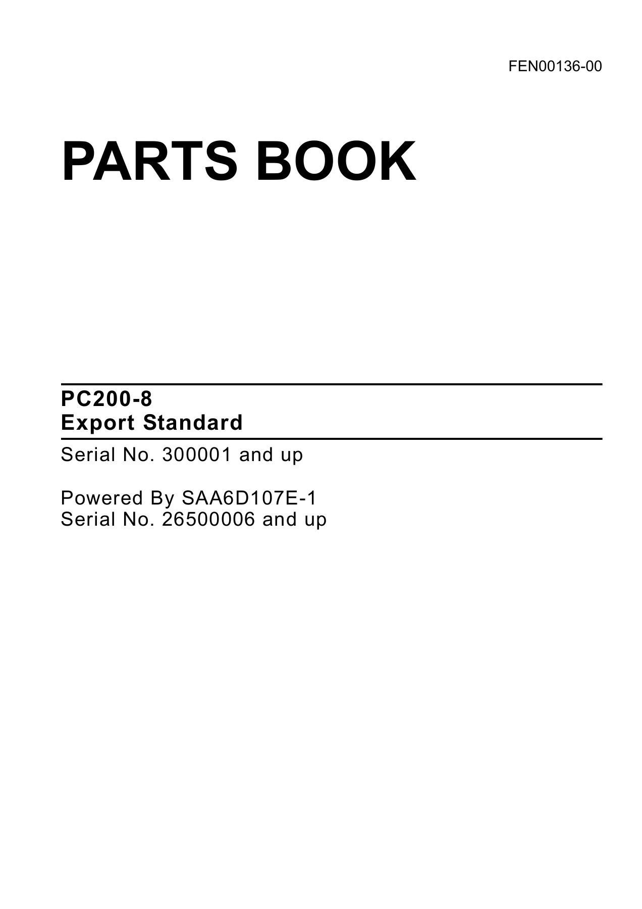
Komatsu PC200-8 Export Standard Parts Book FEN00136-00 – PDF Parts Catalog
Original price was: $49.95.$34.95Current price is: $34.95.
Complete Komatsu PC200-8 Export Standard Parts Book (FEN00136-00). 588-page PDF with exploded views, part numbers, descriptions, quantities and serial ranges for machines 300001 and up and SAA6D107E-1 engines 26500006 and up.
Description
Komatsu PC200-8 Export Standard Parts Book — FEN00136-00
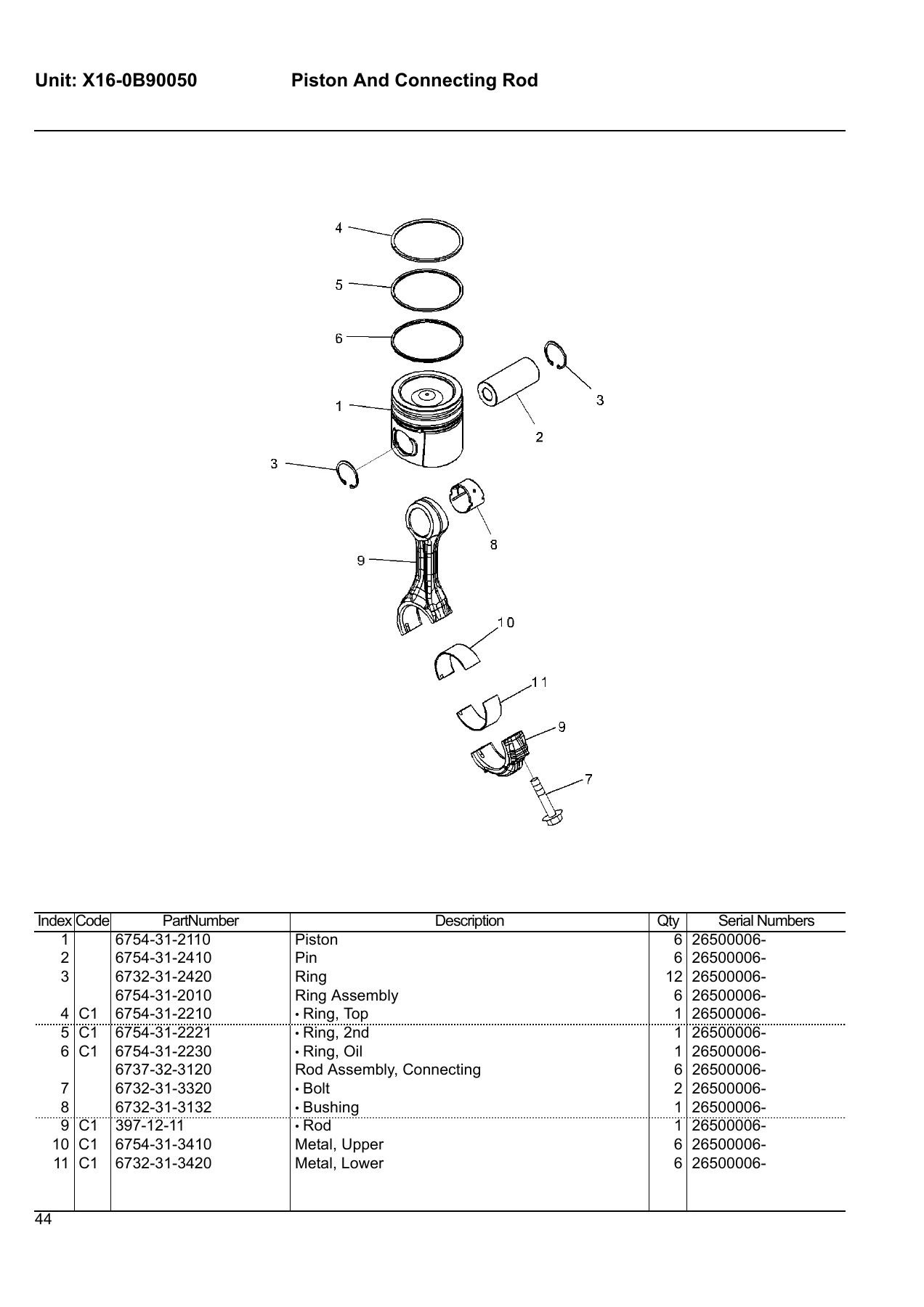
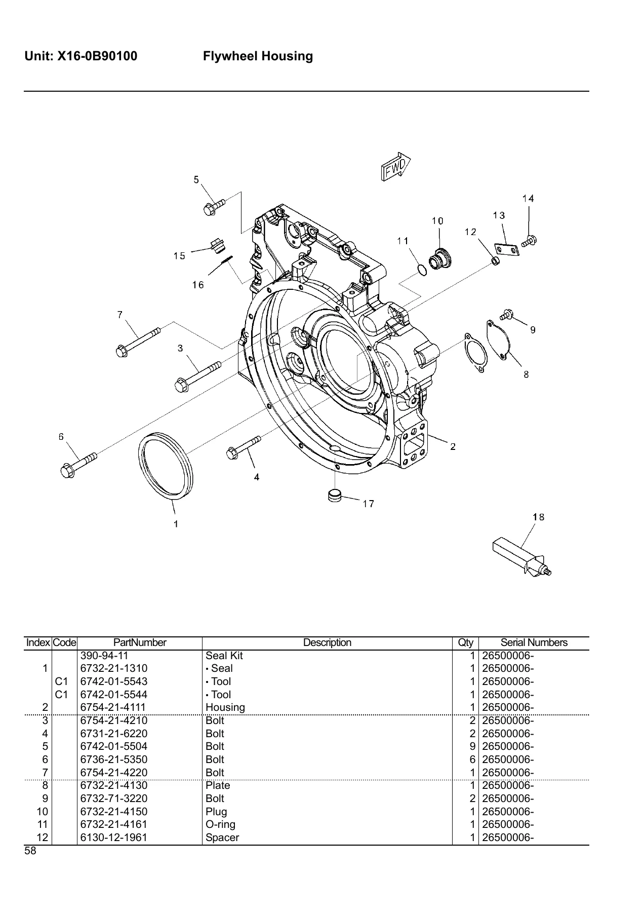
This is the complete Komatsu PC200-8 Export Standard Parts Book, document number FEN00136-00, published September 2005. It covers PC200-8 machines from serial number 300001 and up, powered by the SAA6D107E-1 engine from serial number 26500006 and up. Every exploded illustration is keyed to a parts list that gives the part number, part name, quantity, and applicable serial range — the same lookup layout Komatsu distributors use when you place a parts order.
File Details
- Manual type: Parts Book (Parts Catalog)
- Brand: Komatsu
- Model: PC200-8 Export Standard
- Engine: SAA6D107E-1
- Machine serial number: 300001 and up
- Engine serial number: 26500006 and up
- Document number: FEN00136-00
- Publication date: September 2005
- Languages: English (main parts lists); French, Italian, German, Portuguese, Chinese, Russian and Arabic (front-matter foreword)
- Page count: 588
- File format: PDF
Chapters Covered
- Engine Cylinder Head and Related Parts (SAA6D107E-1)
- Engine Cylinder Block and Related Parts (SAA6D107E-1)
- Engine Valve Mechanism (SAA6D107E-1)
- Engine Front Gear Case and Drive Train (SAA6D107E-1)
- Engine Flywheel Housing and Flywheel (SAA6D107E-1)
- Engine Lubricating System (SAA6D107E-1)
- Engine Fuel System (SAA6D107E-1)
- Engine Cooling System (SAA6D107E-1)
- Engine Electrical System (SAA6D107E-1)
- Engine Accessories and Others (SAA6D107E-1)
- Engine Related Parts
- Cooling System
- Fuel System
- Electrical System
- Hydraulic System
- Frame and Related Parts
- Operator’s Compartment and Control System
- Guards and Covers
- Swing Circle and Related Parts
- Travel System and Related Parts
- Undercarriage
- Work Equipment
- Auxiliary Parts and Tool
- Marks and Plates
- Field Repair Service Parts
- Service Kit Parts
- Numerical Index
Engine — Cylinder Head, Block, Valve Train and Rotating Assembly
The engine section is broken into illustration-driven unit groups that follow the SAA6D107E-1 from top to bottom. The Cylinder Head and Related Parts group shows the valve-less head assembly, intake and exhaust inserts, oil filler cap, head cover, gasket, isolators and studs, along with the air intake port cover, air intake connector and air intake heater. The Cylinder Block and Related Parts group covers the block assembly with its plugs, caps and bushings, the crankshaft assembly with gear, collar, upper and lower main metal assemblies, and the piston and connecting rod set with rings, pin, bushings and rod metal. The Valve Mechanism group shows the rocker arm housing, intake and exhaust rocker arms, crosshead, push rod, camshaft assembly with gear and dowel, and tappets. The Front Gear Case and Drive Train group illustrates the front gear train cover, while the Flywheel Housing and Flywheel unit covers the flywheel housing, seal kit, flywheel mounts and power takeoff. Each exploded view carries index numbers that match the parts list on the following page.
Engine — Lubrication, Fuel, Cooling and Electrical
The Engine Lubricating System unit shows the oil pan, oil pump assembly, oil pan drain, oil filter head and cartridge, oil cooler cover, core and gaskets, oil level gauge and oil level sensor. The Engine Fuel System unit covers the fuel injection pump assembly with pump kit, pump gear, studs and nuts, the fuel injection controller sensors, the fuel injector assembly with clamp and O-rings, the fuel manifold, rail assembly with valve and sensor, and the high-pressure fuel lines and connectors. The Engine Cooling System unit illustrates the cooling fan drive pulley with support assembly, bearings and pulley, the cooling fan, fan spacer, fan belt, belt tensioner, water pump kit, thermostat assembly, coolant connector and coolant inlet connector. The Engine Electrical System unit covers the alternator mounts, the alternator assembly with rotor, stator, frames, bearings and brush holders, the starting motor mounts and starting motor with yoke, armature, plunger, pinion, clutch rollers and brush assembly, plus engine-side electric wiring braces and clips.
Engine — Accessories, Mounts and Related Parts
The Engine Accessories and Others unit shows the front and rear engine lifting eyes and the name and caution plates. The Engine Related Parts unit covers the engine mounts with brackets, cushions, plates, washers and dowel pins, the air cleaner connecting parts including the air cleaner assembly with cover, outer and inner elements and O-ring, the air cleaner frame and hose, and the dumper assembly with hose, elbows and clips.
Machine Cooling, Fuel and Electrical Systems
The machine-level Cooling System covers the radiator assembly with core, sheets, cap, plug, hose, clip, cushion and collars, the aftercooler and oil cooler assemblies, the condenser assembly, and the radiator mount brackets and seals. The Fuel System unit shows the fuel tank with drain valve, elbow, cap, sensor, strainer assembly and float, plus the fuel supply piping with hoses, tubes, clips, grommets and the pre-fuel filter assembly with head, cartridge, bowl, valve and sensor. The Electrical System unit covers the battery, battery cables, terminals, ground cable, horn, travel alarm, and the revolving-frame electric wiring runs with their clips, collars, brackets and grommets.
Hydraulic System
This is the largest single group in the book. The hydraulic oil tank unit is shown both in standard form and with the fitting arrangement for machines with a 1-additional actuator circuit. The main piston pump is documented across multiple sub-assemblies — the pump subassembly, front and rear case subassemblies, cylinder block, valve plate, guide retainer, shoe retainer, piston subassembly, cradle, rocker cam, cover assemblies, couplings and the shaft and bearing sets. The Main Control Valve unit is documented in both the standard 20-page breakdown and a 24-page breakdown for machines with a 1-additional actuator circuit, covering valve body subassembly, spools, seats, springs, retainers, plugs, O-rings, relief valves, suction valves, check valves, unloader valves and the pilot valves. Downstream circuits covered include the suction circuit, delivery circuit, delivery circuit with in-line filter, oil cooler circuit, return circuit (both standard and 1-additional-actuator variants), drain circuit, boom circuit, arm and bucket circuit, additional actuator circuit, travel circuit, swing circuit, OLSS circuit, solenoid valve circuit, pressure switch block, and the Proportional Pressure Control (PPC) valve circuit in both standard and arm-crane-spec form.
Frame, Operator’s Compartment and Control System
The Revolving Frame unit shows the frame casting with its covers, sheets, gaskets, grommets, plugs and brackets, plus the boom foot pin hardware with spacers and plates. The Operator’s Compartment and Control System unit covers the rigid-type and suspension-type operator’s seats, seat belts in 50 mm and 78 mm widths, the air conditioner unit with compressor, brackets, hoses, clips and V-belt, the floor mat, front guard, windshield washer, floor mounts and cushions. The cab section is a large 50-page breakdown covering cab, glass, seals, door assembly, sash, hinges, locks, handles, wiper assembly, antenna, monitor, controller, relays, diodes, radio, ducts, seals, and the pilot valve assemblies for travel and work equipment.
Guards, Covers and Swing Circle
The Guards and Covers unit covers the machine cab frame, hood, LHS and RHS side covers with their frames, hinged covers, locks and sheets, the machine cab partition and cab cover, the battery case with cover, hinge and rod, handrail, counterweight with its sheets and cap, counterweight mounts and under covers. The Swing Circle and Related Parts unit shows the swing circle assembly with seals, nipples, bolts, washers, dowel pins, tube and elbow, plus the swing machinery in five sub-sections — motor assembly, motor subassembly with case, housing, bushings, check valve, spring, plug, drive shaft, bearings, cylinder block, valve plate, center shaft and brake piston, the valve assembly, and the reduction gear train with case, bearings, shaft, seals, gears, carriers, pins and washers. The swivel joint is documented in three sub-sections with rotor, seals, O-rings, cover, shaft, dust seal, ring, snap rings, elbows and flange sets.
Travel System and Undercarriage
The Travel Circuit unit shows the hoses, unions, nipples, O-rings, grommets, bands and covers. The Travel Motor and Final Drive unit is a three-part breakdown covering the motor assembly with case, plugs, end cover, spools, relief valves, springs, rings, bolts, drive shaft, bearings, spacer kit, cylinder block, valve plate, retainer guide, shoe retainer, piston subassembly, rocker cam, brake piston and plates, plus the final drive with seal assembly, hub, bearings, lock nut, lock, carrier, gears, thrust washers, pins, sprocket and mounting bolts. The Undercarriage unit covers the track frame and track frame with full-length track roller guard, track guard, track roller guard, track frame under cover, front idler in two variants, track roller, carrier roller, and six track shoe assembly options — holed triple grouser in 500 mm, 600 mm, 700 mm and 800 mm widths, circular arc shoes, flat shoes, city pad and road liner — each listing links, seals, bushings, pins, shoes, bolts and nuts.
Work Equipment
The Work Equipment section covers the boom in both the 1-additional-actuator variant and the strengthened variant, with bracket, welded bosses, bushings, dust seals, plugs, pins, spacers and plates. The boom cylinder and arm cylinder are documented in full, including cylinder tube, bushings, dust seals, rod, cylinder head, snap ring, packing, O-rings, back-up rings, piston, piston ring, wear rings, plunger, collar, tube, brackets, bands and bolts. The arm section covers the arm assembly, link assembly, bushings, seals, dust seals, pins, spacers, bolts and nuts. The bucket section is extensive — standard backhoe buckets in 0.45, 0.55, 0.7, 0.9 and 1.0 m³, strengthened backhoe bucket, backhoe bucket with thrust play adjuster, trapezoidal bucket, ditch cleaning bucket, slope finishing bucket, clamshell bucket, ripper bucket, 1-shank ripper and 3-shank ripper — each with teeth, pins, locks, adapters, cutters, plates, bolts, nuts, shims and spacers. The boom cylinder head pin and parts-for-less-arm and parts-for-less-bucket groups round out the section.
Auxiliary Parts, Marks and Plates
The Auxiliary Parts and Tool unit lists the general tool set — tool bag, filter wrench, wrenches, screwdriver, hammer, pinch bar, grease gun assembly with nozzle and grease cartridge, hexagon wrenches, and the socket and handle tool kit. The Marks and Plates unit covers the lubrication chart decal (North America Standard), Komatsu logo decal, service instruction decal for the air cleaner, caution plate for the arm, and caution plate for the battery (North America Standard).
Field Repair Service Parts and Service Kit Parts
The Field Repair Service Parts unit covers the SAA6D107E-1 oversize cam bushings, rear seal kit with wear sleeve and seal, main and thrust metal assemblies in 0.25 mm, 0.50 mm, 0.75 mm and 1.00 mm undersizes, rod metal undersizes, and the 0.50 mm oversize piston. The Service Kit Parts unit lists the shoe bolt and nut kits (C01 to C04), the boom cylinder service kit (C05), arm cylinder service kit (C06) and bucket cylinder service kit (C07) with each O-ring, back-up ring, wear ring, piston ring, packing, seal and dust seal itemised.
Numerical Index
A full numerical index closes the book, mapping every part number printed in the manual back to the page and index number where it appears. If you already have a Komatsu part number in hand, this is the fastest way to jump straight to the correct illustration and confirm the description, quantity and serial applicability.
Why This PC200-8 Parts Book Belongs in Your Workshop
Buying a used excavator is one thing. Keeping it running — and keeping the parts orders correct — is where a real parts book pays for itself. This PC200-8 Export Standard Parts Book FEN00136-00 gives you the exact part numbers for every assembly on the machine, with serial-number gating so you order the right revision for your machine’s build. Every illustration is drawn with indexed callouts that match the parts list on the facing page: you see the assembly, find the index number, look up the part number, confirm the quantity needed per machine or per assembly, and place the order.
That workflow matters for jobs like replacing a hydraulic hose, rebuilding a travel motor, sourcing a new boom cylinder seal kit, matching a track shoe width, or chasing an electrical fault in the cab harness. Instead of guessing at a generic parts number and hoping the fit is right, you work from the factory illustration and the printed serial applicability. Whether you’re servicing the SAA6D107E-1 engine, the main piston pump, the main control valve, the swing machinery, the travel motor, the undercarriage or the operator’s compartment, the parts data is here.
IMAGES PREVIEW
The file is delivered as a PDF — instant download, no shipping, printable on any standard printer and readable on any device that opens a PDF. Keep a copy on the shop laptop or tablet, print the pages you need for the job, and work the parts order directly off the exploded views.
Reviews
There are no reviews yet.