★ TRUSTED BY 321,897+ PROFESSIONALS WORLDWIDE
🏢
Trusted Business
Verified & Licensed
🛡️
Virus Free Files
100% Safe Downloads
🔒
Secure Payment
SSL Protected
Instant Delivery
Available Immediately
Sale!

Komatsu PC2000-8 Hydraulic Excavator Shop Manual SEN01607-08 (Serial 20001 and Up)

Original price was: $42.95.Current price is: $25.95.

Komatsu PC2000-8 shop manual SEN01607-08 for serial numbers 20001 and up covering backhoe and loading shovel chassis service, testing, troubleshooting, disassembly, and circuit diagrams.

Instant PDF Download
Available immediately
💾
Save to Your Device
Download & keep forever
🛡️
Antivirus Scanned
100% virus-free
🌍
Trusted Worldwide
175,000+ customers

Description

Komatsu PC2000-8 Hydraulic Excavator Shop Manual SEN01607-08 (Serial 20001 and Up)

This Komatsu PC2000-8 Hydraulic Excavator Shop Manual SEN01607-08 (Serial 20001 and Up) is the workshop volume used to service the large hydraulic excavator on serial numbers 20001 and up. It is written in English and assembled as form SEN01607-08, with supporting brochures such as SEN01609-08 (index), SEN01610-03 (foreword), and SEN01612-02 (specification and technical data). The copyright page shows © 2008 KOMATSU and Printed in Japan 04-08 (01). The book treats both backhoe specification and loading shovel specification on the same PC2000-8 chassis, so a shop can follow the correct piping, cylinder, and work-equipment path for the machine sitting in the bay.

File Details

  • Manual type: Shop Manual (chassis volume)
  • Brand / model: Komatsu PC2000-8 hydraulic excavator
  • Serial range: 20001 and up
  • Language: English
  • Page count: 1463
  • File format: PDF
  • Document number: SEN01607-08
  • Print date: 04-08 (01), © 2008 KOMATSU

Machine and Powerplant Coverage

The specification section identifies engine model SAA12V140E-3: a 4-cycle, water-cooled, V-type direct-injection diesel with turbocharger and air-cooled aftercooler. Cylinder layout is 12 − 140 × 165 mm, piston displacement 30.48 ℓ {30,480 cc}. Flywheel horsepower is given as 728 kW / 1,800 rpm {976 HP / 1,800 rpm}, maximum torque 4,510 Nm / 1,350 rpm {460 kgm / 1,350 rpm}, high idle 1,980 ± 50 rpm, and low idle 825 ± 25 rpm. Electrical starting and charging hardware is 24 V, 11 kW × 2 starting motors, 24 V, 50 A × 2 alternators, and 12 V, 170 Ah × 4 batteries.

Backhoe specification machine weight is 200,000 kg with a 12.0 m³ bucket. Loading shovel specification machine weight is 195,000 kg with an 11.0 m³ bucket. Travel speed is 2.7 km/h and swing speed is 4.8 rpm on both configurations. Gradeability is 33 deg. on the backhoe listing and 35 deg. on the loading shovel listing. Standard shoe width is 810 mm, track gauge 4,600 mm, length of track on ground 5,780 mm, and minimum ground clearance 825 mm. Ground pressure with the standard shoe is 190 kPa {1.94 kg/cm²} (backhoe) and 186 kPa {1.90 kg/cm²} (loading shovel).

Main pumps are two variable-displacement tandem piston units HPV375 + 375. Fan pump is HPV95 + 95 (shown with SAL / SBL gear-type PTO lubrication pump in the circuit). Published deliveries are main pump P1 629 + 629 ℓ/min, P2 518 + 518 ℓ/min, fan pump 160 + 160 ℓ/min, and PTO lubrication pump 35 ℓ/min. Set pressures are main pump 29.6 MPa {300 kg/cm²} and fan pump 24.5 MPa {250 kg/cm²}. Control valves are 5-spool + 5-spool type × 2. Travel motors are KMF340 piston motors with brake valve and shaft brake (two units). Swing motors are KMF230 piston motors with safety valve and shaft brake (two units). Fluid capacities in the lubricant table include engine oil pan 128 ℓ specified / 120 ℓ refill, PTO case 36 ℓ, swing machinery 30 ℓ each front and rear, final drive 85 ℓ each side, hydraulic system 2,400 ℓ specified / 1,300 ℓ refill, fuel tank 3,400 ℓ, cooling system 180 ℓ, and grease 200 ℓ.

How-to-read notes in the foreword state that shop manuals are divided into a chassis volume and an engine volume, and that the engine unit itself is covered in the engine volume for the mounted engine model. This SEN01607-08 file is the chassis shop manual: it still includes engine-related testing, injector and seal R&I, fuel-system work, S-mode engine troubleshooting charts, and controller procedures that a machine shop actually performs on the excavator, but it is not a substitute for a separate engine-only rebuild volume if one is required for deep internal engine overhaul.

Chapters Covered

  • 00 Index and foreword — composition of shop manual, table of contents, safety notice, how to read the shop manual, maintenance-standard terms, electric and hydraulic component handling, engine connectors, electric wire code, operation precautions, push-pull coupler method, standard tightening torque table, conversion table
  • 01 Specification — specification drawings, specifications, weight table, table of fuel, coolant and lubricants
  • 10 Structure, function and maintenance standard — engine and cooling system (radiator and oil cooler, PTO, PTO lubrication); power train (swing machinery, swing circle, final drive, sprocket); undercarriage and frame (track frame, idler, carrier roller, track roller, track shoe, HIC system)
  • Hydraulic system, Part 1 — piping drawings, hydraulic tank, oil cooler, line / pilot / return / motor-drain / pump-drain filters, accumulator, travel junction valve, solenoid valve, hydraulic cylinder, greasing system, center swivel joint, hydraulic ladder
  • Hydraulic system, Part 2 — control valve, electronic OLSS system, swing motor, cooling fan motor, cooling fan pump
  • Hydraulic system, Part 3 — travel motor, hydraulic pump, PPC valve, variable back pressure valve, suction selector valve, PPC cut-off valve
  • Work equipment — dimensions for backhoe and loading shovel arrangements
  • Cab and its attachments — air conditioner piping, cab
  • Electrical system — engine control, electrical control system, monitor system, sensors, ORBCOMM terminal
  • 20 Standard value table — testing/adjusting/troubleshooting values plus chassis tables for backhoe specification and loading shovel specification
  • 30 Testing and adjusting, Parts 1–4 — engine measurements (speed, boost, exhaust temperature and color, valve clearance, compression, blow-by, oil and fuel pressure, air bleed, belt tension); HIC and track tension; circuit pressures, fan speed and EPC current, PPC and solenoid outlet pressures, travel deviation, hydraulic drift and leakage, residual-pressure relief, air bleeding, auto-grease and hydraulic ladder adjustments; machine-monitor special functions; VHMS initial setting and Pm-clinic measurement
  • 40 Troubleshooting — failure code table and fuse locations; general troubleshooting information; troubleshooting by failure code Parts 1–7; electrical system E-mode; hydraulic and mechanical H-mode; mechanical / engine S-mode
  • 50 Disassembly and assembly — general information, special tools, coating materials; power container, engine/PTO/pump, radiator, aftercooler, oil cooler, fuel cooler, cooling assembly, fan motor, fuel tank; fuel supply pump, cylinder head, fuel injector, front and rear engine oil seals; PTO, swing machinery, swing circle, final drive; undercarriage components, revolving frame, counterweight, hydraulic ladder; hydraulic tank, pumps, control valve, center swivel joint, swing and travel motors, PPC valves, hydraulic cylinders; boom, arm, bucket and bottom-dump work equipment; cab glass and cab base; air conditioner, monitor, engine / pump / VHMS controllers, Orbcomm terminal
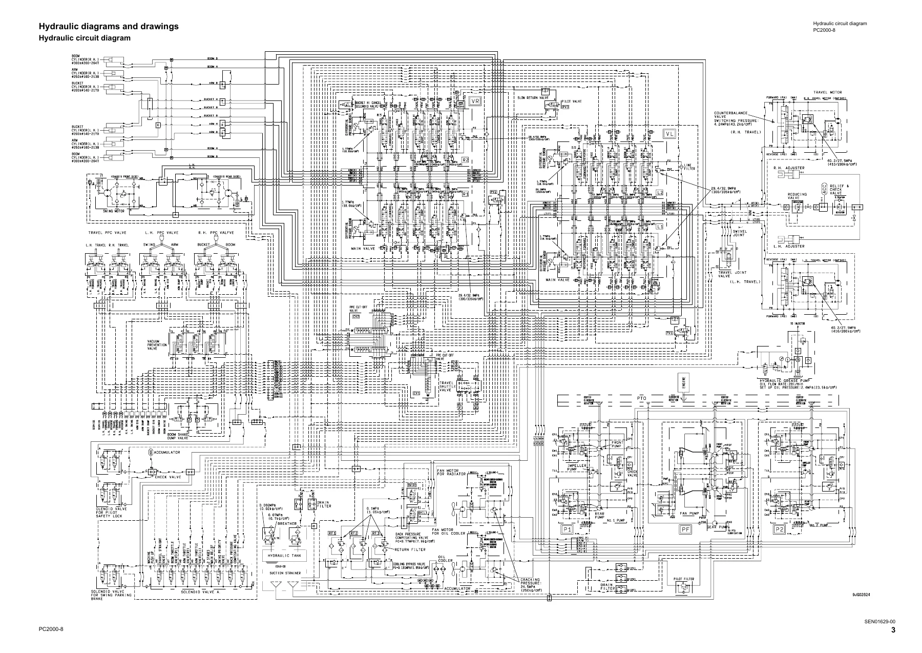
  • 90 Diagrams and drawings — hydraulic circuit diagram; electrical circuit diagrams 1/12 through 12/12; connector arrangement diagram

Complete PDF Bookmark Tree

Complete Bookmarks

The complete bookmarks in the “Komatsu PC2000-8 Hydraulic Excavator Shop Manual SEN01607-08 (Serial 20001 and Up)” are as follows:

COVERp. 1
00 Index and foreword
Indexp. 3
Composition of shop manualp. 4
Table of contentsp. 6
Foreword and general informationp. 19
Safety noticep. 20
How to read the shop manualp. 25
Explanation of terms for maintenance standardp. 27
Handling of electric equipment and hydraulic componentp. 29
Handling of connectors newly used for enginesp. 38
How to read electric wire codep. 41
Precautions when carrying out operationp. 44
Method of disassembling and connecting push-pull type couplerp. 47
Standard tightening torque tablep. 50
Conversion tablep. 54
01 Specification
Specification and technical datap. 61
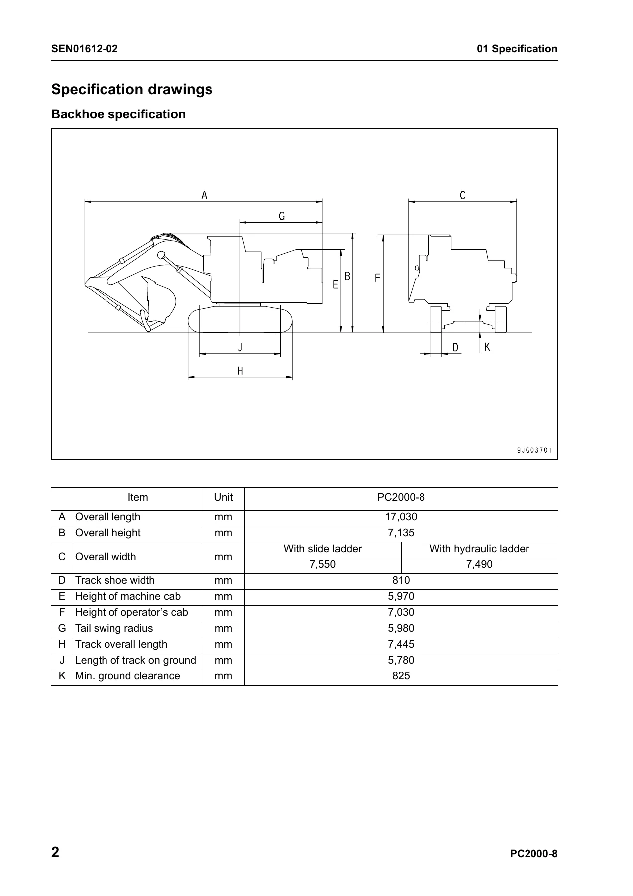
Specification drawingsp. 62
Specificationsp. 66
Weight tablep. 70
Table of fuel, coolant and lubricantsp. 76
10 Structure, function and maintenance standard
Engine and cooling systemp. 79
Engine and cooling systemp. 80
Radiator and oil coolerp. 80
PTOp. 82
PTO lubrication systemp. 84
Power trainp. 86
Power trainp. 87
Power trainp. 87
Swing machineryp. 89
Swing circlep. 91
Final drivep. 92
Sprocketp. 94
Undercarriage and framep. 97
Undercarriage and framep. 98
Track framep. 98
Idlerp. 100
Carrier rollerp. 102
Track rollerp. 103
Track shoep. 104
HIC systemp. 109
Hydraulic system, Part 1p. 112
Hydraulic piping drawingp. 115
Hydraulic tankp. 119
Oil coolerp. 121
Line oil filterp. 123
Pilot oil filterp. 124
Return oil filterp. 125
Motor drain oil filterp. 126
Pump drain filterp. 127
Accumulatorp. 128
Travel junction valvep. 130
Solenoid valvep. 133
Hydraulic cylinderp. 141
Greasing systemp. 145
Center swivel jointp. 155
Hydraulic ladder systemp. 156
Hydraulic system, Part 2p. 162
Hydraulic system, Part 2p. 163
Control valvep. 163
Electronic OLSS systemp. 191
Swing motorp. 195
Cooling fan motor (For radiator and oil cooler)p. 203
Cooling fan pumpp. 209
Hydraulic system, Part 3p. 224
Hydraulic system, Part 3p. 225
Travel motorp. 225
Hydraulic pumpp. 237
PPC valvep. 255
Variable back pressure valvep. 267
Suction selector valvep. 271
PPC cut-off valvep. 275
Work equipmentp. 284
Work equipmentp. 285
Dimensions of work equipmentp. 289
Cab and its attachmentsp. 294
Cab and its attachmentsp. 295
Air conditioner pipingp. 295
Cabp. 296
Electrical systemp. 300
Electrical systemp. 301
Engine controlp. 301
Electrical control systemp. 312
Monitor systemp. 354
Sensorp. 382
ORBCOMM terminalp. 394
20 Standard value table
Standard service value tablep. 396
Standard service value tablep. 397
Standard service value table for testing, adjusting, and troubleshootingp. 397
Standard service value table for chassis (Backhoe specification)p. 398
Standard service value table for chassis (Loading shovel specification)p. 409
30 Testing and adjusting
Testing and adjusting, Part 1p. 422
Testing and adjusting, Part 1p. 424
Tools for testing, adjusting, and troubleshootingp. 424
Measuring engine speedp. 427
Testing air boost pressurep. 428
Testing exhaust temperaturep. 429
Testing exhaust colorp. 430
Adjusting valve clearancep. 432
Testing compression pressurep. 434
Testing blow-by pressurep. 436
Testing engine oil pressurep. 437
Handling fuel system partsp. 438
Releasing residual pressure in fuel systemp. 438
Testing fuel pressurep. 439
Testing leakage from pressure limiter and return rate from injectorp. 440
Bleeding air from fuel circuitp. 443
Bleeding air from fuel circuit (lowgrade fuel specification)p. 447
Testing fuel system for leakagep. 449
Testing and adjusting air conditioner compressor belt tensionp. 451
Testing and adjusting, Part 2p. 454
Testing and adjusting, Part 2p. 456
Testing swing circle bearing clearancep. 456
Remaining pressure relief from HIC circuitp. 457
Gas filling in HIC circuit accumulatorp. 458
Bleeding air from HIC circuit and supplying oil to itp. 459
Testing and adjusting track shoe tensionp. 461
Testing and adjusting work equipment, swing and travel circuit oil pressuresp. 464
Testing and adjusting control circuit oil pressure (output pressure of self pressure reducing valve)p. 468
Testing and adjusting main pump control signalp. 470
Measuring fan speedp. 473
Measuring fan pump EPC solenoid currentp. 474
Measuring fan pump EPC solenoid valve output pressurep. 475
Oil pressure measuring points for pump discharge pressure or jet sensor differential pressurep. 477
Measuring PPC valve output pressurep. 478
Measuring solenoid valve outlet pressurep. 483
Adjusting work equipment and swing PPC valvep. 485
Testing and adjusting travel deviationp. 486
Testing work equipment hydraulic drift cause portionp. 488
Testing oil leakagep. 489
Remaining pressure relief from hydraulic circuitp. 492
Air bleeding from each componentp. 493
Air bleeding from PPC circuitp. 498
Testing and adjusting auto grease systemp. 500
Adjusting mirrorsp. 503
Testing and adjusting clearance of hydraulic ladder proximity switchp. 505
Testing and adjusting position of hydraulic ladder position sensor platep. 507
Testing and adjusting, Part 3p. 510
Testing and adjusting, Part 3p. 511
Special functions of machine monitorp. 511
Handling controller voltage circuitp. 566
Testing and adjusting, Part 4p. 568
Testing and adjusting, Part 4p. 569
VHMS controller initial setting procedurep. 569
Precautions for replacing VHMS controllerp. 586
Preparation work for troubleshooting of electrical systemp. 592
Pm-clinic servicep. 594
Measurement procedurep. 595
40 Troubleshooting
Failure code table and fuse locationsp. 610
Failure code table and fuse locationsp. 611
Failure code tablep. 611
Before carrying out troubleshooting of electrical systemp. 618
General information on troubleshootingp. 624
General information on troubleshootingp. 625
Points to remember when troubleshootingp. 625
Sequence of events in troubleshootingp. 626
Checks before troubleshootingp. 627
Classification and procedures of troubleshootingp. 628
Connection table for connector pin numbersp. 632
T- branch box and T- branch adapter tablep. 668
Troubleshooting by failure code, Part 1p. 672
Troubleshooting by failure code, Part 1p. 675
Failure code [0410KA] Fuel LV. Sensor Failurep. 675
Failure code [0410KB] Fuel LV. Sensor Failurep. 677
Failure code [6014NX] Hydraulic Oil Filter Clogging (or change of VHMS-LED display from n5 to 51)p. 679
Failure code [8800ZG] Auto grease abnormallyp. 680
Failure code [7@HAZL] VR1/P1F Relief Press Abnormalityp. 681
Failure code [7@HBZL] VL1/P1R Relief Press Abnormalityp. 682
Failure code [7@HCZL] VR2/P2F Relief Press Abnormalityp. 683
Failure code [7@HDZL] VL2/P2R Relief Press Abnormalityp. 685
Failure code [AA10NX] Aircleaner Cloggingp. 687
Failure code [AB00KE] Charge Voltage Lowp. 689
Failure code [aB00KE] Low Upper ALR Charge Voltage (or change of VHMS-LED display from n9 to 11)p. 691
Failure code [B@BAZG] Eng. Oil Press. Lowp. 693
Failure code [B@BAZK] Eng. Oil Level Lowp. 695
Failure code [B@BCNS] Eng. Water Overheatp. 697
Failure code [B@BCZK] Eng. Water Lvl Lowp. 699
Failure code [B@CBNS] PTO Oil Overheat (or change of VHMS-LED display from n5 to 61)p. 701
Failure code [B@HANS] Hydr. Oil Overheatp. 703
Failure code [B@HAZK] Low Hydraulic Oil Level (or change of VHMSLED display from n5 to 52)p. 705
Failure code [CA111] ECM Critical Internal Failurep. 707
Failure code [CB111] ECM Critical Internal Failurep. 709
Failure code [CA115] Eng. Ne and Bkup Speed Sens Errorp. 711
Failure code [CB115] Eng. Ne and Bkup Speed Sens Errorp. 712
Failure code [CA122] Chg Air Press Sensor High Errorp. 713
Failure code [CA123] Chg Air Press Sensor Low Errorp. 715
Failure code [CA131] Throttle Sensor High Errorp. 717
Failure code [CA132] Throttle Sensor Low Errorp. 719
Failure code [CA135] Eng Oil Press Sensor High Errorp. 721
Failure code [CA141] Eng Oil Press Sensor Low Errorp. 723
Failure code [CA144] Coolant Temp Sens High Errorp. 725
Failure code [CA145] Coolant Temp Sens Low Errorp. 727
Failure code [CA153] Chg Air Temp Sensor High Errorp. 729
Failure code [CA154] Chg Air Temp Sensor Low Errorp. 731
Failure code [CA187] Sens Supply 2 Volt Low Errorp. 733
Failure code [CB187] Sens Supply 2 Volt Low Errorp. 733
Failure code [CA212] Eng Oil Temp Sensor High Errorp. 735
Failure code [CA213] Eng Oil Temp Sensor Low Errorp. 737
Troubleshooting by failure code, Part 2p. 740
Troubleshooting by failure code, Part 2p. 742
Failure code [CA221] Ambient Press Sens High Errorp. 742
Failure code [CA222] Ambient Press Sens Low Errorp. 744
Failure code [CA227] Sens Supply 2 Volt High Errorp. 745
Failure code [CB227] Sens Supply 2 Volt High Errorp. 747
Failure code [CA234] Eng Over Speedp. 749
Failure code [CA238] Ne Speed Sens Supply Volt Errorp. 750
Failure code [CB238] Ne Speed Sens Supply Volt Errorp. 752
Failure code [CA263] Fuel Temp Sensor High Errorp. 754
Failure code [CB263] Fuel Temp Sensor High Errorp. 756
Failure code [CA265] Fuel Temp Sensor Low Errorp. 757
Failure code [CB265] Fuel Temp Sensor Low Errorp. 757
Failure code [CA271] IMV/PCV1 Short Errorp. 758
Failure code [CB271] IMV/PCV1 Short Errorp. 760
Failure code [CA272] IMV/PCV1 Open Errorp. 762
Failure code [CB272] IMV/PCV1 Open Errorp. 764
Failure code [CA273] PCV2 Short Errorp. 766
Failure code [CB273] PCV2 Short Errorp. 768
Failure code [CA274] PCV2 Open Errorp. 770
Failure code [CB274] PCV2 Open Errorp. 772
Failure code [CA322] Inj #1(L#1) Open/Short Errorp. 773
Failure code [CA323] Inj #5(L#5) Open/Short Errorp. 775
Failure code [CA324] Inj #3(L#3) Open/Short Errorp. 777
Failure code [CA325] Inj #6(L#6) Open/Short Errorp. 779
Failure code [CA331] Inj #2(L#2) Open/Short Errorp. 781
Failure code [CA332] Inj #4(L#4) Open/Short Errorp. 783
Failure code [CA342] Calibration Code Incompatibilityp. 785
Failure code [CB342] Calibration Code Incompatibilityp. 785
Failure code [CA351] Injectors Drive Circuit Errorp. 786
Failure code [CB351] Injectors Drive Circuit Errorp. 788
Failure code [CA352] Sens Supply 1 Volt Low Errorp. 790
Failure code [CB352] Sens Supply 1 Volt Low Errorp. 790
Failure code [CA386] Sens Supply 1 Volt High Errorp. 791
Failure code [CB386] Sens Supply 1 Volt High Errorp. 793
Failure code [CA441] Battery Voltage Low Errorp. 795
Failure code [CB441] Battery Voltage Low Errorp. 795
Failure code [CA442] Battery Voltage High Errorp. 796
Failure code [CB442] Battery Voltage High Errorp. 796
Failure code [CA449] Rail Press Very High Errorp. 797
Failure code [CB449] Rail Press Very High Errorp. 797
Troubleshooting by failure code, Part 3p. 799
Troubleshooting by failure code, Part 3p. 801
Failure code [CA451] Rail Press Sensor High Errorp. 801
Failure code [CB451] Rail Press Sensor High Errorp. 803
Failure code [CA452] Rail Press Sensor Low Errorp. 805
Failure code [CB452] Rail Press Sensor Low Errorp. 805
Failure code [CA553] Rail Press High Errorp. 806
Failure code [CB553] Rail Press High Errorp. 807
Failure code [CA554] Rail Press Sensor In Range Errorp. 808
Failure code [CB554] Rail Press Sensor In Range Errorp. 808
Failure code [CA559] Rail Press Low Errorp. 809
Failure code [CB559] Rail Press Low Errorp. 813
Failure code [CA689] Eng Ne Speed Sensor Errorp. 817
Failure code [CB689] Eng Ne Speed Sensor Errorp. 819
Failure code [CA691] Intake Air Temp Sens High Errorp. 821
Failure code [CA692] Intake Air Temp Sens Low Errorp. 823
Failure code [CA731] Eng Bkup Speed Sens Phase Errorp. 824
Failure code [CB731] Eng Bkup Speed Sens Phase Errorp. 824
Failure code [CA757] All Persistent Data Lost Errorp. 825
Failure code [CB757] All Persistent Data Lost Errorp. 825
Failure code [CA778] Eng Bkup Speed Sensor Errorp. 826
Failure code [CB778] Eng Bkup Speed Sensor Errorp. 828
Failure code [CA781] CEN Communication Errorp. 830
Failure code [CB781] CEN Communication Errorp. 832
Failure code [CA1117] Persistent Data Lost Errorp. 833
Failure code [CB1117] Persistent Data Lost Errorp. 833
Failure code [CA1257] Harness Key Errorp. 834
Failure code [CB1257] Harness Key Errorp. 835
Failure code [CB1548] Inj #7(R#1) Open/Short Errorp. 836
Failure code [CB1549] Inj #8(R#2) Open/Short Errorp. 838
Failure code [CB1551] Inj #10(R#4) Open/Short Errorp. 840
Failure code [CB1552] Inj #11(R#5) Open/Short Errorp. 842
Failure code [CB1553] Inj #12(R#6) Open/Short Errorp. 844
Failure code [CB1622] Inj #9(R#3) Open/Short Errorp. 846
Failure code [CA1633] KOMNET Data link Time out Errorp. 848
Failure code [CA2185] Throt Sens Sup Volt High Errorp. 850
Failure code [CA2186] Throt Sens Sup Volt Low Errorp. 852
Failure code [CA2249] Rail Press Very Low Errorp. 853
Failure code [CB2249] Rail Press Very Low Errorp. 853
Failure code [CA2555] Grid Heater Relay Volt Low Errorp. 854
Failure code [CA2556] Grid Heater Relay Volt High Errorp. 855
Troubleshooting by failure code, Part 4p. 858
Troubleshooting by failure code, Part 4p. 861
Failure code [D110KB] Battery Relay Drive S/Cp. 861
Failure code [D163KB] Flash Light Relay S/Cp. 863
Failure code [D195KA] Step Light Relay Discp. 865
Failure code [D195KY] Step Light Relay S/Cp. 867
Failure code [D1E9KB] Wiper Drive Relay 1 S/Cp. 869
Failure code [D1EAKB] Wiper Drive Relay 2 S/Cp. 871
Failure code [D1EBKB] Lower Wiper Brake Relay Short Circuitp. 873
Failure code [D1ECKB] Upper Wiper Brake Relay Short Circuitp. 875
Failure code [DA22KK] Pump 1 Solenoid Power Low Errorp. 877
Failure code [dA22KK] Pump 2 Solenoid Power Low Errorp. 879
Failure code [DA25KP] Pump 1 Sens Supply Vol Low Errorp. 881
Failure code [dA25KP] Pump 2 Sens Supply Vol Low Errorp. 883
Failure code [DA26KP] 5V Sensor 2 Power Abnormalityp. 885
Failure code [DA29KQ] Pump 1 Model Select Abnormalityp. 887
Failure code [dA29KQ] Pump 2 Model Select Abnormalityp. 889
Failure code [DA2RMC] CAN Discon (Pump 1 Con Detected)p. 891
Failure code [dA2RMC] CAN Discon (Pump 2 Con Detected)p. 893
Failure code [DA2TMC] Pump Comm. ECM Child Abnormalityp. 895
Failure code [DBB0KK] VHMS Source Voltage Error (or change of VHMS-LED display from n9 to 01)p. 897
Failure code [DBB0KQ] VHMS Connector Mismatch (or change of VHMS-LED display from nF to 11)p. 899
Failure code [DBB5KP] VHMS 5V source sys Error (or change of VHMSLED display from n9 to 04)p. 901
Failure code [DBB6KP] VHMS 24V source sys Error (or change of VHMS-LED display from n9 to 02)p. 903
Failure code [DBBQKR] KOM-NET/c error (or change of VHMS-LED display from n8 to 02)p. 905
Failure code [DGE5KX] Ambient Air Temp Sensor Failure (or change of VHMS-LED display from n4 to 01)p. 907
Failure code [DGH2KB] Hydr. Oil Temp. Sensor S/Cp. 909
Failure code [DGT3KZ] PTO Temp Sensor Failure (or change of VHMSLED display from n5 to 01)p. 911
Troubleshooting by failure code, Part 5p. 914
Troubleshooting by failure code, Part 5p. 916
Failure code [DGT5KA] Exhaust Temp. Sensor LBF Failure (or change of VHMS-LED display from n3 to 12)p. 916
Failure code [dGT5KA] Exhaust Temp. Sensor LBR Failure (or change of VHMS-LED display from n3 to 22)p. 918
Failure code [DGT5KB] Exhaust Temp. Sensor LBF Failure (or change of VHMS-LED display from n3 to 11)p. 920
Failure code [dGT5KB] Exhaust Temp. Sensor LBR Failure (or change of VHMS-LED display from n3 to 21)p. 922
Failure code [DGT6KA] Exhaust Temp. Sensor RBF Failure (or change of VHMS-LED display from n3 to 24)p. 924
Failure code [dGT6KA] Exhaust Temp. Sensor RBR Failure (or change of VHMS-LED display from n3 to 26)p. 926
Failure code [DGT6KB] Exhaust Temp. Sensor RBF Failure (or change of VHMS-LED display from n3 to 23)p. 928
Failure code [dGT6KB] Exhaust Temp. Sensor RBR Failure (or change of VHMS-LED display from n3 to 26)p. 930
Failure code [DH25KX] VR1/P1F J/S Dif Press Sensor Abnormalityp. 932
Failure code [DH26KX] VL1/P1R J/S Dif Press Sensor Abnormalityp. 934
Failure code [DH27KX] VR2/P2F J/S Dif Press Sensor Abnormalityp. 936
Failure code [DH28KX] VL2/P2R J/S Dif Press Sensor Abnormalityp. 938
Failure code [DHE5KB] Blowby Pres. Sensor Failure (or change of VHMS-LED display from n3 to 32)p. 940
Failure code [DHE5KY] Blowby Pres. Sensor Failure (or change of VHMS-LED display from n3 to 31)p. 942
Failure code [DHH2KA] Hydraulic oil filter Sensor Failure (or change of VHMS-LED display from n5 to 53)p. 944
Failure code [DHPEKX] VR1/P1F Pump P. Sensor Abnormalityp. 945
Failure code [DHPFKX] VL1/P1R Pump P. Sensor Abnormalityp. 947
Failure code [DHPGKX] VR2/P2F Pump P. Sensor Abnormalityp. 949
Failure code [DHPHKX] VL2/P2R Pump P. Sensor Abnormalityp. 951
Failure code [DHPSKX] Auto Grease Press Sensor Abnormalityp. 953
Failure code [DHPTKX] Fan(RAD) Pump P. Sensor Open Circuitp. 955
Failure code [DHPUKX] Fan(O/C) Pump P. Sensor Open Circuitp. 957
Failure code [DHS3KX] Arm Dig PPC Press Sensor Abnormalityp. 959
Failure code [DHS4KX] Bucket Curl PPC Press Sensor Abnormalityp. 961
Failure code [DHS8KX] Boom Raise PPC Press Sensor Abnormalityp. 963
Failure code [DHS9KX] Boom Lower PPC Press Sensor Abnormalityp. 965
Failure code [DHSAKX] Swing Right PPC Press Sensor Abnormalityp. 967
Failure code [DHSBKX] Swing Left PPC Press Sensor Abnormalityp. 969
Failure code [DHSCKX] Arm Dump PPC Press Sensor Abnormalityp. 971
Failure code [DHSDKX] Bucket Dump PPC Press Sensor Abnormalityp. 973
Troubleshooting by failure code, Part 6p. 976
Troubleshooting by failure code, Part 6p. 978
Failure code [DUM3KB] Auto Grease Caution LED Short Circuitp. 978
Failure code [DUM4KB] FAN Reverse LED Short Circuitp. 979
Failure code [DV20KB] Travel Alarm S/Cp. 980
Failure code [DW41KA] Swing Priority Sol Open Circuitp. 982
Failure code [DW41KB] Swing Priority Sol Short Circuitp. 984
Failure code [DW45KA] Swing Brake Sol. Disc.p. 986
Failure code [DW45KB] Swing Brake Sol. S/Cp. 989
Failure code [DW91KA] Straight-Travel Sol. Disc.p. 991
Failure code [DW91KB] Straight-Travel Sol. S/Cp. 993
Failure code [DW4XKA] Bucket Curl Hi Cancel Sol. Disc.p. 995
Failure code [DW4XKB] Bucket Curl Hi Cancel Sol. S/Cp. 996
Failure code [DW7BKA] Fan Motor (RAD) Reverse Sol Open Circuitp. 997
Failure code [DW7BKB] Fan Reverse Sol. S/Cp. 999
Failure code [DW7HKA] Fan Motor(O/C) Reverse Sol Open Circuitp. 1001
Failure code [DW7HKB] Fan Motor(O/C) Reverse Sol Short Circuitp. 1003
Failure code [DWA3KA] Arm throttle Valve/L Sol Open Circuitp. 1005
Failure code [DWA3KB] Arm throttle Valve/L Sol Short Circuitp. 1007
Failure code [DWA4KA] Arm throttle Valve/R Sol Open Circuitp. 1009
Failure code [DWA4KB] Arm throttle Valve/R Sol Short Circuitp. 1011
Failure code [DWA5KA] Auto Grease Sol Open Circuitp. 1013
Failure code [DWA5KB] Auto Grease Sol Short Circuitp. 1015
Failure code [DWA6KA] Boom throttle Valve Sol Open Circuitp. 1016
Failure code [DWA6KB] Boom throttle Valve Sol Short Circuitp. 1018
Failure code [DWK0KA] 2-stage Relief Sol. Disc.p. 1020
Failure code [DWK0KB] 2-stage Relief Sol. S/Cp. 1022
Failure code [DWK2KA] Back Press Comp Valve Sol Open Circuitp. 1023
Failure code [DWK2KB] Back Press Comp Valve Sol Short Circuitp. 1024
Troubleshooting by failure code, Part 7p. 1026
Troubleshooting by failure code, Part 7p. 1028
Failure code [DWN5KA] Fan(RAD) Pump EPC Sol Open Circuitp. 1028
Failure code [DWN5KB] Fan(RAD) Pump EPC Sol Short Circuitp. 1030
Failure code [DWNCKA] Fan(O/C) Pump EPC Sol Open Circuitp. 1031
Failure code [DWNCKB] Fan(O/C) Pump EPC Sol Short Circuitp. 1032
Failure code [DXAAKA] P1F EPC Sol Discp. 1033
Failure code [DXAAKB] P1F EPC Sol S/Cp. 1035
Failure code [DXABKA] P1R Pump EPC Sol. Disc.p. 1037
Failure code [DXABKB] P1R Pump EPC Sol. S/Cp. 1039
Failure code [DXACKA] P2F Pump EPC Sol. Disc.p. 1041
Failure code [DXACKB] P2F Pump EPC Sol. S/Cp. 1043
Failure code [DXADKA] P2R Pump EPC Sol. Disc.p. 1045
Failure code [DXADKB] P2R Pump EPC Sol. S/Cp. 1047
Failure code [DY2CKB] Washer Drive S/Cp. 1049
Failure code [DY20MA] Low Wiper Working Abnormalityp. 1051
Failure code [DY2FMA] Upper Wiper Working Abnormalityp. 1054
Failure code [F@BBZL] High Blowby Pressure (or change of VHMS-LED display from n3 to 38)p. 1057
Failure code [F@BYNR] Very High LBF CYL Exhaust Temp (or change of VHMS-LED display from n3 to 62)p. 1059
Failure code [f@BYNR] Very High LBR CYL Exhaust Temp (or change of VHMS-LED display from n3 to 72)p. 1061
Failure code [F@BYNS] High LBF CYL Exhaust Temp (or change of VHMS-LED display from n3 to 61)p. 1063
Failure code [f@BYNS] High LBR CYL Exhaust Temp (or change of VHMS-LED display from n3 to 71)p. 1065
Failure code [F@BZNR] Very High RBF CYL Exhaust Temp (or change of VHMS-LED display from n3 to 82)p. 1067
Failure code [f@BZNR] Very High RBR CYL Exhaust Temp (or change of VHMS-LED display from n3 to 92)p. 1069
Failure code [F@BZNS] High RBF CYL Exhaust Temp (or change of VHMS-LED display from n3 to 81)p. 1071
Failure code [f@BZNS] High RBR CYL Exhaust Temp (or change of VHMS-LED display from n3 to 91)p. 1073
Failure code [LA10ZL] RAD system fan pump relief pressure high errorp. 1075
Failure code [LA20ZL] O/C system pump relief pressure high errorp. 1076
Troubleshooting of electrical system (E-mode)p. 1079
Troubleshooting of electrical system (E-mode)p. 1081
Before carrying out troubleshooting of electrical systemp. 1081
Contents of troubleshooting tablep. 1086
E-1 When starting switch is turned ON, machine monitor displays nothingp. 1088
E-2 When starting switch turned ON (before starting engine), basic check item lights upp. 1090
E-3 Engine does not start (Engine does not turn)p. 1092
E-4 Auto-decelerator does not operatep. 1096
E-5 Automatic warm-up system does not operatep. 1097
E-6 Preheater does not workp. 1098
E-7 Whole work equipment, swing operation and machine travel operation are disabledp. 1100
E-8 Machine push-up function does not workp. 1102
E-9 Boom shockless function cannot be releasedp. 1104
E-10 Machine monitor does not display some itemsp. 1106
E-11 Contents of display by machine monitor are different from applicable machinep. 1107
E-12 Fuel level monitor lights up in red while engine is runningp. 1108
E-13 Hydraulic oil temperature gauge does not indicate normallyp. 1109
E-14 Fuel level gauge does not indicate normallyp. 1110
E-15 Swing lock monitor does not indicate normallyp. 1112
E-16 Machine monitor display anything even when operated on monitor switch sectionp. 1114
E-17 Wiper does not workp. 1115
E-18 Monitoring function does not display "Travel" normallyp. 1122
E-19 Travel alarm does not soundp. 1124
E-20 All of room lamp, headlamp and working lamp do not light upp. 1125
E-21 Air conditioner does not workp. 1130
E-22 Step light does not light up or goes offp. 1132
Troubleshooting of hydraulic and mechanical system (H-mode)p. 1137
Troubleshooting of hydraulic and mechanical system (H-mode)p. 1139
Before troubleshooting for hydraulic and mechanical systemsp. 1139
Table of failure modes and causesp. 1144
Information in troubleshooting tablep. 1146
H-1 Speed or power of whole work equipment, travel, and swing is lowp. 1147
H-2 Engine speed lowers remarkably or engine stallsp. 1149
H-3 Work equipment, swing, and travel mechanism do not movep. 1150
H-4 Abnormal noise comes from around hydraulic pumpp. 1152
H-5 Speed or power of boom is lowp. 1153
H-6 Speed or power of arm is lowp. 1155
H-7 Speed or power of bucket is lowp. 1156
H-8 Boom does not movep. 1157
H-9 Arm does not movep. 1157
H-10 Bucket does not movep. 1157
H-11 Hydraulic drift of work equipment is large.p. 1158
H-12 Time lag of work equipment is largep. 1159
H-13 Heavy lift function does not work or is not reset.p. 1160
H-14 Machine push-up function does not work or is not resetp. 1160
H-15 Boom shockless function does not work or is not resetp. 1160
H-16 Machine gradually deviates during travelingp. 1162
H-17 Machine deviates excessively when started to travelp. 1165
H-18 Machine deviates excessively during multiple operationsp. 1166
H-19 Traveling speed or power is lowp. 1166
H-20 Travel system does not move (only one side)p. 1167
H-21 Upper structure does not swingp. 1168
H-22 Swing speed or acceleration is lowp. 1170
H-23 In compound operation of work equipment, swing speed or acceleration is lowp. 1172
H-24 Upper structure overruns remarkably when it stops swingingp. 1173
H-25 Large shock is made when upper structure stops swingingp. 1174
H-26 Large abnormal sound comes from when upper structure stops swingingp. 1175
H-27 Hydraulic drift of work equipment is large in swing operationp. 1176
H-28 Fan rotation is abnormal (large noise or vibration of fans, or fan overheating)p. 1177
H-29 Bottom dump speed or power is lower (Loading shovel specification)p. 1178
H-30 Bottom dump cylinder does not move (Loading shovel specification)p. 1179
Troubleshooting of mechanical system (S-mode)p. 1181
Troubleshooting of mechanical system (S-mode)p. 1183
Method of using troubleshooting chartsp. 1183
S-1 Starting performance is poorp. 1186
S-2 Engine does not startp. 1187
S-3 Engine does not pick up smoothlyp. 1190
S-4 Engine stops during operationsp. 1191
S-5 Engine does not rotate smoothlyp. 1192
S-6 Engine lacks output (or lacks power)p. 1193
S-7 Exhaust smoke is black (incomplete combustion)p. 1195
S-8 Oil consumption is excessive (or exhaust smoke is blue)p. 1196
S-9 Oil becomes contaminated quicklyp. 1197
S-10 Fuel consumption is excessivep. 1198
S-11 Oil is in coolant (or coolant spurts back or coolant level goes down)p. 1199
S-12 Oil pressure dropsp. 1200
S-13 Oil level rises (Entry of coolant or fuel)p. 1201
S-14 Coolant temperature becomes too high (overheating)p. 1202
S-15 Abnormal noise is madep. 1203
S-16 Vibration is excessivep. 1204
50 Disassembly and assembly
General information on disassembly and assemblyp. 1206
General information on disassembly and assemblyp. 1207
How to read this manualp. 1207
Coating materials listp. 1209
Special tool listp. 1212
Sketches of special toolsp. 1215
Engine and cooling systemp. 1222
Engine and cooling systemp. 1223
Removal and installation of power container assemblyp. 1223
Removal and installation of engine, PTO and hydraulic pump assemblyp. 1228
Removal and installation of radiator assemblyp. 1240
Removal and installation of aftercooler assemblyp. 1241
Removal and installation of hydraulic oil cooler assemblyp. 1243
Removal and installation of fuel cooler assemblyp. 1244
Removal and installation of cooling assemblyp. 1245
Removal and installation of fan motor assemblyp. 1249
Removal and installation of fuel tank assemblyp. 1250
Enginep. 1254
Enginep. 1255
Removal and installation of fuel supply pump assemblyp. 1255
Removal and installation of cylinder head assemblyp. 1258
Removal and installation of fuel injectorp. 1272
Removal and installation of engine front oil sealp. 1283
Removal and installation of engine rear oil sealp. 1286
Power trainp. 1292
Power trainp. 1293
Removal and installation of PTO assemblyp. 1293
Disassembly and assembly of PTO assemblyp. 1294
Removal and installation of swing motor and swing machinery assemblyp. 1298
Disassembly and assembly of swing machinery assemblyp. 1300
Removal and installation of swing circle assemblyp. 1310
Removal and installation of final drive assemblyp. 1311
Disassembly and assembly of final drive assemblyp. 1313
Undercarriage and framep. 1326
Undercarriage and framep. 1327
Removal and installation of track shoe assemblyp. 1327
Removal and installation of idler assemblyp. 1329
Disassembly and assembly of idler assemblyp. 1330
Disassembly and assembly of idler adjust cylinder assemblyp. 1332
Removal and installation of idler cushion cylinder assemblyp. 1333
Disassembly and assembly of idler cushion cylinder assemblyp. 1334
Removal and installation of track roller assemblyp. 1335
Disassembly and assembly of track roller assemblyp. 1336
Removal and installation of carrier roller assemblyp. 1338
Disassembly and assembly of carrier roller assemblyp. 1339
Removal and installation of revolving frame assemblyp. 1343
Removal and installation of counterweight assemblyp. 1346
Removal and installation of hydraulic ladderp. 1347
Hydraulic systemp. 1350
Hydraulic systemp. 1351
Removal and installation of hydraulic tank assemblyp. 1351
Removal and installation of hydraulic pump assemblyp. 1354
Removal and installation of hydraulic pump input shaft oil sealp. 1359
Removal and installation of control valve assemblyp. 1360
Disassembly and assembly of control valve assemblyp. 1367
Removal and installation of center swivel joint assemblyp. 1371
Disassembly and assembly of center swivel joint assemblyp. 1372
Removal and installation of swing motor assemblyp. 1373
Removal and installation of travel motor assemblyp. 1374
Disassembly and assembly of work equipment PPC valve assemblyp. 1375
Disassembly and assembly of travel PPC valve assemblyp. 1377
Disassembly and assembly of hydraulic cylinder assembly (Backhoe specification)p. 1378
Disassembly and assembly of hydraulic cylinder assembly (Loading shovel specification)p. 1385
Work equipmentp. 1392
Work equipmentp. 1393
Removal and installation of bucket cylinder assembly (Backhoe specification)p. 1393
Removal and installation of bucket cylinder assembly (Loading shovel specification)p. 1395
Removal and installation of bucket assembly (Backhoe specification)p. 1397
Removal and installation of bucket assembly (Loading shovel specification)p. 1399
Removal and installation of arm cylinder (Backhoe specification)p. 1401
Removal and installation of arm cylinder (Loading shovel specification)p. 1403
Removal and installation of arm assembly (Backhoe specification)p. 1404
Removal and installation of arm assembly (Loading shovel specification)p. 1406
Removal and installation of boom cylinder assembly (Backhoe specification)p. 1407
Removal and installation of boom cylinder assembly (Loading shovel specification)p. 1409
Removal and installation of boom assembly (Backhoe specification)p. 1411
Removal and installation of boom assembly (Loading shovel specification)p. 1413
Removal and installation of bottom dump cylinder assembly (Loading shovel specification)p. 1415
Cab and its attachmentsp. 1418
Cab and its attachmentsp. 1419
Removal and installation of operator cab assemblyp. 1419
Removal and installation of operator cab glass (adhesion glass)p. 1422
Removal and installation of operator cab (assembly-type)p. 1429
Removal and installation of cab base assemblyp. 1430
Electrical systemp. 1434
Electrical systemp. 1435
Removal and installation of air conditioner unit assemblyp. 1435
Removal and installation of monitor assemblyp. 1439
Removal and installation of engine controller assemblyp. 1440
Removal and installation of pump controller assemblyp. 1441
Removal and installation of VHMS controller assemblyp. 1442
Removal and installation of Orbcomm terminal assembly for VHMSp. 1442
90 Diagrams and drawings
Hydraulic diagrams and drawingsp. 1444
Hydraulic diagrams and drawingsp. 1445
Hydraulic circuit diagramp. 1445
Electrical diagrams and drawingsp. 1447
Electrical circuit diagram (1/12)p. 1449
Electrical circuit diagram (2/12)p. 1450
Electrical circuit diagram (3/12)p. 1451
Electrical circuit diagram (4/12)p. 1452
Electrical circuit diagram (5/12)p. 1453
Electrical circuit diagram (6/12)p. 1454
Electrical circuit diagram (7/12)p. 1455
Electrical circuit diagram (8/12)p. 1456
Electrical circuit diagram (9/12)p. 1457
Electrical circuit diagram (10/12)p. 1458
Electrical circuit diagram (11/12)p. 1459
Electrical circuit diagram (12/12)p. 1460
Connector arrangement diagramp. 1461

Taken as a whole, the Komatsu PC2000-8 Hydraulic Excavator Shop Manual SEN01607-08 (Serial 20001 and Up) gives a technician the structure of every major chassis system, the numbers used to decide whether a reading is still in spec, the step-by-step tests that produce those readings, the failure-code trees that isolate a sensor, solenoid, pump, or controller, and the lift-and-fit procedures used to change the assemblies once the diagnosis is finished.

Testing, Adjusting, and Standard Values

Section 20 publishes separate chassis standard-value tables for backhoe specification and loading shovel specification. Engine-side figures used during testing include intake/exhaust valve clearance 0.57 ± 0.02 mm and engine oil pressure minima tied to 40–60°C oil temperature. Chassis figures used again and again in the field include engine speed 1,780 ± 100 rpm with all pumps at relief in P mode and boom-up relief, hydraulic oil temperature 45–55°C for pressure work, and rated work-equipment load 21,600 kg when measuring hydraulic drift. Fan speed in 100% mode at high idle is listed as 840 ± 50 rpm on the standard specification and 1,100 ± 50 rpm on the +55°C specification.

Testing and adjusting walks through measuring engine speed from monitor codes 01002 and 01006, testing air boost and exhaust temperature, reading exhaust color, setting valve clearance with the barring tool on the flywheel housing, measuring compression after warm-up, checking blow-by at rated output, testing engine oil pressure, releasing residual fuel pressure (wait at least 30 seconds after stop), measuring low-pressure fuel circuit values at high idle (0.15–0.3 MPa), and bleeding both standard and low-grade fuel circuits. Chassis work covers HIC remaining-pressure relief and accumulator gas fill, track shoe tension, work-equipment / swing / travel circuit pressures, self-pressure reducing valve output, main-pump control signal, fan pump EPC current and output pressure, PPC valve output, solenoid outlet pressure, travel deviation, cylinder leakage, air bleed of pumps, swing motors, travel motors, PPC circuits and control-valve spool bleeders, auto-grease checks, and hydraulic-ladder proximity-switch clearance.

Failure Codes and Three Troubleshooting Modes

Failure-code coverage is unusually wide for a mining excavator. Engine-controller codes run through left-bank CA and right-bank CB families: ECM internal failure, Ne and backup speed sensor errors, charge-air pressure and temperature, throttle, oil pressure and temperature, coolant, sensor supplies, overspeed, fuel temperature, IMV/PCV open and short, injector open/short on L1–L6 and R1–R6, injector drive circuit, battery voltage, rail-pressure high/low/in-range/very-high/very-low, CEN communication, KOMNET timeout, grid-heater relay, and harness-key errors. Machine and pump-controller codes cover battery and lamp relays, wiper drives, pump solenoid power, 5 V sensor supplies, CAN disconnect between pump controllers, VHMS source and connector mismatch, KOM-NET, ambient / hydraulic / PTO / exhaust temperature sensors, jet-sensor and pump-pressure sensors, PPC pressure sensors for boom, arm, bucket and swing, auto-grease, travel alarm, swing priority and swing brake solenoids, straight-travel, fan reverse, arm and boom throttle valves, 2-stage relief, back-pressure compensation, and fan / main-pump EPC solenoids.

IMAGES PREVIEW

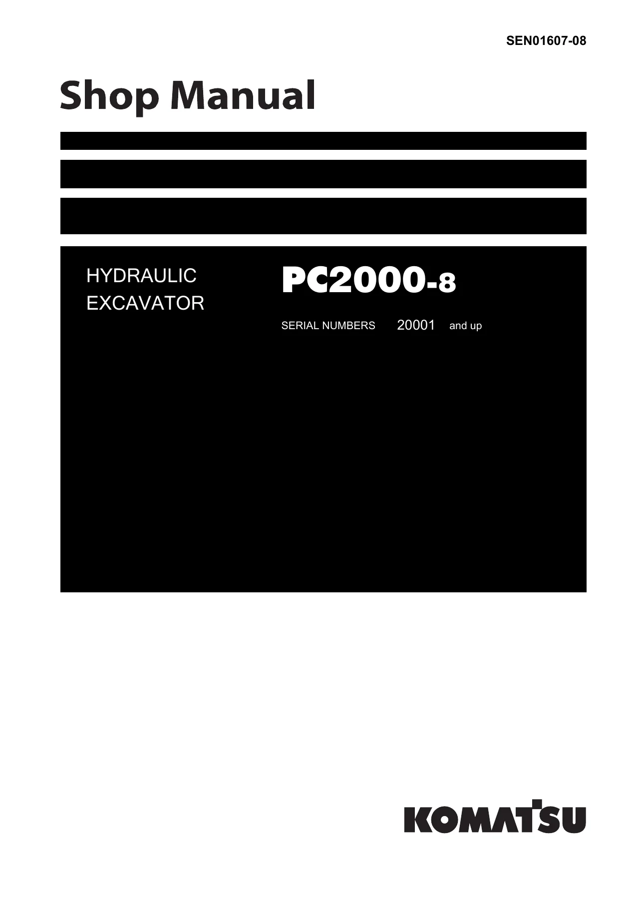
Komatsu PC2000-8 Hydraulic Excavator Shop Manual SEN01607-08 (Serial 20001 and Up) — PDF page 1 preview
Komatsu PC2000-8 Hydraulic Excavator Shop Manual SEN01607-08 (Serial 20001 and Up) — PDF page 62 preview
Komatsu PC2000-8 Hydraulic Excavator Shop Manual SEN01607-08 (Serial 20001 and Up) — PDF page 1445 preview

E-mode electrical troubleshooting starts from “monitor displays nothing,” no-start (engine does not turn), auto-decelerator and automatic warm-up, preheater, disabled work equipment / swing / travel, push-up and boom shockless functions, gauge and monitor faults, wiper, travel alarm, lamps, air conditioner, and step light. H-mode hydraulic and mechanical charts cover low speed or power of the whole machine, engine stall under load, no movement, pump noise, boom / arm / bucket power or no movement, hydraulic drift and time lag, heavy-lift and push-up functions, travel deviation and one-side travel failure, swing speed, overrun and shock, fan noise or overheating, and loading-shovel bottom-dump faults. S-mode engine charts cover hard starting, no start, poor pickup, stop during work, rough running, lack of power, black or blue smoke, oil consumption and contamination, fuel consumption, oil in coolant, low oil pressure, rising oil level, overheating, abnormal noise, and vibration.

Disassembly Weights and Shop Practice

Section 50 records the weights a crane operator actually needs. Power container assembly is 16,238 kg. Combined engine, PTO and hydraulic pump assembly is approximately 6,100 kg, with engine-mount bolts specified 824–1,030 Nm {84–105 kgm}, target 927 Nm {94.5 kgm}. Engine hood assembly is 210 kg. Hydraulic tank refill after service is approximately 1,300 ℓ. Coolant refill after cooling-system work is 180 ℓ. Ladder assembly is 170 kg. Special-tool lists and coating-material lists sit at the front of the disassembly section so the shop can stage stands, forcing screws, seal drivers, and sealants before the first hose comes off.

What This Manual Enables

The Komatsu PC2000-8 Hydraulic Excavator Shop Manual SEN01607-08 (Serial 20001 and Up) supports pressure setting and confirmation on the work-equipment, swing, travel, fan, and pilot circuits; diagnosis of VHMS, pump-controller, and dual-bank engine-controller faults; injector, supply-pump, and oil-seal replacement on the installed SAA12V140E-3; removal of the power container and the engine-PTO-pump stack; rebuild or exchange of control valves, PPC valves, swing and travel motors, center swivel joint, final drives, rollers, idlers, and hydraulic cylinders for both backhoe and loading shovel front ends; cab, monitor, and controller exchange; and tracing of the full hydraulic circuit plus the twelve-sheet electrical diagram set. Using the printed clearances, relief values, current ranges, and torque figures keeps a 200-tonne class excavator from being adjusted by guesswork. After payment the file is delivered as an instant PDF download with no shipping wait. Open it on a shop PC, tablet, or phone and print the pages needed for the job.
Reviews

There are no reviews yet.

Be the first to review “Komatsu PC2000-8 Hydraulic Excavator Shop Manual SEN01607-08 (Serial 20001 and Up)”

What Our Customers Say

★★★★★ Live reviews from customers
Loading customer reviews...
0
    0
    Your Cart
    Your cart is emptyReturn to Shop
    🛒
    Recently Purchased
    🕒 verified order