Komatsu PC228US-3, PC228USLC-3 Hydraulic Excavator Shop Manual SEBM023104 – PDF DOWNLOAD
Original price was: $51.95.$21.95Current price is: $21.95.
Komatsu PC228US-3, PC228USLC-3 Hydraulic Excavator Shop Manual
MACHINE MODEL SERIAL NUMBER
PC228US-3 20001 and up 00
PC228USLC-3 20001 and up
Description
Komatsu PC228US-3, PC228USLC-3 Hydraulic Excavator Shop Manual
FILE DETAILS:
Komatsu PC228US-3, PC228USLC-3 Hydraulic Excavator Shop Manual
Brands: Komatsu
Equipment Type: Hydraulic Excavator
Manuals Type: Shop Manual
Machine Model: PC228US-3, PC228USLC-3
Serial Number: 20001 and up
Book Code: SEBM023104
Language: English
Pages: 598
File Format: Portable Document Format (PDF)
DESCRIPTION:
Komatsu PC228US-3, PC228USLC-3 Hydraulic Excavator Shop Manual
FOREWORD:
General :
This shop manual has been prepared as an aid to improve the quality of repairs by giving the serviceman an accu- rate understanding of the product and by showing him the correct way to perform repairs and make judgements. Make sure you understand the contents of this manual and use it to full effect at every opportunity. This shop manual mainly contains the necessary technical information for operations performed in a service work- shop. For ease of understanding. the manual is divided into the following chapters; these chapters are further divided into the each main group of components.
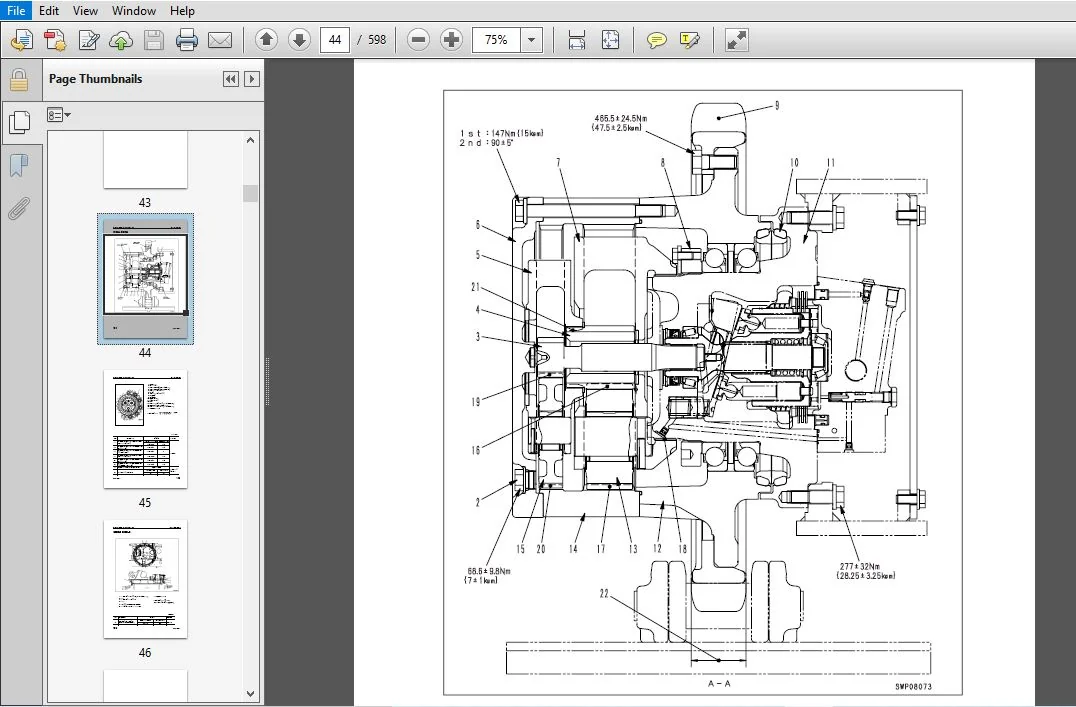
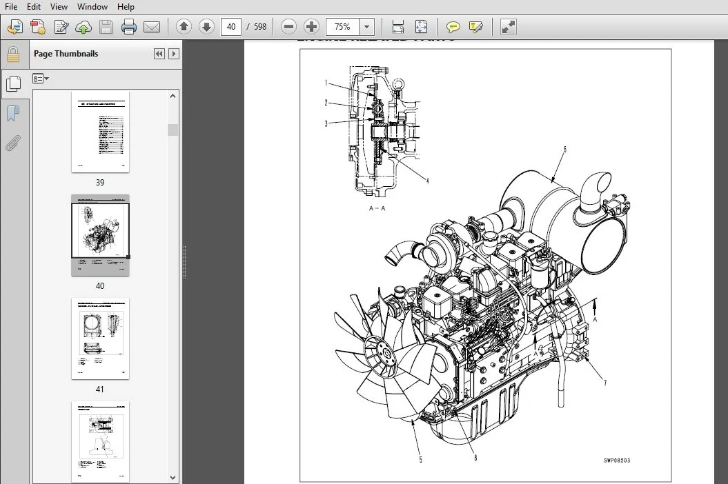
Structure and function:
This section explains the structure and function of each component It serves not only to give an under- standing of the structure, but also serves as reference material for troubleshooting. in addition, this section may contain hydraulic circuit diagrams, electric circuit diagrams, and maintenance standards.
Testing and adjusting:
This section explains checks to be made before and after performing repairs, as well as adjustments to be made at completion of the checks and repairs. Troubleshooting charts correlating “Problems‘ with “Causes‘ are also included in this section.
Disassembly and assembly:
This section explains the procedures for removing, installing, disassembling and assembling each compo- nent, as well as precautions for them.
Maintenance standard:
This section gives the judgment standards for inspection of disassembled parts. The contents of this section may be described in “Structure and function.
Others:
This section mainly gives hydraulic circuit diagrams and electric circuit diagrams. in addition, this section may give the specifications of attachments and options together.
TABLE OF CONTENTS:
Komatsu PC228US-3, PC228USLC-3 Hydraulic Excavator Shop Manual
COVER...............................................................................................................................................................................................  1
	CONTENTS........................................................................................................................................................................................  2
	LIST OF REVISED PAGES...........................................................................................................................................................................  3
	SAFETY..........................................................................................................................................................................................  7
		SAFETY NOTICE...............................................................................................................................................................................  7
			GENERAL PRECAUTIONS.....................................................................................................................................................................  7
			PREPARATIONS FOR WORK...................................................................................................................................................................  7
			PRECAUTIONS DURING WORK.................................................................................................................................................................  8
	FOREWORD........................................................................................................................................................................................  9
		GENERAL.....................................................................................................................................................................................  9
		HOW TO READ THE SHOP MANUAL................................................................................................................................................................. 10
		HOISTING INSTRUCTIONS....................................................................................................................................................................... 11
		METHOD OF DISASSEMBLING, CONNECTING PUSH-PULL TYPE COUPLER.................................................................................................................................. 12
		COATING MATERIALS........................................................................................................................................................................... 14
		STANDARD TIGHTENING TORQUE.................................................................................................................................................................. 16
		ELECTRIC WIRE CODE.......................................................................................................................................................................... 19
		CONVERSION TABLE............................................................................................................................................................................ 20
01 GENERAL.......................................................................................................................................................................................... 27
	SPECIFICATION DIMENSION DRAWINGS................................................................................................................................................................ 28
	SPECIFICATIONS.................................................................................................................................................................................. 30
	WEIGHT TABLE.................................................................................................................................................................................... 34
	FUEL, COOLANT, AND LUBRICANTS................................................................................................................................................................... 38
10 STRUCTURE AND FUNCTION........................................................................................................................................................................... 39
	ENGINE RELATED PARTS............................................................................................................................................................................ 40
	RADIATOR • OIL COOLER • AFTERCOOLER............................................................................................................................................................. 41
	POWER TRAIN..................................................................................................................................................................................... 42
	FINAL DRIVE..................................................................................................................................................................................... 44
	SWING CIRCLE.................................................................................................................................................................................... 46
	SWING MACHINERY................................................................................................................................................................................. 48
	TRACK FRAME • RECOIL SPRING..................................................................................................................................................................... 50
		IDLER....................................................................................................................................................................................... 52
		CARRIER ROLLER.............................................................................................................................................................................. 54
		TRACK ROLLER................................................................................................................................................................................ 55
	TRACK SHOE...................................................................................................................................................................................... 56
		TRIPLE GROUSER SHOE, ROAD LINER, SWAMP SHOE, FLAT SHOE...................................................................................................................................... 56
		TRIPLE GROUSER SHOE......................................................................................................................................................................... 59
	HYDRAULIC TANK.................................................................................................................................................................................. 60
	HYDRAULIC PUMP.................................................................................................................................................................................. 62
		HPV95 + 95.................................................................................................................................................................................. 62
		LS VALVE.................................................................................................................................................................................... 67
		PC VALVE.................................................................................................................................................................................... 67
		LS-EPC VALVE................................................................................................................................................................................ 80
	CONTROL VALVE................................................................................................................................................................................... 84
		VARIABLE PRESSURE COMPENSATION VALVE........................................................................................................................................................ 94
	CLSS............................................................................................................................................................................................ 96
		OUTLINE OF CLSS............................................................................................................................................................................. 96
	SELF PRESSURE REDUCING VALVE.................................................................................................................................................................... 99
	TRAVEL JUNCTION VALVE...........................................................................................................................................................................102
	BOOM HYDRAULIC DRIFT PREVENTION VALVE...........................................................................................................................................................104
	TRAVEL PPC SHUTTLE VALVE........................................................................................................................................................................107
	LIFT CHECK VALVE................................................................................................................................................................................109
	HOLDING VALVE...................................................................................................................................................................................110
	SWING MOTOR.....................................................................................................................................................................................116
	REVERSE PREVENTION VALVE........................................................................................................................................................................121
	CENTER SWIVEL JOINT.............................................................................................................................................................................123
	TRAVEL MOTOR....................................................................................................................................................................................124
	VALVE CONTROL...................................................................................................................................................................................133
	WORK EQUIPMENT • SWING PPC VALVE................................................................................................................................................................134
	TRAVEL PPC VALVE................................................................................................................................................................................138
	SERVICE PPC VALVE...............................................................................................................................................................................148
	PPC ACCUMULATOR.................................................................................................................................................................................151
	SOLENOID VALVE..................................................................................................................................................................................152
	HYDRAULIC CYLINDER..............................................................................................................................................................................154
		BOOM CYLINDER...............................................................................................................................................................................154
		ARM CYLINDER................................................................................................................................................................................154
		BUCKET CYLINDER.............................................................................................................................................................................154
	WORK EQUIPMENT..................................................................................................................................................................................156
		DIMENSION OF ARM............................................................................................................................................................................158
		DIMENSION OF BUCKET.........................................................................................................................................................................160
	ENGINE CONTROL..................................................................................................................................................................................162
		OPERATION OF SYSTEM.........................................................................................................................................................................164
			Starting engine.........................................................................................................................................................................164
			Engine speed control....................................................................................................................................................................164
			Stopping engine.........................................................................................................................................................................164
		COMPONENT...................................................................................................................................................................................165
			Fuel control dial.......................................................................................................................................................................165
			Governor motor..........................................................................................................................................................................166
			Engine throttle and pump controller.....................................................................................................................................................168
	ELECTRONIC CONTROL SYSTEM.......................................................................................................................................................................171
		Engine and Pump control function............................................................................................................................................................174
		Pump/Valve control function.................................................................................................................................................................180
		One-touch power maximizing function.........................................................................................................................................................182
		Auto-deceleration function..................................................................................................................................................................184
		Auto-warm-up/Overheat prevention function...................................................................................................................................................186
		Swing control function......................................................................................................................................................................188
		Travel control function.....................................................................................................................................................................190
		Boom stroke end electronic cushion function.................................................................................................................................................192
		ATT PPC throttle function (Optional)........................................................................................................................................................194
		System component parts......................................................................................................................................................................195
			Engine revolution sensor................................................................................................................................................................195
			PPC oil pressure switch.................................................................................................................................................................196
			Pump pressure sensor....................................................................................................................................................................197
			Potentiometer...........................................................................................................................................................................198
			Resistor................................................................................................................................................................................199
	MONITORING SYSTEM...............................................................................................................................................................................200
		Monitor panel...............................................................................................................................................................................201
		Display section of monitor..................................................................................................................................................................202
		Mode selector switches......................................................................................................................................................................206
	SENSOR..........................................................................................................................................................................................207
		Engine oil level sensor.....................................................................................................................................................................208
		Engine oil pressure sensor (For low pressure)...............................................................................................................................................208
		Coolant temperature sensor..................................................................................................................................................................208
		Fuel level sensor...........................................................................................................................................................................209
		Air cleaner clogging sensor.................................................................................................................................................................209
20 TESTING, ADJUSTING,AND TROUBLESHOOTING...........................................................................................................................................................211
	STANDARD VALUE TABLE FOR ENGINE.................................................................................................................................................................212
	STANDARD VALUE TABLE FOR CHASSIS................................................................................................................................................................213
	STANDARD VALUE TABLE FOR ELECTRICAL RELATED PARTS...............................................................................................................................................223
	TESTING AND ADJUSTING...........................................................................................................................................................................231
		TOOLS FOR TESTING, ADJUSTING, AND TROUBLESHOOTING...........................................................................................................................................232
		MEASURING ENGINE SPEED......................................................................................................................................................................234
		MEASURING EXHAUST GAS COLOR.................................................................................................................................................................235
		ADJUSTING VALVE CLEARANCE...................................................................................................................................................................236
		MEASURING COMPRESSION PRESSURE..............................................................................................................................................................237
		MEASURING BLOW-BY PRESSURE..................................................................................................................................................................237
		FUEL INJECTION TIMING.......................................................................................................................................................................238
		MEASURING ENGINE OIL PRESSURE...............................................................................................................................................................239
		BELT TENSION FOR AIR CONDITIONER COMPRESSOR.................................................................................................................................................240
		MEASURING SPEED SENSOR......................................................................................................................................................................240
		GOVERNOR MOTOR LEVER STROKE.................................................................................................................................................................241
		HYDRAULIC PRESSURE IN WORK EQUIPMENT, SWING TRAVEL CIRCUIT..................................................................................................................................242
		PC VALVE OUTPUT PRESSURE (SERVO PISTON INPUT PRESSURE)......................................................................................................................................245
		LS VALVE OUTPUT PRESSURE (SERVO PISTON INPUT PRESSURE) AND LS DIFFERENTIAL PRESSURE.........................................................................................................247
		CONTROL CIRCUIT OIL PRESSURE................................................................................................................................................................250
		MEASURING SOLENOID VALVE OUTPUT PRESSURE....................................................................................................................................................251
		MEASURING PPC VALVE OUTPUT PRESSURE.........................................................................................................................................................254
		ADJUSTING WORK EQUIPMENT• SWING PPC VALVE...................................................................................................................................................255
		TESTING TRAVEL DEVIATION....................................................................................................................................................................256
		TESTING LOCATIONS CAUSING HYDRAULIC DRIFT OF WORK EQUIPMENT.................................................................................................................................257
		MEASURING SWING, TRAVEL MOTOR OIL LEAKAGE...................................................................................................................................................258
		TESTING CLEARANCE OF SWING CIRCLE BEARING...................................................................................................................................................259
		TESTING WEAR OF SPROCKET....................................................................................................................................................................260
		TRACK SHOE TENSION..........................................................................................................................................................................261
		BLEEDING AIR................................................................................................................................................................................262
			Bleeding air from pump..................................................................................................................................................................262
			Bleeding air from hydraulic cylinders...................................................................................................................................................263
			Bleeding air from swing motor...........................................................................................................................................................263
			Bleeding air from travel motor..........................................................................................................................................................263
		PROCEDURE FOR REPLACEMENT OF BOOM ANGLE POTENTIOMETER.......................................................................................................................................264
		PROCEDURE FOR CHECKING DIODE................................................................................................................................................................265
	TROUBLESHOOTING.................................................................................................................................................................................267
		POINTS TO REMEMBER WHEN TROUBLESHOOTING.....................................................................................................................................................268
		SEQUENCE OF EVENTS IN TROUBLESHOOTING.......................................................................................................................................................269
		POINTS TO REMEMBER WHEN CARRYING OUT MAINTENANCE............................................................................................................................................270
			PRECAUTIONS WHEN HANDLING ELECTRIC EQUIPMENT............................................................................................................................................270
			Points to remember when troubleshooting electric circuits...............................................................................................................................275
			POINTS TO REMEMBER WHEN HANDLINGHYDRAULIC EQUIPMENT.....................................................................................................................................276
		CHECKS BEFORE TROUBLESHOOTING...............................................................................................................................................................278
		CONNECTOR TYPES AND MOUNTING LOCATIONS......................................................................................................................................................279
		CONNECTION TABLE FOR CONNECTOR PIN NUMBERS..................................................................................................................................................286
		EXPLANATION OF CONTROL MECHANISM FOR ELECTRICAL SYSTEM......................................................................................................................................301
		DISPLAY METHOD AND SPECIAL FUNCTIONS OF MONITOR PANEL.......................................................................................................................................302
		METHOD OF USING JUDGEMENT TABLE.............................................................................................................................................................318
		METHOD OF USING TROUBLESHOOTING CHARTS......................................................................................................................................................320
		DETAILS OF TROUBLESHOOTING AND TROUBLESHOOTING PROCEDURE....................................................................................................................................322
		TROUBLESHOOTING OF COMMUNICATIONS ABNORMALITY (N MODE)......................................................................................................................................327
			N-1 [E218] Communications abnormality...................................................................................................................................................328
		TROUBLESHOOTING OF ENGINE THROTTLE AND PUMP CONTROLLER (GOVERNOR CONTROL SYSTEM) (E MODE)...................................................................................................329
			POINTS TO REMEMBER WHEN CARRYING OUT TROUBLESHOOTING OF ENGINE THROTTLE AND PUMP CONTROLLER SYSTEM......................................................................................330
			ACTION TAKEN BY CONTROLLER WHEN ABNORMALITY OCCURS AND PROBLEMS ON MACHINE..............................................................................................................332
			JUDGEMENT TABLE FOR ENGINE THROTTLE AND PUMP CONTROLLER (GOVERNOR CONTROL SYSTEM) AND ENGINE RELATED PARTS..............................................................................336
			ELECTRICAL CIRCUIT DIAGRAM FOR E MODE...................................................................................................................................................338
			E-1 Abnormality in engine throttle and pump controller power source (controller LED is OFF).............................................................................................340
			E-2 [E308] Abnormality in fuel control dial input value is displayed....................................................................................................................341
			E-3 [E317] Abnormality (disconnection) in governor drive system displayed...............................................................................................................342
			E-4 [E318] Abnormality (short circuit) in motor drive system is displayed...............................................................................................................343
			E-5 [E306] Abnormality in feedback potentiometer system is displayed....................................................................................................................344
			E-6 [E315] Abnormality (short circuit) in battery relay output system is displayed......................................................................................................345
			E-7 [E316] Abnormality (step-out) in governor motor is displayed........................................................................................................................346
			E-8 Engine does not start...............................................................................................................................................................348
			E-9 Engine speed is irregular...........................................................................................................................................................352
				a) Idling speed is irregular........................................................................................................................................................352
				b) There is hunting.................................................................................................................................................................354
			E-10 Lack of power (engine high idling speed is too low)................................................................................................................................356
			E-11 Engine does not stop...............................................................................................................................................................358
			E-12 Defective operation of battery relay system (engine does not stop).................................................................................................................360
		TROUBLESHOOTING OF ENGINE THROTTLE AND PUMP CONTROLLER (PUMP CONTROL SYSTEM) (C MODE).......................................................................................................363
			POINTS TO REMEMBER WHEN TROUBLESHOOTING PUMP CONTROLLER SYSTEM..........................................................................................................................364
			ACTION TAKEN BY THE CONTROLLER WHEN ABNORMALITY OCCURS AND PROBLEMS ON MACHINE..........................................................................................................366
			JUDGEMENT TABLE FOR ENGINE THROTTLE • PUMP CONTROLLER (PUMP CONTROL SYSTEM) AND HYDRAULIC RELATED PARTS.................................................................................376
			ELECTRICAL CIRCUIT DIAGRAM FOR C MODE...................................................................................................................................................378
			C-1 Abnormality in controller power source system (controller LED is off)...............................................................................................................380
			C-2 ([E232] Short circuit in PC-EPC solenoid system) is displayed.......................................................................................................................381
			C-3 ([E233] Disconnection in PC-EPC solenoid system) is displayed.......................................................................................................................382
			C-4 ([E203] Short circuit in swing holding brake solenoid system) is displayed..........................................................................................................383
			C-5 ([E213] Disconnection in swing holding brake solenoid system) is displayed..........................................................................................................385
			C-6 ([E234] Short circuit in boom RAISE throttle EPC solenoid system) is displayed......................................................................................................387
			C-7 ([E235] Disconnection in boom RAISE throttle EPC solenoid system) is displayed......................................................................................................388
			C-8 ([E204] Short circuit in pump merge/divider solenoid system) is displayed...........................................................................................................389
			C-9 ([E214] Disconnection in pump merge/divider solenoid system) is displayed...........................................................................................................390
			C-10([E206] Short circuit in travel speed selector system) is displayed.................................................................................................................391
			C-11 ([E216] Disconnection in travel speed solenoid system) is displayed................................................................................................................392
			C-12 ([E205] Short circuit in 2-stage relief solenoid system) is displayed..............................................................................................................393
			C-13 ([E205] Disconnection in 2-stage relief solenoid system) is displayed..............................................................................................................394
			C-14 ([E217] Machine Model selection input error) is displayed..........................................................................................................................395
			C-15 ([E222] Short circuit in LS-EPC solenoid system) is displayed......................................................................................................................396
			C-16 ([E223] Disconnection in LS-EPC solenoid system) is displayed......................................................................................................................397
			C-17 ([E223] Abnormality in front pump pressure sensor system) is displayed.............................................................................................................398
			C-18 ([E225] Abnormality in rear pump pressure sensor system) is displayed..............................................................................................................399
			C-19 ([E226] Abnormality in pressure sensor power system) is displayed..................................................................................................................400
			C-20 ([E201] Short circuit in travel junction solenoid system) is displayed.............................................................................................................401
			C-21 ([E211] Disconnection in travel junction solenoid system) is displayed.............................................................................................................402
			C-22 ([E227] Abnormality in engine speed sensor) is displayed...........................................................................................................................403
			C-23 ([E241] Abnormality in boom angle potentiometer system input value) is displayed...................................................................................................404
			C-24 ([E255] Abnormality in boom angle potentiometer compensation value (outside compensation range) is displayed.......................................................................405
			C-25 ([E256] Abnormality in check sum is displayed......................................................................................................................................405
			C-26 ([E313] Abnormality in automatic greasing is displayed.............................................................................................................................405
			C-27 [E313] Abnormality in ATT-EPC solenoid system......................................................................................................................................406
		TROUBLESHOOTING OF ENGINE THROTTLE AND PUMP CONTROLLER (INPUT SIGNAL SYSTEM) (F MODE).......................................................................................................407
			F - MODE ELECTRICAL CIRCUIT DIAGRAM.....................................................................................................................................................408
			F-1 Bit pattern 20-(1) Swing oil pressure switch ON display does not light up...........................................................................................................410
			F-2 Bit pattern 20-(2) Travel pressure switch ON display does not light up..............................................................................................................411
			F-3 Bit pattern 20-(3) Boom LOWER oil pressure switch ON display does not light up......................................................................................................412
			F-4 Bit pattern 20-(4) Boom RAISE oil pressure switch ON display does not light up......................................................................................................413
			F-5 Bit pattern 20-(5) Arm IN oil pressure switch ON display does not light up..........................................................................................................414
			F-6 Bit pattern 20-(6) Arm OUT oil pressure switch ON display does not light up.........................................................................................................415
			F-7 Bit pattern 21-(1) Bucket CURL oil pressure switch ON display does not light up.....................................................................................................416
			F-8 Bit pattern 21-(2) Bucket DUMP oil pressure switch ON display does not light up.....................................................................................................417
			F-9 Bit pattern 21-(4) Service pressure switch ON display does not light up.............................................................................................................418
			F-10 Bit pattern 21-(5) Travel steering pressure ON display switch does not light up....................................................................................................419
			F-11 Bit pattern 22-(3) L. H. knob switch ON display does not light up..................................................................................................................420
			F-12 Bit pattern 22-(4) Emergency swing holding brake release switch ON display does not light up.......................................................................................421
			F-13 Bit pattern 22-(5) Swing lock switch ON display does not light up..................................................................................................................422
			F-14 Bit pattern 27-(6) Kerosene mode connection display does not light up..............................................................................................................423
		TROUBLESHOOTING OF HYDRAULIC AND MECHANICAL SYSTEM (H MODE).................................................................................................................................425
			TABLE OF FAILURE MODES AND CAUSES FOR HYDRAULIC AND MECHANICAL SYSTEM ..................................................................................................................426
			PUMP MERGE/DIVIDER LOGIC................................................................................................................................................................430
			ON/OFF SOLENOID ACTUATION TABLE.........................................................................................................................................................431
			H-1 Speeds of all work equipment, swing, travel are slow or lack power..................................................................................................................432
			H-2 There is excessive drop in engine speed, or engine stalls...........................................................................................................................434
			H-3 No work equipment, travel, swing move...............................................................................................................................................435
			H-4 Abnormal noise generated (around pump)..............................................................................................................................................435
			H-5 Auto-deceleration does not work (PPC Shuttle valve is equipped only in travel PPC valve)............................................................................................436
			H-6 Fine control ability is poor or response is poor....................................................................................................................................436
			H-7 Boom is slow or lacks power.........................................................................................................................................................438
			H-8 Arm is slow or lacks power..........................................................................................................................................................440
			H-9 Bucket is slow or lacks power.......................................................................................................................................................442
			H-10 Work equipment (boom, arm, bucket) does not move (but travel and swing are normal).................................................................................................443
			H-11 Excessive hydraulic drift..........................................................................................................................................................443
			H-12 Excessive time lag (engine at low idling)..........................................................................................................................................444
			H-13 Other equipment moves when single circuit is relieved..............................................................................................................................444
			H-14 Lack of power when pressure rises..................................................................................................................................................444
			H-15 In compound operations, work equipment with larger load is slow....................................................................................................................445
			H-16 In swing + boom RAISE, boom RAISE is slow..........................................................................................................................................445
			H-17 In swing + travel, travel speed drops excessively..................................................................................................................................445
			H-18 Travel deviation...................................................................................................................................................................446
			H-19 Travel speed is slow...............................................................................................................................................................447
			H-20 Steering is difficult to turn or lacks power.......................................................................................................................................448
			H-21 Travel speed does not switch or is faster than specified speed.....................................................................................................................450
			H-22 Travel does not move (one side only)...............................................................................................................................................450
			H-23 Does not swing.....................................................................................................................................................................451
			H-24 Swing acceleration is poor or swing speed is slow..................................................................................................................................452
			H-25 Excessive overrun when stopping swing..............................................................................................................................................453
			H-26 Excessive shock when stopping swing (one direction only)...........................................................................................................................453
			H-27 Excessive abnormal noise when stopping swing.......................................................................................................................................454
			H-28 Excessive hydraulic drift of swing.................................................................................................................................................455
		TROUBLESHOOTING OF MONITOR PANEL SYSTEM (M MODE)............................................................................................................................................457
			ACTION TAKEN BY MONITOR PANEL WHEN ABNORMALITYOCCURS AND PROBLEMS ON MACHINE............................................................................................................458
			M-MODE ELECTRICAL CIRCUIT DIAGRAM.......................................................................................................................................................460
			M-1 [E101] (Abnormality in error data history) is displayed.............................................................................................................................462
			M-2 [E104] (Air cleaner clogging detected) is displayed.................................................................................................................................463
			M-3 [E108] (Engine water temperature 105° detected) is not displayed....................................................................................................................463
			M-4 [E114] (Short circuit in wiper motor normal rotation output) is displayed...........................................................................................................463
			M-5 [E115] (Short circuit in wiper motor reverse rotation output) is displayed..........................................................................................................463
			M-6 [E116] (Short circuit with power supply in washer output) is displayed..............................................................................................................463
			M-7 [E117] (Wiping failure continues for 10 seconds) is displayed.......................................................................................................................463
			M-8 [E118] (Storing wiper blade failure continues for 10 seconds) is displayed..........................................................................................................463
			M-9 When starting switch is turned ON, none of the lamps on the monitor panel light up for 3 seconds....................................................................................464
			M-10 When starting switch is turned ON, monitor panel lamps all stay lighted up and do not go out.......................................................................................465
			M-11 When starting switch is turned ON (engine stopped), basic check item flashes.......................................................................................................465
			M-12 Preheating is not being used but (preheating monitor) lights up....................................................................................................................467
			M-13 When starting switch is ON and engine is started, basic check item flashes.........................................................................................................468
			M-14 When starting switch is turned ON (engine stopped), caution items, emergency items flash, engine oil pressure lamps do not light up................................................470
			M-15 When starting switch is turned ON and engine is started, caution items, emergency items flash (when there is no abnormality in engine or items to check before troubleshooting)....472
			M-16 When starting switch is turned ON (engine stopped), buzzer does not sound for 1 second - Caution item lamp flashes but buzzer does not sound.......................................475
			M-17 Night lighting on monitor panel does not light up (liquid crystal display is normal)...............................................................................................476
			M-18 Coolant temperature gauge always displays low......................................................................................................................................477
			M-19 Coolant temperature gauge does not give any display (none of gauge elements light up during operation).............................................................................477
			M-20 Fuel level gauge always displays full..............................................................................................................................................478
			M-21 Fuel level gauge does not give display.............................................................................................................................................478
			M-22 Swing lock switch is turned ON (lock) but (swing lock monitor) does not light up...................................................................................................479
			M-23 Service meter does not advance when engine is running..............................................................................................................................479
			M-24 Defective fuel level sensor system.................................................................................................................................................480
			M-25 Defective coolant temperature sensor system........................................................................................................................................481
			M-26 Defective engine oil level sensor system...........................................................................................................................................482
			M-27 Wiper does not work, or switch is not being used but wiper is actuated.............................................................................................................483
			M-28 Washer motor does not work, or washer switch is not being used but washer motor is actuated........................................................................................486
30 DISASSEMBLY AND ASSEMBLY.........................................................................................................................................................................487
	METHOD OF USING MANUAL..........................................................................................................................................................................489
	PRECAUTIONS WHEN CARRYING OUT OPERATION.........................................................................................................................................................491
	SPECIAL TOOL LIST...............................................................................................................................................................................494
		SKETCHES OF SPECIAL TOOLS...................................................................................................................................................................497
	ENGINE ASSEMBLY.................................................................................................................................................................................500
		REMOVAL OF..................................................................................................................................................................................500
		INSTALLATION OF.............................................................................................................................................................................502
	ENGINE FRONT SEAL...............................................................................................................................................................................503
		REMOVAL OF..................................................................................................................................................................................503
		INSTALLATION OF.............................................................................................................................................................................503
	ENGINE REAR SEAL................................................................................................................................................................................505
		REMOVAL OF..................................................................................................................................................................................505
		INSTALLATION OF.............................................................................................................................................................................506
	RADIATOR ASSEMBLY...............................................................................................................................................................................507
		REMOVAL OF..................................................................................................................................................................................507
		INSTALLATION OF.............................................................................................................................................................................508
	HYDRAULIC OIL COOLER ASSEMBLY...................................................................................................................................................................509
		REMOVAL OF..................................................................................................................................................................................509
		INSTALLATION OF.............................................................................................................................................................................510
	AFTERCOOLER ASSEMBLY............................................................................................................................................................................511
		REMOVAL OF..................................................................................................................................................................................511
		INSTALLATION OF.............................................................................................................................................................................511
	FUEL TANK ASSEMBLY..............................................................................................................................................................................512
		REMOVAL OF..................................................................................................................................................................................512
		INSTALLATION OF.............................................................................................................................................................................512
	CENTER SWIVEL JOINT ASSEMBLY....................................................................................................................................................................513
		REMOVAL OF..................................................................................................................................................................................513
		INSTALLATION OF.............................................................................................................................................................................514
		DISASSEMBLY OF..............................................................................................................................................................................515
		ASSEMBLY OF.................................................................................................................................................................................515
	FINAL DRIVE, TRAVEL MOTOR ASSEMBLY..............................................................................................................................................................516
		REMOVAL OF..................................................................................................................................................................................516
		INSTALLATION OF.............................................................................................................................................................................516
		DISASSEMBLY OF..............................................................................................................................................................................517
		ASSEMBLY OF.................................................................................................................................................................................520
	SWING MOTOR AND SWING MACHINERY ASSEMBLY........................................................................................................................................................526
		REMOVAL OF..................................................................................................................................................................................526
		INSTALLATION OF.............................................................................................................................................................................526
		SWING MACHINERY ASSEMBLY....................................................................................................................................................................527
			DISASSEMBLY OF..........................................................................................................................................................................527
			ASSEMBLY OF.............................................................................................................................................................................529
	REVOLVING FRAME ASSEMBLY........................................................................................................................................................................535
		REMOVAL OF..................................................................................................................................................................................535
		INSTALLATION OF.............................................................................................................................................................................536
	SWING CIRCLE ASSEMBLY...........................................................................................................................................................................536
		REMOVAL OF..................................................................................................................................................................................536
		INSTALLATION OF.............................................................................................................................................................................537
	RECOIL SPRING ASSEMBLY..........................................................................................................................................................................538
		DISASSEMBLY OF..............................................................................................................................................................................538
		ASSEMBLY OF.................................................................................................................................................................................539
	IDLER ASSEMBLY..................................................................................................................................................................................540
		ASSEMBLY....................................................................................................................................................................................540
	TRACK ROLLER ASSEMBLY...........................................................................................................................................................................542
		ASSEMBLY OF.................................................................................................................................................................................542
	TRACK SHOE ASSEMBLY.............................................................................................................................................................................544
		STEEL SHOE..................................................................................................................................................................................544
			EXPANSION OF............................................................................................................................................................................544
			INSTALLATION OF.........................................................................................................................................................................544
		ROAD LINER SHOE.............................................................................................................................................................................545
			EXPANSION OF............................................................................................................................................................................545
			INSTALLATION OF.........................................................................................................................................................................545
	HYDRAULIC TANK ASSEMBLY.........................................................................................................................................................................546
		REMOVAL OF..................................................................................................................................................................................546
		INSTALLATION OF.............................................................................................................................................................................546
	HYDRAULIC PUMP ASSEMBLY.........................................................................................................................................................................547
		REMOVAL OF..................................................................................................................................................................................547
		INSTALLATION OF.............................................................................................................................................................................548
	CONTROL VALVE ASSEMBLY..........................................................................................................................................................................549
		REMOVAL OF..................................................................................................................................................................................549
		INSTALLATION OF.............................................................................................................................................................................551
		DISASSEMBLY OF..............................................................................................................................................................................552
		ASSEMBLY OF.................................................................................................................................................................................558
	PUMP MERGE-DIVIDER VALVE/SELF-PRESSURE REDUCING VALVE/TRAVEL JUNCTION VALVE ASSEMBLY............................................................................................................564
		DISASSEMBLY OF..............................................................................................................................................................................564
		ASSEMBLY OF.................................................................................................................................................................................565
	MAIN RELIEF VALVE ASSEMBLY......................................................................................................................................................................566
		DISASSEMBLY OF..............................................................................................................................................................................566
		ASSEMBLY OF.................................................................................................................................................................................566
	WORK EQUIPMENT PPC VALVE ASSEMBLY (PPC VALVE FOR BOOM, BUCKET, ARM, SWING CONTROL)..............................................................................................................567
		DISASSEMBLY OF..............................................................................................................................................................................567
	TRAVEL PPC VALVE ASSEMBLY.......................................................................................................................................................................568
		DISASSEMBLY OF..............................................................................................................................................................................568
		ASSEMBLY OF.................................................................................................................................................................................568
	WORK EQUIPMENT ASSEMBLY.........................................................................................................................................................................569
		REMOVAL OF..................................................................................................................................................................................569
		INSTALLATION OF.............................................................................................................................................................................570
	OPERATOR'S CAB ASSEMBLY.........................................................................................................................................................................571
		REMOVAL OF..................................................................................................................................................................................571
		INSTALLATION OF.............................................................................................................................................................................572
	FLOOR FRAME ASSEMBLY............................................................................................................................................................................573
		REMOVAL OF..................................................................................................................................................................................573
		INSTALLATION OF.............................................................................................................................................................................574
	AIR CONDITIONER COMPRESSOR ASSEMBLY.............................................................................................................................................................575
		REMOVAL OF..................................................................................................................................................................................575
		INSTALLATION OF.............................................................................................................................................................................575
	AIR CONDITIONER CONDENSER ASSEMBLY..............................................................................................................................................................576
		REMOVAL OF..................................................................................................................................................................................576
		INSTALLATION OF.............................................................................................................................................................................576
	AIR CONDITIONER UNIT ASSEMBLY...................................................................................................................................................................576
		REMOVAL OF..................................................................................................................................................................................576
		INSTALLATION OF.............................................................................................................................................................................578
	COUNTERWEIGHT ASSEMBLY..........................................................................................................................................................................578
		REMOVAL, INSTALLATION OF....................................................................................................................................................................578
		Removal of maintenance counterweight assembly (above pump)..................................................................................................................................579
		Installation of maintenance counterweight assembly (above pump).............................................................................................................................579
		Removal of counterweight assembly (including central counterweight at rear of engine and counterweight above pump)..........................................................................579
		Installation of counterweight assembly (including central counterweight at rear of engine and counterweight above pump).....................................................................579
	MONITOR PANEL ASSEMBLY..........................................................................................................................................................................580
		REMOVAL OF..................................................................................................................................................................................580
		INSTALLATION OF.............................................................................................................................................................................580
90 OTHERS...........................................................................................................................................................................................581
	HYDRAULIC CIRCUIT DIAGRAM.......................................................................................................................................................................583
		STANDARD MACHINE............................................................................................................................................................................583
		ARM CRANE TYPE MACHINE......................................................................................................................................................................585
	ELECTRICAL CIRCUIT DIAGRAM......................................................................................................................................................................587
		STANDARD MACHINE (1/5)......................................................................................................................................................................587
		STANDARD MACHINE (2/5)......................................................................................................................................................................589
		STANDARD MACHINE (3/5)......................................................................................................................................................................591
		STANDARD MACHINE (4/5)......................................................................................................................................................................593
		ARM CRANE TYPE MACHINE (5/5)................................................................................................................................................................595
		ELECTRICAL CIRCUIT DIAGRAM FOR AIR CONDITIONER..............................................................................................................................................597
KOMATSU PC228US-3, PC228USLC-3 HYDRAULIC EXCAVATOR SHOP MANUAL SEBM023104 – PDF DOWNLOAD:
IMAGES PREVIEW OF THE MANUAL:
PLEASE NOTE:
- This is the same manual used by the DEALERSHIPS to SERVICE your vehicle.
- The manual can be all yours – Once payment is complete, you will be taken to the download page from where you can download the manual. All in 2-5 minutes time!!
- Need any other service / repair / parts manual, please feel free to contact us at heydownloadss @gmail.com . We may surprise you with a nice offer


Donovan Roberto –