
Komatsu PC240LC-11E0 PC240NLC-11E0 Parts Book UENPC00662 Serial K75001-up
Original price was: $32.95.$18.95Current price is: $18.95.
Komatsu parts book UENPC00662 for PC240LC-11E0 and PC240NLC-11E0 excavators from serial K75001 and up, with SAA6D107E-3A engine coverage from serial 22344728 and up. Illustrated figure pages list part numbers, names, quantities, interchange codes, and serial applicability for engine, aftertreatment, hydraulics, cab, undercarriage, and work equipment.
Description
Komatsu PC240LC-11E0 PC240NLC-11E0 Parts Book UENPC00662 Serial K75001-up
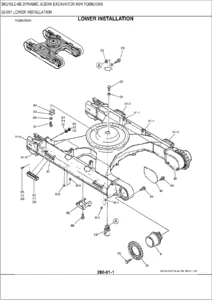
The Komatsu PC240LC-11E0 PC240NLC-11E0 Parts Book UENPC00662 Serial K75001-up is the illustrated spare-parts catalog for the long-track PC240LC-11E0 and narrow-track PC240NLC-11E0 machines built from machine serial K75001 and up. Engine listings follow the SAA6D107E-3A from engine serial 22344728 and up. Each figure pairs an exploded drawing with an index table so a parts clerk or technician can match a component on the machine to a part number, description, quantity, and serial break before placing an order.
The foreword tells the buyer exactly what to quote when ordering: part number, part name, quantity, machine model code, machine serial number, engine serial number, and service meter reading. Standard hardware is listed together with optional equipment and attachments, so the same catalog covers both the base machine and the many configuration splits that appear later in the contents (tool control, two-piece boom, super long front, demolition cab, LC Demo packages, and more).
File Details
- Manual type: Parts Book
- Brand / models: Komatsu PC240LC-11E0, PC240NLC-11E0
- Engine: SAA6D107E-3A
- Document number: UENPC00662
- Rights date shown: 09.12.2020
- Language: English listings with multilingual foreword pages
- Page count: 1482
- File format: PDF
How the Figures and Codes Work
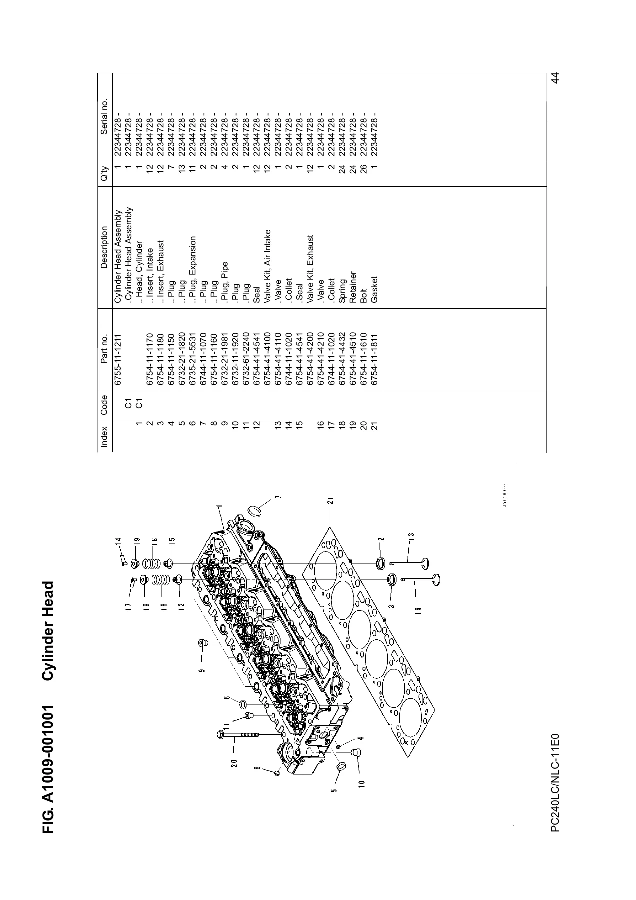
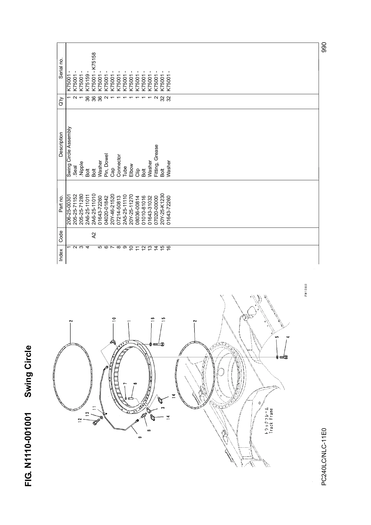
Open any figure in the Komatsu PC240LC-11E0 PC240NLC-11E0 Parts Book UENPC00662 Serial K75001-up and you will see a drawing first, then a parts list in index-number order. The figure number (FIG.) identifies the page group; it is not a spare-part number and the numbers are not always continuous. Columns give Index, Code, Part Number, Description, Qty, and Serial Numbers.
Interchange and supply codes printed in the book include:
- A1 — this part and the line immediately above are interchangeable
- A2 — the part in the line above can be used instead of this part
- A3 — this part can be used instead of the line immediately above
- A4 — the part named in the description can replace this part if used as a set
- B1 / B2 — discontinued items, with the substitute part or set identified
- C1 — not sold as an individual part; supplied as an assembly
- C2 — supplied for authorized Komatsu distributors only, as an assembly
- C3 — semi-finished part that needs additional work before installation
Component names under an assembly are indented with a leading mark. A kit callout points the reader to the FIELD REPAIR SERVICE PARTS section. Abbreviations used in descriptions include D (diameter), L (length), LHS / RHS, T (thickness), and W (width). Quantity is per machine unless the line sits under an assembly; AR means as required. Serial numbers in parentheses apply only to the equipment shown on that figure.
Machine, Engine, and Configuration Breaks
Cover identity is unambiguous: PC240LC/NLC-11E0, machine serial K75001 and up, engine SAA6D107E-3A serial 22344728 and up. Inside the lists, further serial windows split cab generations, lamps, auto-grease arms, and work equipment. Examples printed in the contents include ROPS cab groups for #K75001–K75053 versus Gateway cab groups from #K75054-, demolition cab groups for #K75001–K75090 and #K75091-, super-long-front cab groups for #K75001–K75045 and #K75046-, LED lamp packages around #K75228 / #K75229, tilt rotator from #K75232-, and arm auto-grease splits at #K75167 / #K75168.
Track-frame type is called out as Long Track Frame (LC) or Narrow Track Frame Type (NLC) on travel piping, track rollers, shoes, roller guards, and marks/plates. Work-equipment pages distinguish a 5900 mm heavy-duty boom, straight boom, two-piece boom (first and second boom), and an 18 m super long front, with arms listed at 2000 mm, 2500 mm, 3000 mm, and 3500 mm, including FHQC and breaker-clamshell variants.
Engine, Aftertreatment, and Engine-Room Groups
Engine volume pages start at the cylinder head and move through the block, lubrication, fuel, cooling, and electrical groups. Cylinder-head related figures cover the head and cover, air intake manifold and connector, air cleaner, exhaust manifold and mounting, Komatsu Variable Geometry Turbocharger (KVGT) and its oil piping, heat shield, EGR valve and cooler with air and water piping, Komatsu Closed Crankcase Ventilation (KCCV), coolant piping, exhaust connector clamp, AdBlue/DEF related parts, and the Komatsu Diesel Particulate Filter (KDPF) and SCR assembly including the AdBlue/DEF mixing tube.
Cylinder-block figures include rear and front gear covers, lubrication oil pump, 60 Amp and 90 Amp alternator spare parts, rocker arm, accessory drive pulley, flywheel housing and flywheel, oil pan and drain, oil level sensor and gauge, cylinder block, breather parts, crankshaft, vibration damper, piston and connecting rod, and rear gear housing. Lubrication continues with the oil filter and piping plus the oil cooler. Fuel figures list the prefilter, filter piping and cover, filter cartridge, drain piping, and related fuel-system parts. Cooling figures show the fan drive pulley, fan, spacer, belt tensioner, water pump and mounting, 90 Amp alternator drive belt, inlet and outlet connectors, thermostat, and coolant heater plug. Electrical engine items include the 90 Amp alternator inner parts and mounting, 5.5 kW starting motor and mounting, wiring harness, and related bolts. Performance parts pages isolate camshaft, injector, connector, and common-rail items, plus the engine control module. Field-repair kit pages and engine-related chassis items (damper, remote filter parts, elbow, engine mounting, air-intake connectors, and KDPF/SCR mounting, guards, sensors, drain piping, tubes and brackets) sit immediately after the engine marks section.
Cooling Package, Fuel Tank, DEF, and Machine Electrics
Chassis cooling-system figures cover the radiator, oil cooler, shroud, aftercooler, fuel cooler and condenser, aftercooler and radiator piping, fan guards, oil-cooler piping, and sub-tank. Fuel-system chassis pages list the fuel tank, piping, brackets and clips, filter mounting, and remote drain. AdBlue/DEF coverage continues with the tank frame, supply-module mounting, tank and sensor, suction tube, dosing-module coolant hose, tank coolant piping, and pressure hose.
Electrical-system figures begin with the EU battery and then split starting and main wiring-harness clamps, engine harnesses, working-lamp harnesses, tilt rotator wiring, additional working and LED lamps on cab top, deck, boom, boom-raise cylinder, and counterweight, plus rear work lamps, beacon and LED lightbar beacon, horn, travel alarm, and Komvision cover, harness, controller, and right-side, left-side, and rear cameras.
Hydraulics, Frame, Cab, and Undercarriage
The hydraulic section is the largest block in this PC240LC-11E0 / PC240NLC-11E0 parts catalog. It opens with the hydraulic tank for tool control and two-tool-control fittings, then walks through 7-spool one-additional-actuator valves, 8-spool two-additional-actuator valves, tool-control 8/9-spool valves, and extra inner and connecting parts for two-piece boom applications. Piston-pump inner parts occupy twelve consecutive figures. Suction, delivery, oil-cooler, return, and drain piping follow, then boom, arm and bucket, anti-drop valve, attachment, and quick-coupling piping with EPC valve, solenoid, and selector-valve groups. Travel, swing, LS, solenoid-valve, pressure-switch-block, and PPC main piping close the hydraulic volume.
Frame figures cover the revolving frame, boom foot pin, and LC Demo side guards. Operator-compartment pages list the air-suspension heated fabric seat, seat belt, luggage-box net, LV2 top and front guards, floor mats, rain visor and sunvisor, additional lower wiper, washer, air-conditioner compressor and piping, 12V DAB radio from #K75154-, and the long ROPS / Gateway / demolition / super-long-front cab breakdowns already noted by serial window. Guards and covers include the engine hood, machine cab frame and partitions, left and right side covers with refueling-pump door, tool box and AdBlue/DEF tank cover, handrail, rearview mirrors, counterweight (including the 18 m super-long-front counterweight), and under covers.
Swing-circle figures show the circle itself, swing machinery and motor inner parts, drain piping, and swivel-joint inner and connecting parts. Travel-system pages separate LC and NLC travel piping and then explode left and right travel motor and final-drive inner parts, carriers, and covers. Undercarriage figures list front idler and cushion, LC and NLC track rollers, carrier roller, holed triple-grouser shoe assemblies at 600 / 700 / 800 / 900 mm (102-set LC and 98-set NLC, grease-sealed), track-link supply sets, track frames with full-length roller guards, under covers, and roller guards.
Work Equipment, Plates, Tools, and Index
Work-equipment figures start with the 5900 mm heavy-duty boom for one- and two-attachment piping, lubrication, lamps, and quick-coupling lines, then straight boom and two-piece first/second boom groups, 18 m super-long-front boom pins, bushings, and cylinder lines, boom cylinders (standard, straight, and anti-drop for two-piece boom), arm cylinders with anti-drop and lock-valve piping, boom adjust cylinder with burst valve, arms at 2000–3500 mm plus super-long-front arm, quick-coupler hoses, bucket-cylinder guards, bucket links, and the many 1-attachment and 2-attachment hydraulic-line arrangements including FHQC drain piping and breaker-clamshell lines. A “parts for less bucket” figure closes that group.
Marks-and-plates pages supply LC and NLC lubrication charts, lifting-capacity charts (including two-piece boom), battery and coolant caution decals, KOMTRAX and ROPS plates, air-cleaner plates, accumulator and backward caution plates, jet-wash prohibition from #K75182-, additional Komatsu logos, keep-off working-range plates, and FOPS plates for LV2 top and front guards. Auxiliary pages list spare parts, the tool set, and a tool-control programmer kit. Other equipment includes preventive-maintenance service connectors, the refueling pump and related parts, and an additional track-frame step. Field-repair service kit parts and a numerical index (part number to figure, index, and page) finish the book, with a distributor-information sheet dated 09.12.2020.
Chapters Covered
- Foreword and how-to-order notes, figure and code explanations
- A0 Engine cylinder head and related parts — head, intake, KVGT, EGR, KCCV, KDPF/SCR, AdBlue/DEF mixing tube
- B0 Engine cylinder block and related parts — gears, flywheel, oil pan, crankshaft, pistons, connecting rods
- C0 Engine lubrication system — oil filter, oil cooler, coolant vent
- D0 Engine fuel system — prefilter, filter, piping, drain
- E0 Engine cooling system — fan, water pump, thermostat, heater plug
- F0 Engine electrical system — 90 Amp alternator, 5.5 kW starting motor, harnesses
- G0 Engine accessories — camshaft, injector, connector, common rail, ECM
- I0 Engine marks and plates
- Y0 Field repair service parts (engine kits)
- Engine-related chassis parts — mounting, intake connectors, KDPF/SCR mounting
- C0 Cooling system — radiator, oil cooler, aftercooler, shroud, sub-tank
- D0 Fuel system and AdBlue/DEF tank and piping
- E0 Electrical system — battery, harnesses, lamps, beacon, horn, travel alarm, Komvision
- G0 Auto grease system — base machine, swing circle, boom and arm circuits by length and FHQC
- H0 Hydraulic system — tank, 7-/8-/9-spool control valves, piston pump, suction/delivery/return/drain, attachment and quick-coupling piping
- J0 Frame and related parts — revolving frame, boom foot pin
- K0 Operator’s compartment — seat, guards, ROPS/Gateway/demolition/super-long-front cab groups
- M0 Guards and covers — hood, side covers, counterweight, under covers
- N0 Swing circle, swing machinery and motor, swivel joint
- P0 Travel system — LC/NLC piping, travel motor and final drive
- R0 Undercarriage — idler, rollers, shoes, track frames and guards
- T0 Work equipment — 5900 mm HD boom, straight boom, two-piece boom, 18 m SLF, arms, cylinders, links, attachment lines
- U0 Marks and plates — LC and NLC charts, caution and capacity plates
- V0 Auxiliary parts and tool — spare parts, tool set, programmer kit
- W0 Other equipment — service connectors, refueling pump, track-frame step
- Y0 Field repair service kit parts and numerical index
Taken together, the catalog is a parts-identification map of the whole machine rather than a shop-procedure manual. A technician uses the drawing to confirm shape and location, then reads the matching line for the current part number, quantity, and serial window, including whether the item is sold only as an assembly or has been superseded.
Identify the Correct Part and Order With Confidence
Use the Komatsu PC240LC-11E0 PC240NLC-11E0 Parts Book UENPC00662 Serial K75001-up to locate cylinder-head and aftertreatment hardware, hydraulic-valve and piston-pump internals, cab and lamp options by serial break, LC versus NLC undercarriage shoes and frames, and boom/arm/cylinder lines for the front you actually have on the machine. Matching the printed part number and serial range avoids ordering a discontinued line, a C1 assembly component sold only as a group, or a figure that applies only to another cab or boom option. After payment you receive an instant PDF download—no shipping wait—ready to open on any device and print the figure you need at the bench or parts counter.
Reviews
There are no reviews yet.