
Komatsu PC290LC-11 Shop Manual SEN06507-11 – Full PDF Repair & Service Guide
Original price was: $59.95.$39.95Current price is: $39.95.
Complete Komatsu PC290LC-11 Shop Manual (SEN06507-11) covering the SAA6D107E-3 engine, hydraulic system, troubleshooting with failure codes, disassembly and assembly, maintenance standards, and circuit diagrams. Instant PDF download.
Description
Komatsu PC290LC-11 Shop Manual – SEN06507-11
This is the complete Komatsu PC290LC-11 Shop Manual with document number SEN06507-11. It covers the full range of service, repair, and maintenance procedures for the PC290LC-11 hydraulic excavator, powered by the Komatsu SAA6D107E-3 diesel engine. The manual follows the standard Komatsu shop manual structure, taking you from specifications and structure/function through to troubleshooting, disassembly/assembly, and maintenance standards, with complete hydraulic and electrical circuit diagrams at the end.
Whether you are a technician performing a major component overhaul, a fleet maintenance manager planning scheduled service, or an owner diagnosing a fault code, this manual provides the procedures, values, and diagrams needed to do the job correctly. Every section is written for the PC290LC-11 specifically — not a generic excavator guide.
File Details
- Manual type: Shop Manual
- Brand: Komatsu
- Model: PC290LC-11
- Engine: Komatsu SAA6D107E-3
- Document number: SEN06507-11
- Language: English
- File format: PDF
- Page count: 1018+ pages
Chapters Covered
- 00 Index and Foreword
- 01 Specifications
- 10 Structure and Function
- 20 Standard Value Table
- 30 Testing and Adjusting
- 40 Troubleshooting
- 50 Disassembly and Assembly
- 60 Maintenance Standard
- 80 Appendix
- 90 Circuit Diagrams
00 Index and Foreword
Contains the abbreviation lists used throughout the manual, safety notices, basic information on how to read the shop manual, precautions for handling hydraulic and electrical equipment, fuel system precautions, intake system precautions, and procedures for disconnecting and connecting various connector types (push-pull, Deutsch, slide lock, and others). This section also includes the standard tightening torque tables and conversion tables.
01 Specifications
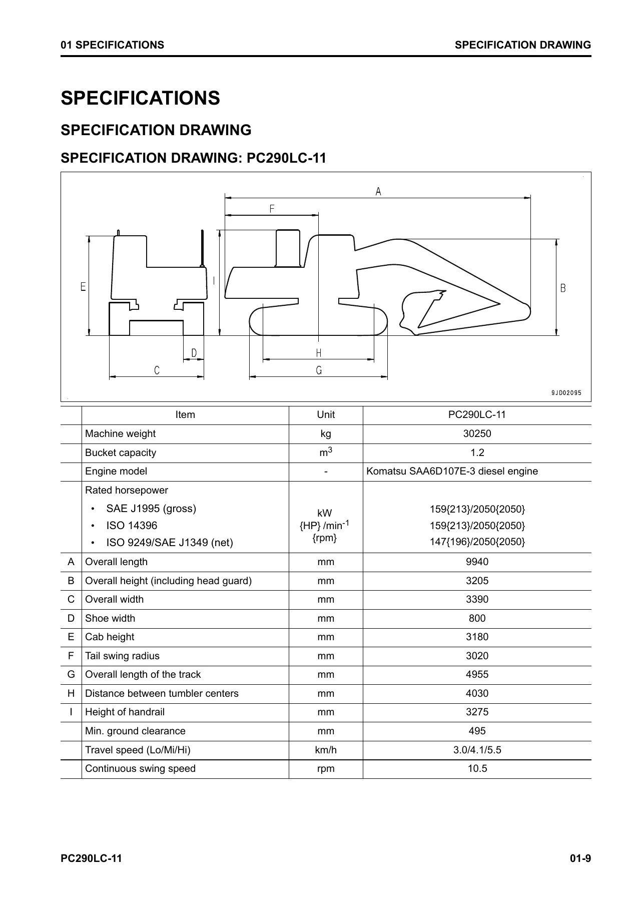
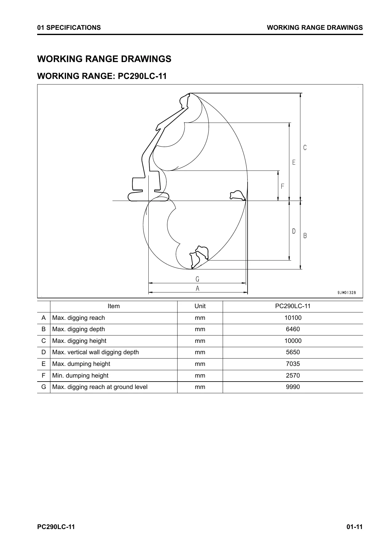
Provides the full specification drawing for the PC290LC-11, working range drawings, detailed specifications including engine, hydraulic system, undercarriage dimensions, working ranges, bucket capacity, machine weight, travel speed, swing speed, and the weight table for all major components. The table of fuel, coolant, and lubricants is also here.
10 Structure and Function
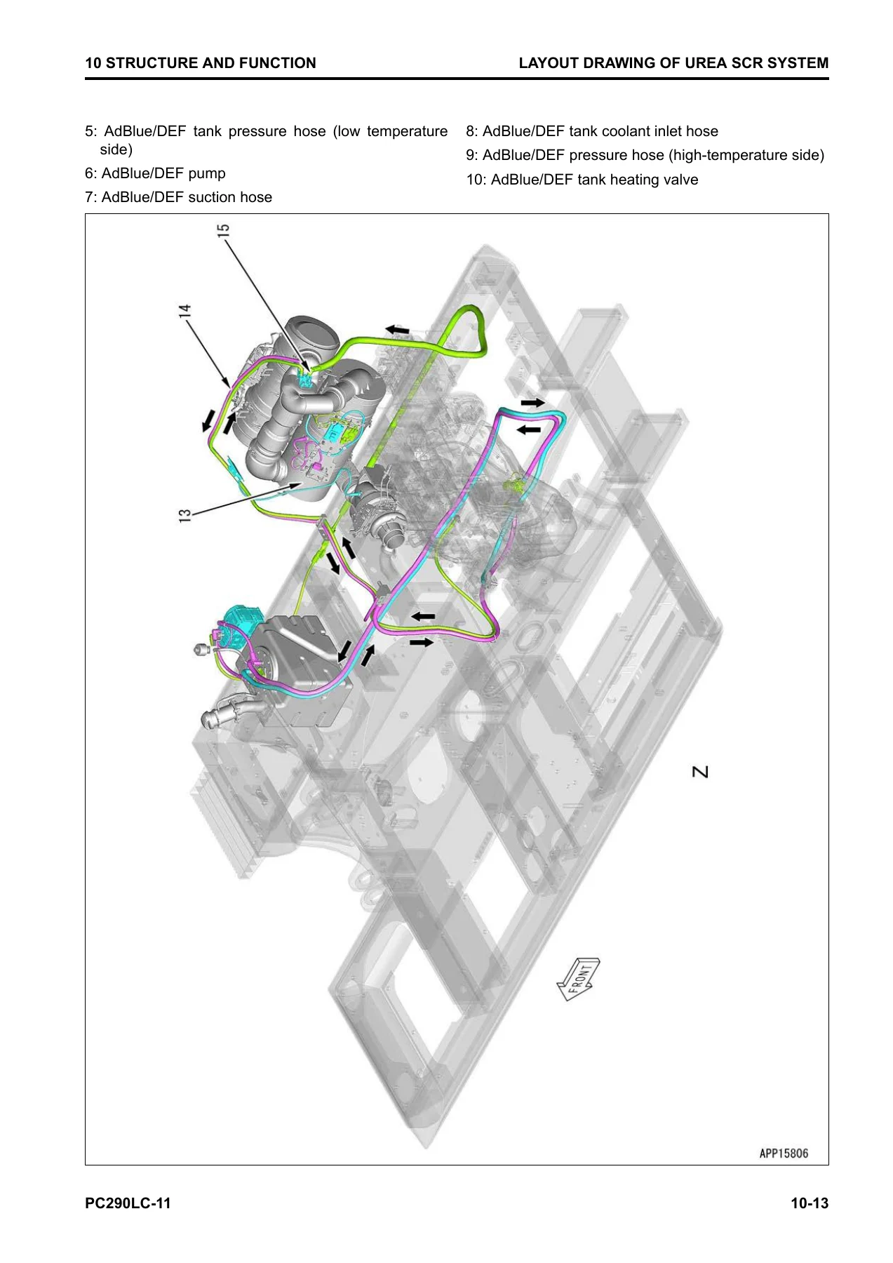
This is one of the largest sections, covering every major system on the machine. It includes the Urea SCR system with its layout, diagram, function, and component parts; the engine system with control, auto-deceleration, automatic warm-up, overheat prevention, and automatic idle stop; the cooling system; the control system including machine monitor, KomVision, and KOMTRAX; the hydraulic system covering the CLSS, engine and pump combined control, pump and valve control, and all component parts including main pump, LS valve, PC valve, EPC valves, and control valve; the work equipment system including valve control, one-touch power maximizing, PPC lock, and automatic lock; the swing system; the travel system; undercarriage and frame; work equipment structure and function; and cab and its attachments.
20 Standard Value Table
Contains the standard value tables for engine and machine, including performance standards, repair limits, and testing conditions. It includes the machine posture and procedure for measuring performance, and the electrical standard value table for controllers and sensors. This section is essential for determining whether a component is within specification or needs repair or replacement.
30 Testing and Adjusting
Lists all the tools required for testing and adjusting, with sketches of the special tools, and then provides detailed procedures for testing engine speed, boost pressure, exhaust gas color, valve clearance, compression pressure, blowby pressure, engine oil pressure, EGR valve and VGT oil pressure, fuel pressure, fuel discharge/return/leakage, fuel system air bleeding, fuel circuit leakage, cylinder cut-out mode, no-injection cranking, air conditioner compressor belt tension, ash in soot accumulation correction, and the full range of SCR-related function tests. It also covers power train tests, undercarriage tests, and the complete hydraulic system testing and adjusting procedures including work equipment, swing, travel circuit pressures, control circuit pressure, pump PC and LS control circuits, solenoid valve outlet pressure, PPC valve outlet pressure, attachment circuit oil pressure, pump swash plate sensor, hydraulic drift, oil leakage, and air bleeding. Cab and electrical system testing and adjusting are also included.
40 Troubleshooting
This is the largest section of the manual and the one most technicians will reach for first. It begins with general troubleshooting points, specific points for the Urea SCR system, and the sequence of events in troubleshooting. It then provides checks before troubleshooting, testing procedures, connector lists and layouts, connector contact identification, T-branch box and adapter tables, fuse location table, and precautions for cleaning and replacing KDPF. The failure code table is comprehensive, with each failure code described in detail including the failure, action of the controller, phenomenon on the machine, related information, and the step-by-step troubleshooting procedure with causes and remedies. The manual covers failure codes for the engine controller, pump controller, machine monitor, KOMTRAX, and KomVision systems. Separate troubleshooting sections are provided for the electrical system (E-mode) with symptoms like engine does not start, preheating issues, monitor display problems, gauge problems, and specific component failures; hydraulic and mechanical systems (H-mode) covering work equipment, swing, and travel problems; and engine (S-mode) covering starting, performance, and running issues.
50 Disassembly and Assembly
Provides the special tools list with sketches, coating materials list, and then the complete removal, installation, disassembly, and assembly procedures for the engine and cooling system, power train, undercarriage and frame, hydraulic system, work equipment, cab and its attachments, and electrical system. Each procedure includes the required tools, tightening torques, coating materials, and step-by-step instructions with illustrations.
60 Maintenance Standard
Contains the maintenance standards for each component, showing the criteria for judging whether parts should be replaced or can be reused. It covers the engine and cooling system, power train including swing circle, swing machinery, final drive, sprocket, and sprocket tooth profile, undercarriage and frame including track frame, idler cushion, track roller, carrier roller, track shoe, and triple shoe, hydraulic system including hydraulic tank, main pump, LS-EPC valve, PC-EPC valve, swing motor, travel motor, control valve, anti-drop valves, work equipment and swing PPC valve, travel PPC valve, attachment PPC valves, solenoid valve, attachment circuit selector valves, and center swivel joint, and work equipment including linkage, boom cylinder, arm cylinder, and bucket cylinder.
80 Appendix
Covers the air conditioner system in detail, including precautions for refrigerant, air conditioner components, specifications, configuration and function of the refrigeration cycle, component parts of the air conditioner system and unit, air conditioner controller, compressor, condenser, sensors, testing and troubleshooting procedures, circuit diagram and connector pin arrangement, installation locations of air conditioner parts, testing for air leakage, self-diagnosis function, and troubleshooting charts.
90 Circuit Diagrams
Contains the hydraulic circuit diagram and electrical circuit diagram for the PC290LC-11. The hydraulic circuit diagram is provided in two parts, and the electrical circuit diagram is provided in seven parts. Symbols used in the diagrams are also explained.
Why This Manual Matters
The PC290LC-11 is a Tier4 Final compliant machine with advanced systems including the Urea SCR system, KDPF, EGR, VGT, and the CLSS hydraulic system. Working on these systems without the correct procedures and specifications can lead to expensive damage, repeated failures, or non-compliance with emissions regulations. This manual gives you the exact values, torques, clearances, and diagnostic steps that Komatsu specifies for this machine.
Whether you are troubleshooting a failure code on the machine monitor, rebuilding a hydraulic pump, adjusting the valve clearance, or performing a manual stationary regeneration of the KDPF, the procedures in this shop manual tell you what to do, in what order, and with what values. The troubleshooting section alone, with its detailed failure code table and step-by-step diagnostic procedures, can save hours of guesswork.
IMAGES PREVIEW
Instant PDF Delivery – No Shipping, No Waiting
This Komatsu PC290LC-11 Shop Manual is delivered as an instant PDF download. There is no physical book to ship, no waiting for delivery, and no shipping cost. As soon as your payment is confirmed, you can download the manual and start using it. The PDF can be viewed on any device — laptop, tablet, or smartphone — and you can print the pages you need for the workshop. Whether you are in the field or in the shop, the manual is always available.
Stop relying on guesswork or incomplete information. Get the complete Komatsu PC290LC-11 Shop Manual with document number SEN06507-11 and have the correct procedures, specifications, and diagrams at your fingertips.
Reviews
There are no reviews yet.