
Komatsu PC300-3, PC300LC-3, PC360LC-3 Hydraulic Excavator Shop Manual – SEBM02070308 PDF Download
Original price was: $68.95.$45.95Current price is: $45.95.
Complete Komatsu shop manual (SEBM02070308) for the PC300-3, PC300LC-3 and PC360LC-3 hydraulic excavators. Engine S6D125-1, power train, undercarriage, hydraulic and electrical systems with testing, adjusting, disassembly, assembly and maintenance standards.
Description
The Komatsu PC300-3, PC300LC-3 and PC360LC-3 Hydraulic Excavator Shop Manual (publication SEBM02070308) is the complete service workshop reference for these three crawler excavator models, covering serial numbers PC300/LC-3 12001 and up, PC300LC-3 A13424 and up and PC360LC-3 10001 and up. Every chapter is written for the technician working on the machine: structure and function explanations, testing and adjusting procedures, disassembly and assembly sequences, and maintenance standards with the tolerances, clearances and torque values actually used in the workshop. The manual is supplied as a downloadable PDF so you can print the pages you need or keep the whole volume on a laptop or tablet in the service truck.
File Details
- Manual type: Shop Manual (service and repair)
- Brand: Komatsu
- Models covered: PC300-3, PC300LC-3, PC360LC-3
- Engine: S6D125-1
- Language: English
- Document number: SEBM02070308
- Publication date: July 1992
- Format: PDF
- Page count: 762 pages
Chapters Covered
- 01 General
- 10 Engine
- 20 Power Train
- 30 Undercarriage
- 60 Hydraulic System
- 80 Electric and Electronic System
01 General
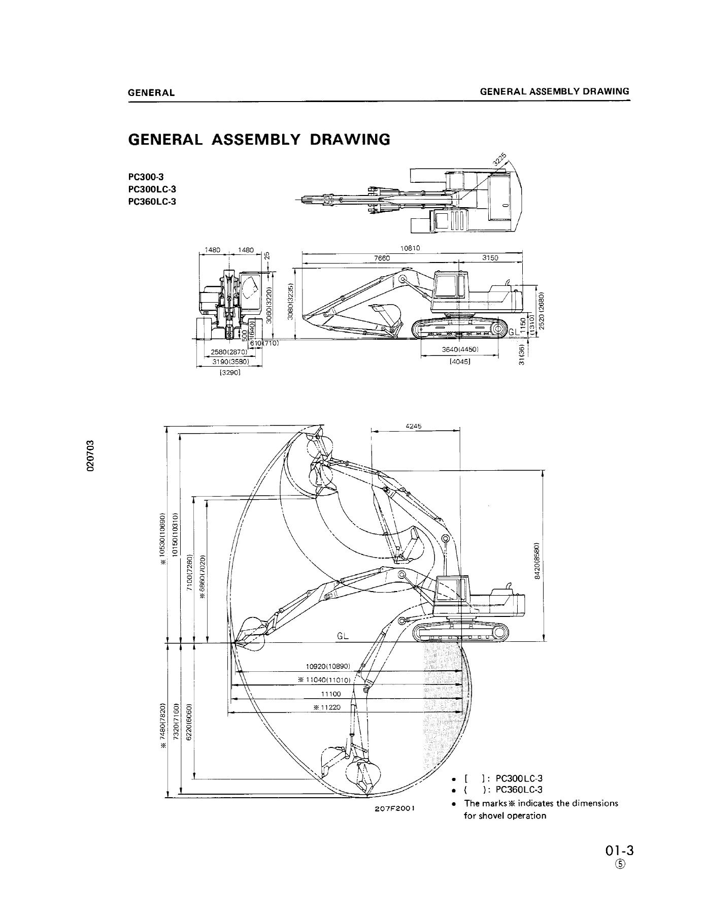
The opening chapter carries the safety notices that apply to every job in the book — parking and blocking the machine, relieving hydraulic and fuel pressure before opening circuits, sling and hoist practice, handling locking devices, and the standard tightening torques for bolts and nuts (including split flange bolts and flared nut connections). General also contains the model specification tables, the component weight lists used when planning a lift, the recommended fuel, coolant and lubricant chart with capacities, the electric wire colour and thickness code that decodes the electrical diagrams, and the manual’s own conventions for reading standard size, tolerance, repair limit and clearance limit.
10 Engine
Covers the S6D125-1 four-cycle, in-line, water-cooled, direct-injection turbocharged diesel in full. Structure and function explains the damper assembly — how the torsion spring and cone spring absorb crankshaft torsional vibration so it is not transmitted to the gear and piston pumps — along with the cooling package and the auto-deceleration system including the decelerator cylinder, solenoid valve, limit switch, oil pressure switch, shuttle valve and timer. Testing and adjusting provides the field numbers: valve clearance at 20°C (0.33 mm intake, 0.71 mm exhaust), compression pressure, exhaust gas colour, fuel injection timing, blow-by pressure, fan belt tension and the fuel control lever and deceleration cylinder adjustment procedures. Disassembly and assembly walks through the starting motor, alternator, engine oil cooler, fuel injection pump, water pump, nozzle holders, turbocharger, cylinder head, radiator core, hydraulic oil cooler, and the complete engine and main pump removal with the mount bolt torque (95 ± 10 kgm), plus the damper and the auto-deceleration cylinder.
20 Power Train
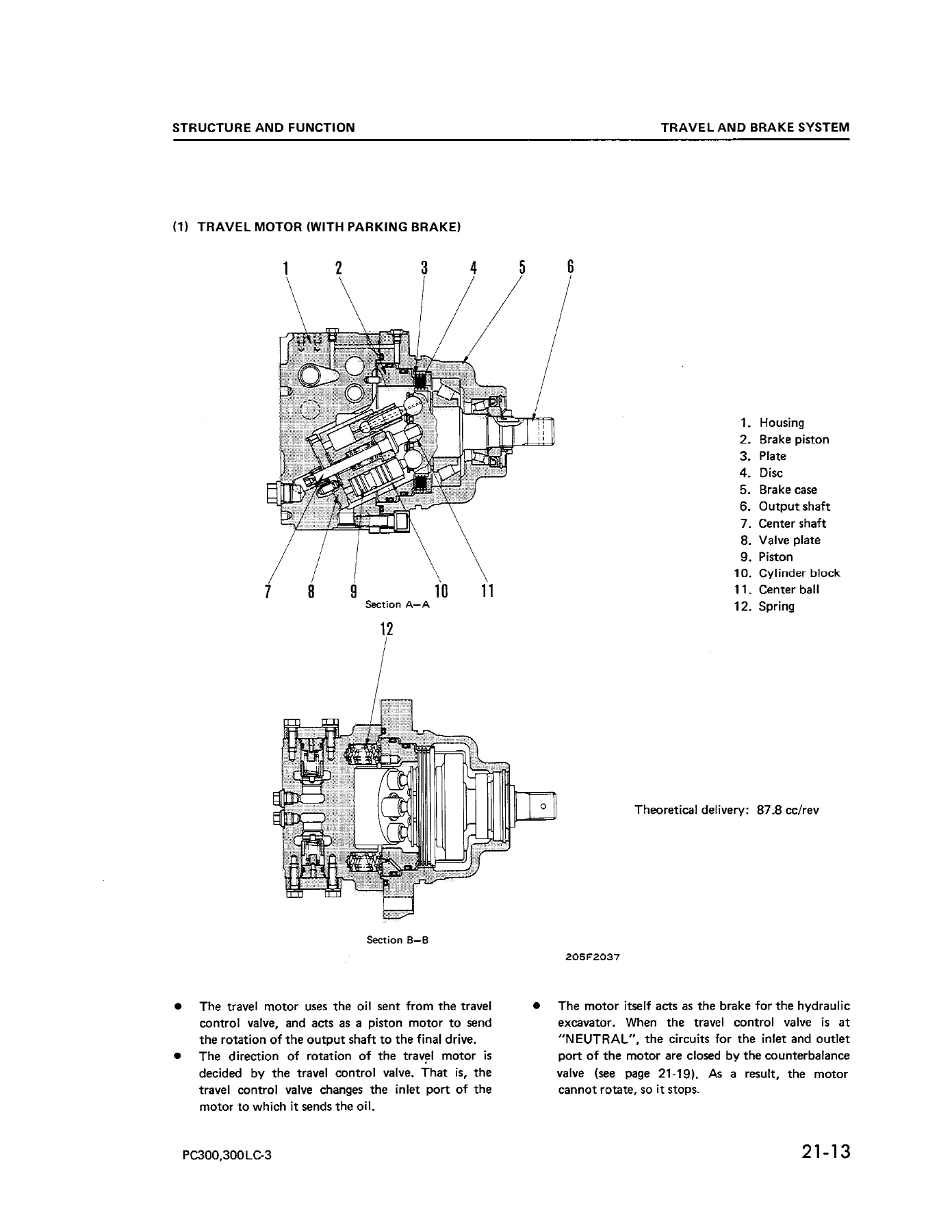
The travel and swing systems are covered in depth. Structure and function explains the travel control circuit, the straight-travel valve that keeps the machine tracking straight when a boom, arm, bucket or swing function is used while travelling, the center swivel joint, the axial-piston travel motor with its spring-applied hydraulically released parking brake, the counterbalance and safety valves inside the travel brake valve, the two-stage planetary final drive, and the swing circuit with swing priority valve, swing motor, safety valve and swing machinery. Disassembly and assembly covers the center swivel joint, travel motor, final drive, sprocket, swing motor (with and without swing mechanical brake) and swing circle. The maintenance standard chapter sets out the wear limits for the parts that come out of those units.
30 Undercarriage
Structure and function, disassembly and assembly, and maintenance standard for the track frame, recoil spring, idler, carrier and track rollers, track shoes, sprocket and the related hardware. The maintenance standard section gives the dimensional limits used to judge whether an undercarriage component can be reused or must be replaced.
60 Hydraulic System
The largest section of the manual. Structure and function describes the two variable-displacement piston main pumps and the gear-type charging pump, the control valve assemblies (4-spool and 5-spool), main relief settings, PPC valve operation, straight-travel control and the layout of the major implement, travel and swing circuits. Testing and adjusting gives the pressure and flow check procedures used to diagnose a weak, slow or drifting machine before parts are removed. Disassembly and assembly covers the pumps, control valves, cylinders and related assemblies, and maintenance standard lists the tolerances applied when inspecting the hydraulic components.
80 Electric and Electronic System
Structure and function for the electrical and electronic hardware — the wiring layout, connectors and the electronic control items — together with testing and adjusting procedures for the circuits that support the engine, travel, swing and auto-deceleration functions.
Serial Number Coverage
This shop manual applies to PC300-3 and PC300LC-3 from serial 12001 and up, PC300LC-3 from serial A13424 and up, and PC360LC-3 from serial 10001 and up. Confirm your machine’s serial plate against these ranges before using a procedure or a torque value — the manual is written around those machines and their S6D125-1 engine.
What You Can Do With It
This is the reference that lets you diagnose and repair a PC300-3, PC300LC-3 or PC360LC-3 without guessing. Use it to set valve clearance and injection timing, adjust the deceleration cylinder so the auto-deceleration system steps correctly between the No. 1 and No. 2 positions, reset fan belt tension, test main relief pressure, decide whether a travel motor or final drive is serviceable, rebuild a swing motor or center swivel joint, or replace a cylinder head and torque the head bolts in the correct order and stages. The testing and adjusting chapters work alongside the structure and function explanations so you understand how a circuit behaves before you open it, and the maintenance standard chapters give you the wear limits that separate a part worth reusing from one that has to be replaced.
IMAGES PREVIEW
Instant PDF Delivery
The full 762-page Komatsu shop manual is delivered as an instant download after payment — no shipping and no waiting. Read it on a phone, tablet, laptop or desktop, zoom into a sectional drawing or circuit schematic, and print only the pages you take to the machine. Whether you keep it on the shop computer or in the service truck, the PC300-3 / PC300LC-3 / PC360LC-3 shop manual SEBM02070308 stays available for every repair, every adjustment and every rebuild for as long as you own the machine.
Reviews
There are no reviews yet.