
Komatsu PC300-7 PC350-7 Excavator Shop Manual – SEBM025812 PDF
Original price was: $34.95.$21.95Current price is: $21.95.
Complete Komatsu Shop Manual (SEBM025812) covering PC300-7, PC300LC-7, PC350-7 and PC350LC-7 excavators with SAA6D114E engine. Full structure, testing and adjusting, disassembly/assembly, hydraulic and electrical troubleshooting in one PDF.
Description
Komatsu PC300-7 PC350-7 Shop Manual – SEBM025812
This is the complete Komatsu Shop Manual (document number SEBM025812) for the PC300-7, PC300LC-7, PC350-7 and PC350LC-7 hydraulic excavators. It is the service-workshop reference for these machines, covering structure and function, maintenance standards, testing and adjusting, disassembly and assembly, plus the hydraulic and electrical circuit diagrams needed for real diagnostic work.
The manual is intended for technicians who already understand the machine and need the actual factory procedures, clearances, torque values, pressure settings and disassembly sequences rather than generic advice. Everything in this PDF is written around the SAA6D114E engine and the PC300/PC350-7 hydraulic, swing, travel and electronic control systems.
File Details
- Manual type: Komatsu Shop Manual (Service / Repair Workshop Manual)
- Document number: SEBM025812
- Brand / Manufacturer: Komatsu
- Models covered: PC300-7, PC300LC-7, PC350-7, PC350LC-7
- Engine covered: SAA6D114E (SAA6D114E-2 in the standard value tables)
- Serial number ranges: PC300-7 / PC300LC-7: 40001 and up; PC350-7 / PC350LC-7: 20001 and up
- Language: English
- Format: PDF
- Page count: Approx. 775 pages
Note: this Komatsu PC300-7 PC350-7 Shop Manual covers the machine and chassis systems in detail. The engine itself is covered by the separate 114 Series Engine Shop Manual, as stated inside the front matter, so the engine chapter here focuses on how the engine is installed in the machine, its mountings, cooling package and controls rather than full internal engine overhaul.
Chapters Covered in this Komatsu PC300-7 PC350-7 Shop Manual
The Shop Manual is organised into the five standard Komatsu chapter groups, each further divided into component-level groups:
- 01 GENERAL
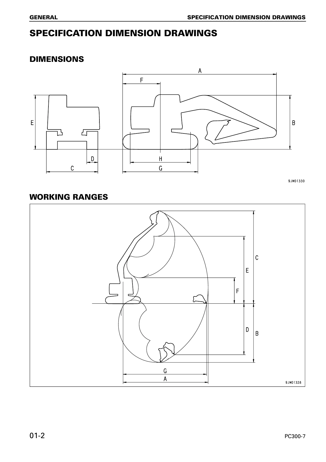
- Specification dimension drawings
- PC300-7 / PC300LC-7 specifications
- PC350-7 / PC350LC-7 specifications
- Weight tables for PC300-7 / PC300LC-7
- Weight tables for PC350-7 / PC350LC-7
- Fuel, coolant and lubricants
- 10 STRUCTURE, FUNCTION AND MAINTENANCE STANDARD
- Engine related parts, radiator, oil cooler, aftercooler
- Power train, final drive, sprocket
- Swing machinery, swing circle
- Track frame, recoil spring, idler, carrier roller, track roller, track shoe
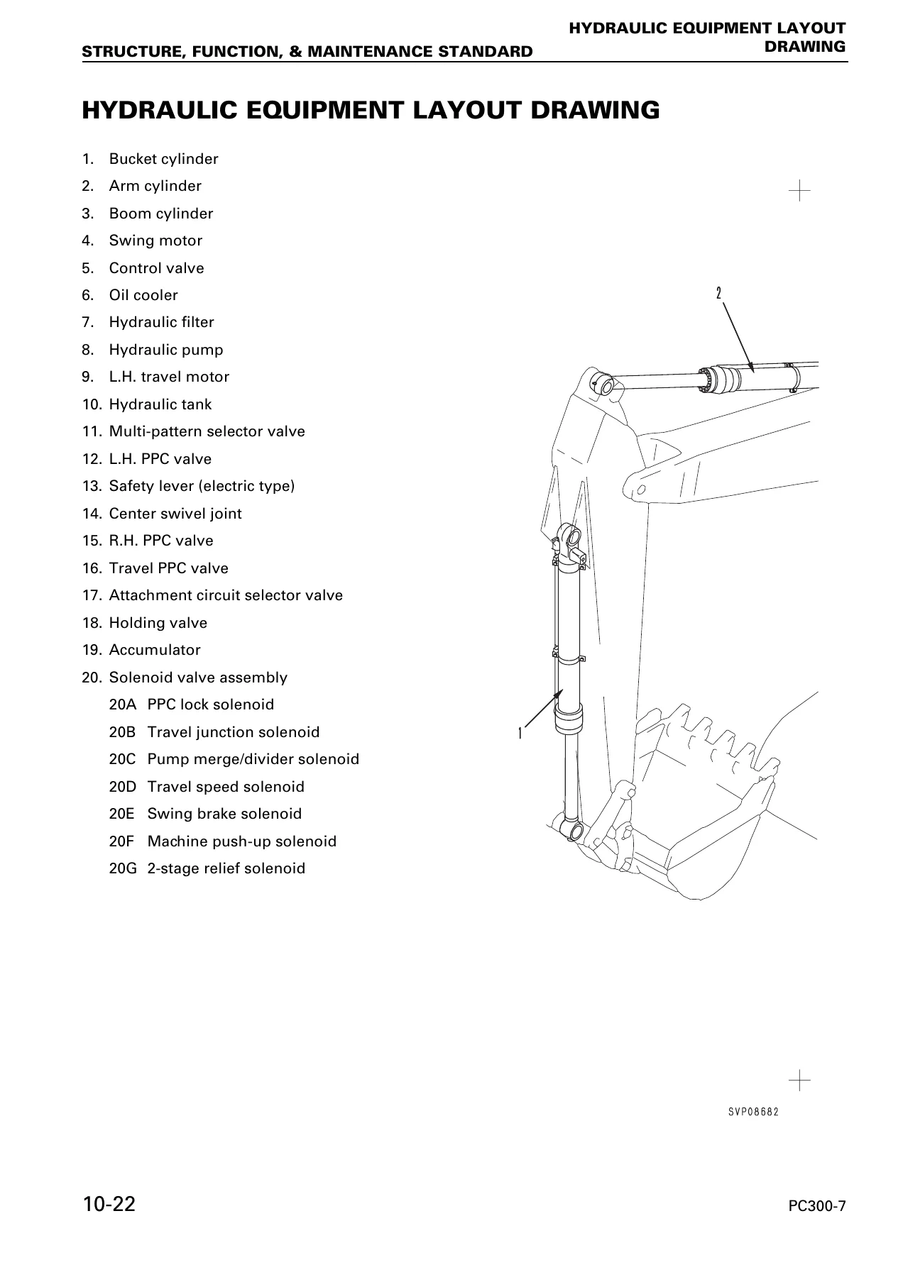
- Hydraulic equipment layout, hydraulic tank, hydraulic pump
- Variable volume valve, control valve, CLSS
- Self pressure reducing valve, swing motor, reverse prevention valve
- Center swivel joint, travel motor, travel junction valve, travel PPC shuttle valve
- Valve control, work equipment / swing PPC valve, travel PPC valve, service PPC valve
- Solenoid valve, PPC accumulator, return oil filter
- Boom hydraulic drift prevention valve, quick return valve, lift check valve, attachment circuit selector valve
- Hydraulic cylinder, work equipment, air conditioner
- Engine control, electronic control system
- Multi monitor system, 7-segment monitor system, sensors
- 20 TESTING AND ADJUSTING
- Standard value tables for engine and chassis related parts
- Tools for testing, adjusting and troubleshooting
- Inspection and adjustment of engine speed, valve clearance, fuel injection timing, engine oil pressure, engine speed sensor
- Measurement of air boost pressure, exhaust gas colour, compression pressure, blow-by pressure
- Swing circle bearing clearance, track shoe tension, sprocket wear
- Hydraulic oil pressure in the work equipment, swing and travel circuits
- Control circuit oil pressure, pump PC and LS control circuit oil pressure
- Solenoid valve and PPC valve output pressure measurement
- Adjustment of work equipment and swing PPC valve
- Release of remaining pressure in the hydraulic circuit, oil leakage measurement, air bleeding
- Diode inspection procedures
- Special functions of the multi-monitor panel and 7-segment monitor panel
- Preparations for troubleshooting the electrical system
- Troubleshooting: service codes, electrical system (E-mode), hydraulic and mechanical system (H-mode), engine (S-mode)
- Connector location charts and electrical circuit diagrams by system
- 30 DISASSEMBLY AND ASSEMBLY
- Starting motor assembly, fuel injection pump assembly
- Engine front seal, engine rear seal
- Cylinder head assembly, radiator assembly, hydraulic oil cooler assembly
- Engine and hydraulic pump assemblies
- Final drive assembly, swing motor and swing machinery assembly
- Carrier roller, track roller, idler, recoil spring, sprocket, track shoe assembly
- Swing circle, revolving frame, center swivel joint, hydraulic tank
- Control valve assembly, hydraulic pump assembly, oil seal in hydraulic pump input shaft
- Work equipment PPC valve, travel PPC valve, hydraulic cylinder assembly
- Work equipment assembly, air conditioner unit assembly
- Counterweight assembly, operator’s cab assembly, operator’s cab glass (stuck glass), front window assembly
- Monitor assembly, governor pump controller assembly
- 90 OTHERS
- Hydraulic circuit diagram
- Electrical circuit diagram (4 sheets), split by serial number range
What This Manual Gives a Technician
This is not a lightweight owner’s handbook. It is the working reference that service technicians open when they need to actually repair, adjust or diagnose a PC300-7 or PC350-7. Each section pairs structure and function explanations with the matching maintenance standards, so a rebuild, adjustment or pressure test is done against the values Komatsu specifies for these machines rather than guesses.
Structure, Function and Maintenance Standard is the backbone. It documents each major assembly – final drive, swing machinery, swing circle, track frame, idler, carrier roller, track roller, travel motor, swing motor, control valve, hydraulic pump, PPC valves, monitor systems – with the component breakdown and the wear limits, clearances and rebuild criteria needed to judge whether a part is still serviceable. For example, the final drive chapter gives the reduction ratio, the backlash limits for No. 1 and No. 2 planetary gear sets, sprocket tooth wear limits and rebuild dimensions. The swing machinery chapter gives the backlash values between sun gears, planetary gears and ring gears, plus the clearance limits between the plate and coupling. Idler, carrier roller and track roller sections carry the outside diameter, tread thickness and bushing clearance limits that decide rebuild or replace.
Testing and Adjusting is where the diagnostic side of the book lives. It opens with standard value tables for engine related parts and chassis related parts – idle speeds, rated speed, boost pressure, compression pressure, blow-by pressure, oil pressure, fan belt deflection, hydraulic pressures, spool strokes, control lever travels and operating forces, swing and travel timings, hydraulic drift limits, oil leakage amounts. From there it walks through the actual procedures: how to measure engine speed, boost pressure, exhaust gas colour, compression and blow-by pressure, valve clearance, fuel injection timing, engine oil pressure, swing circle bearing clearance, track shoe tension and sprocket wear. The hydraulic side is fully covered, including unload pressure, main relief and 2-stage relief settings, boom LOWER safety valve settings, swing relief pressure, travel circuit relief pressure, control circuit pressure, pump PC and LS control pressures, and the LS-EPC and PC-EPC solenoid outputs. PPC valve output pressures and the mechanical adjustment of the work equipment and swing PPC valve are also covered.
Disassembly and Assembly gives the actual removal, installation, disassembly and assembly procedures for each major component, with the special tools listed and their part numbers, tightening torques, coating agents, gasket sealants and greasing points called out at every step. The final drive, swing motor and swing machinery, control valve, hydraulic pump, hydraulic cylinders, center swivel joint and track assemblies are all broken down at component level with the assembly sequences and press-fit forces shown.
Troubleshooting is organised the way a working tech actually thinks. It starts with a failure-looking phenomenon index – engine will not start, engine stops in operation, machine does not swing, travel is slow, work equipment drifts, monitor has no display – and each entry points to a specific troubleshooting code. Service codes for the electrical system, failure codes for the mechanical system, E-mode electrical troubleshooting, H-mode hydraulic and mechanical troubleshooting, and S-mode engine troubleshooting are all included, backed by connector location charts and system-by-system electrical circuit diagrams.
Jobs and Repairs This Komatsu PC300-7 PC350-7 Shop Manual Supports
With this manual on hand, a technician can carry out the major service and repair work on these machines correctly:
- Full hydraulic system diagnosis and pressure adjustment, including main relief, 2-stage relief, LS valve, PC valve, servo piston and pump control checks
- Control valve spool, pressure compensation valve, LS shuttle valve, regeneration valve and unload valve service
- Swing motor, swing machinery and swing circle inspection, disassembly, rebuild and clearance setup
- Travel motor, final drive, counterbalance valve, safety valve and speed shift diagnosis and rebuild
- Track frame, idler, carrier roller, track roller, recoil spring and track shoe service with wear limits
- Centre swivel joint disassembly and seal replacement
- Work equipment cylinder disassembly, piston, packing, bushing and rod seal replacement
- Electronic control system diagnostics using service codes, failure codes and monitor panel special functions
- Engine related in-machine service – fuel injection pump, cylinder head, engine front and rear seals, starting motor
- Cooling package service – radiator, oil cooler and aftercooler removal and installation
- Operator’s cab, stuck glass, front window and air conditioner unit service
Why Correct Specifications and Procedures Matter on a PC300/PC350-7
These are large hydraulic machines running high system pressures and precisely matched closed-centre load sensing (CLSS) hydraulics. Small mistakes in relief pressure, LS differential pressure, pump swash plate timing or spool clearance do not simply make the machine slow – they cause overheating, hammering, drift, cylinder scoring or premature pump and motor failure. Using the pressure values, clearances, torques and rebuild limits that Komatsu specifies for the PC300-7, PC300LC-7, PC350-7 and PC350LC-7 is the difference between a repair that holds and one that comes back.
The electronic side is just as important. The governor and pump controller on these machines manages engine/pump composite control, power max, auto-deceleration, auto warm-up, travel speed switching, swing brake logic and cut-off functions. Diagnosing these without the service code list, connector pin data and circuit diagrams wastes hours. This manual gives the technician all of that for both the multi-monitor and 7-segment monitor specifications, including the serial-number split so the right diagram is used for the right machine.
IMAGES PREVIEW
Instant PDF Delivery
The Komatsu PC300-7 PC350-7 Shop Manual (SEBM025812) is delivered as a downloadable PDF immediately after purchase. There is no shipping, no waiting for a physical book, and no risk of a manual arriving damaged. The PDF can be opened on a workshop laptop, a tablet at the machine, or a phone in the field, and pages can be printed whenever a paper copy is more practical for a specific repair. Once purchased, the file is yours to keep for reference during every future service on the machine.
Reviews
There are no reviews yet.