Trusted Business
Verified & Licensed
Virus Free Files
100% Safe Downloads
Secure Payment
SSL Protected
Instant Delivery
Available Immediately
Sale!


KOMATSU PC3000-1 HYDRAULIC MINING SHOVEL SERVICE REPAIR MANUAL (SN:PC3000-1 6171) KOMATSU PC3000-1 – PDF DOWNLOAD
Original price was: $73.95.$27.95Current price is: $27.95.
- KOMATSU PC3000-1 HYDRAULIC MINING SHOVEL SERVICE REPAIR MANUAL
- SERIAL NUMBER:PC3000-1 6171
- PUBLICATION NUMBER:SMPC30006171
Instant PDF Download
Available immediately
Save to Your Device
Download & keep forever
Antivirus Scanned
100% virus-free
Trusted Worldwide
175,000+ customers
Description
KOMATSU PC3000-1 HYDRAULIC MINING SHOVEL SERVICE REPAIR MANUAL (SN:PC3000-1 6171) KOMATSU PC3000-1
KOMATSU PC3000-1 HYDRAULIC MINING SHOVEL SERVICE REPAIR MANUAL (SN:PC3000-1 6171) KOMATSU PC3000-1 – PDF DOWNLOAD:
IMAGE PREVIEW:
DESCRIPTION:
KOMATSU PC3000-1 HYDRAULIC MINING SHOVEL SERVICE REPAIR MANUAL (SN:PC3000-1 6171) KOMATSU PC3000-1
- In this part we describe all functions; testing and adjustment procedures.Of course for better understanding of the systems the hydraulic and electric circuit diagram is very helpful and a must for fault finding.
- Whenever it is possible for the description the circuit diagram numbers / codes are used.
- One who is not able to understand the circuit diagram or is not so familiar with the used symbols should study the hints for the circuit diagrams Section 10 and 11.
Following abbreviations are used:
PDG = Pump-Distributor-Gear
LBA = Loader-Bucket-Attachment
BHA = Back-Hoe-Attachment
NIRV = Main-Relief Valve (Primary valve)
SRV = Service-line-Relief Valve (Secondary valve)
ACV = Anti-Cavitation Valve
EPM = Electronic-Power Module
ESR = Electronic-Signal Rectifier
ELL = Electronic-Load Limiter
EFM = Electronic-Fuel Measurement
DRE = Druck-Reduzierventil-Elektrisch (Pressure Reducing Valve Electrical)
EGR = Elektronische-Grenzlast-Regelung (Electronic Load Limit Regulation)
EBL = Electronic Bucket Leveling
ETM = Electronic Text and Monitoring System
CLS = Central Lubrication System
STC = Slew ring Teeth Central Lubrication System
PTO = Power Take Off
RPM = Revolutions Per Minute
All adjustments and pressure settings for the hydraulic circuits must be
carried out at normal operating temperature
For service intervals, oil levels and filling capacities see the “Service Literature”, because this literature is always made for the specific machine
TABLE OF CONTENTS:
KOMATSU PC3000-1 HYDRAULIC MINING SHOVEL SERVICE REPAIR MANUAL (SN:PC3000-1 6171) KOMATSU PC3000-1
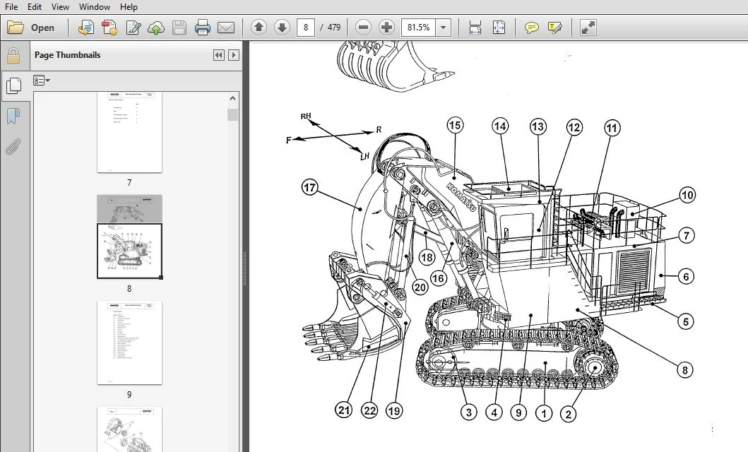
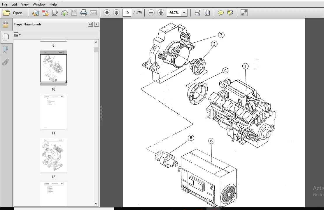
Main Menu.....................................................................  0
Cover.........................................................................  1
Introduction..................................................................  2
Symbols.......................................................................  3
Foreword......................................................................  4
Table of Contents.............................................................  6
Section 1 - Main Assembly Groups..............................................  7
	Table of Contents, Section 1..............................................  7
		General Layout........................................................  9
		Drive................................................................. 11
		Control Blocks, Slew Gear............................................. 13
		Undercarriage, Travel Drive........................................... 15
		Driver's Cab.......................................................... 17
Section 2 - Drive............................................................. 19
	Table of Contents, Section 2.............................................. 19
		Prime Drive Assembly.................................................. 21
		Engine Mounts......................................................... 23
		Fan Drive and Cooler Assy............................................. 25
		Coupling.............................................................. 27
		Air Filter............................................................ 29
		Pump Distributor Gear................................................. 31
		Pump Spline - Lubrication............................................. 33
		PTO - Gear Ludrication................................................ 35
Section 3 - Hydraulic Oil Tank................................................ 41
	Table of Contents, Section 3.............................................. 41
		Main Oil Tank......................................................... 43
		Return and Leak Oil Filter............................................ 45
		Breather Filter....................................................... 47
		Location of Pressure Switches and Sensors............................. 49
Section 4 - Hydraulic Oil Cooling............................................. 51
	Table of Contents, Section 4.............................................. 51
		General............................................................... 53
		Hydraulic Oil Cooling Circuit......................................... 55
		Measuring / Setting the Back Pressure Valve........................... 57
		Fan Drive............................................................. 61
		Axial Piston Pump..................................................... 65
		Measuring and Setting of the Fan Speed................................ 67
		Function Check for RPM-Control........................................ 71
Section 5 - Controlling....................................................... 73
	Table of Contents, Section 5.............................................. 73
		Pilot Pressure Supplu................................................. 75
			General........................................................... 75
			Function.......................................................... 77
		Checks and Adjustment of Pilot Pressure............................... 79
		Measuring and Adjustment of Control Pressure.......................... 81
			Checking of Accumulator Function.................................. 81
			Checking of Accumulator Pre-charge Pressure....................... 81
		Travel Parking Brake.................................................. 83
		Function Check of Travel Parking Brake................................ 85
		Slew Parking (House) Brake............................................ 87
Section 6 - Components........................................................ 89
	Table of Content.......................................................... 89
		Main Control Blocks and High Pressure Filter (Bull-Clam Attachment.... 91
		Main Control Blocks and High Pressure Filter (Back Hoe Attachment..... 93
		Distributor Manifold (Bull-Clam Attachment)........................... 95
		Distributor Manifold (Back Hoe Attachment............................. 97
		Restrictor Block with Pressure Valve.................................. 99
		Restrictor Block......................................................101
		Anti Cavitation Valve Block...........................................103
		Proportional Solenoid Valve...........................................105
		Pressure Filter.......................................................107
		Control Blocks........................................................109
			Control Blocks and Valves.........................................111
			Valve at the Control Block........................................115
			Load Holding Valve................................................117
		Travel Brake Valve....................................................119
		Pressure Reducing Valve...............................................121
		Directional Control Valve (Solenoid Valve)............................123
		Hydraulic Cylinder....................................................125
		Auxiliary Pumps, Fan Drive............................................127
		Auxiliary Gear Pumps..................................................129
		Slew Ring.............................................................131
Section 7 - Main Hydraulic Pumps and Pump Regulation..........................133
	Table of Content..........................................................133
		Main Hydraulic Pump A7V / HD D........................................135
		SL-Bearing............................................................139
		Function of the Pump Governor.........................................141
		Pump Bearing Lubrication..............................................147
		Pump Governor Adjustments.............................................151
		Pump Regulation, General..............................................161
		Determination of Peak Point (Engine Performance Test).................167
		Hydraulic Regulation Adjustment, Stop Gap Operation...................169
		Detailed Explanation for Electronic Pump Regulation...................171
		Adjustments / Checks for Electronic Pump Regulation...................173
		Adjusting the RPM Sensor (MPU)........................................175
		Adjustments at the ELL - Module, Normal Fine Tuning...................177
		Checks / Function Test / Fault Finding at JOBSITE.....................181
		EPM - Module, Function and Test.......................................183
		ERM - Module, Function and Test.......................................185
		ELL - Module, Function and Test.......................................189
		Amplifier Module, Function and Test...................................193
		Simplified Trouble Shooting of Electronic Regulation..................195
Section 8 - Operating Hydraulic...............................................199
	Table of Content..........................................................199
		Hydraulic for Attachment Cylinder.....................................201
		Adjustments for Attachment Cylinder Hydraulic.........................205
		Slew Circuit, General.................................................223
		Slew Motor............................................................227
		Slew Gear and House Brake.............................................231
		Slew Brake Valve......................................................235
		Slew Function.........................................................240
		Checks and Adjustments................................................251
		Travel Citcuit........................................................259
		Rotary Distributor....................................................263
		Travel Motor (Axial Piston Motor A2FM)................................265
		Travel Gear and House Brake...........................................269
			Travel Gear.......................................................269
			Travel Gear House Brake...........................................271
		Travel, Function......................................................273
		Anti-Cavitation Circuit...............................................277
		Adjustments / Checks..................................................279
Section 9 - Hydraulic Tank Tension System.....................................285
	Table of Content..........................................................285
		Hydraulic Track Tension System........................................287
			Function..........................................................289
			Pressure Increasing Valve.........................................293
			Pressure Relief Valve, Direct Operated............................295
			Adjustments / Pressure Checks.....................................297
Section 10 - Hints for the Hydraulic Circuit Diagram..........................305
	Table of Content..........................................................305
		Hints for Reading Circuit Diagrams....................................309
		Legend of the Hydraulic Circuit Diagram...............................310
		Pressure Check Points.................................................314
		How to Read the Circuit Diagram.......................................316
	Hydraulic Diagram (1/3)...................................................317
	Hydraulic Diagram (2/3)...................................................318
	Hydraulic Diagram (3/3)...................................................319
Section 11 - Hints for the Electric Circuit Diagram...........................321
	Table of Content..........................................................321
		Markings of Electrical Components in Circuit Diagrams.................323
		Symbols...............................................................325
		KGM Circuit Diagrams..................................................329
			General Information...............................................329
			Explanation of the Drawing Concept................................331
			Terminal Plans....................................................333
			Location of Main Terminal Boxes and Important Components..........335
			Reading a Circuit Diagram.........................................337
		Adjustments...........................................................341
		Component List / Function.............................................342
	Electrical Diagrams.......................................................348
		Electrical Diagrams - 897 818 40 (1/49)...............................348
		Electrical Diagrams - 897 818 40 (2/49)...............................349
		Electrical Diagrams - 897 818 40 (3/49)...............................350
		Electrical Diagrams - 897 818 40 (4/49)...............................351
		Electrical Diagrams - 897 818 40 (5/49)...............................352
		Electrical Diagrams - 897 818 40 (6/49)...............................353
		Electrical Diagrams - 897 818 40 (7/49)...............................354
		Electrical Diagrams - 897 818 40 (8/49)...............................355
		Electrical Diagrams - 897 818 40 (9/49)...............................356
		Electrical Diagrams - 897 818 40 (10/49)..............................357
		Electrical Diagrams - 897 818 40 (11/49)..............................358
		Electrical Diagrams - 897 818 40 (12/49)..............................359
		Electrical Diagrams - 897 818 40 (13/49)..............................360
		Electrical Diagrams - 897 818 40 (14/49)..............................361
		Electrical Diagrams - 897 818 40 (15/49)..............................362
		Electrical Diagrams - 897 818 40 (16/49)..............................363
		Electrical Diagrams - 897 818 40 (17/49)..............................364
		Electrical Diagrams - 897 818 40 (18/49)..............................365
		Electrical Diagrams - 897 818 40 (19/49)..............................366
		Electrical Diagrams - 897 818 40 (20/49)..............................367
		Electrical Diagrams - 897 818 40 (21/49)..............................368
		Electrical Diagrams - 897 818 40 (22/49)..............................369
		Electrical Diagrams - 897 818 40 (23/49)..............................370
		Electrical Diagrams - 897 818 40 (24/49)..............................371
		Electrical Diagrams - 897 818 40 (25/49)..............................372
		Electrical Diagrams - 897 818 40 (26/49)..............................373
		Electrical Diagrams - 897 818 40 (27/49)..............................374
		Electrical Diagrams - 897 818 40 (28/49)..............................375
		Electrical Diagrams - 897 818 40 (29/49)..............................376
		Electrical Diagrams - 897 818 40 (30/49)..............................377
		Electrical Diagrams - 897 818 40 (31/49)..............................378
		Electrical Diagrams - 897 818 40 (32/49)..............................379
		Electrical Diagrams - 897 818 40 (33/49)..............................380
		Electrical Diagrams - 897 818 40 (34/49)..............................381
		Electrical Diagrams - 897 818 40 (35/49)..............................382
		Electrical Diagrams - 897 818 40 (36/49)..............................383
		Electrical Diagrams - 897 818 40 (37/49)..............................384
		Electrical Diagrams - 897 818 40 (38/49)..............................385
		Electrical Diagrams - 897 818 40 (39/49)..............................386
		Electrical Diagrams - 897 818 40 (40/49)..............................387
		Electrical Diagrams - 897 818 40 (41/49)..............................388
		Electrical Diagrams - 897 818 40 (42/49)..............................389
		Electrical Diagrams - 897 818 40 (43/49)..............................390
		Electrical Diagrams - 897 818 40 (44/49)..............................391
		Electrical Diagrams - 897 818 40 (45/49)..............................392
		Electrical Diagrams - 897 818 40 (46/49)..............................393
		Electrical Diagrams - 897 818 40 (47/49)..............................394
		Electrical Diagrams - 897 818 40 (48/49)..............................395
		Electrical Diagrams - 897 818 40 (49/49)..............................396
Section 12 - Electronic Text Monitoring System................................398
	Table of Content..........................................................398
		Introduction..........................................................399
		Function..............................................................402
		Lay Out of Dash Board.................................................408
		Text Monitoring System................................................416
		Frequency / Voltage Converter (EFD-Module)............................476
PLEASE NOTE:
⦁ This is not a physical manual but a digital manual – meaning no physical copy will be couriered to you. The manual can be yours in the next 2 mins as once you make the payment, you will be directed to the download page IMMEDIATELY.
⦁ This is the same manual used by the dealers inorder to diagnose your vehicle of its faults.
⦁ Require some other service manual or have any queries: please WRITE to us at [email protected]


Kellen Kingston –
Kabir –