
Komatsu PC350LC-8 & PC350NLC-8 Hydraulic Excavator Operation and Maintenance Manual UEAM007002 – PDF Download
Original price was: $49.95.$34.95Current price is: $34.95.
Complete 502-page Komatsu operation and maintenance manual for PC350LC-8, PC350NLC-8, PC350LCD-8 and PC350NLCD-8 hydraulic excavators (serial K50001 and up). Covers safety, operation, periodic maintenance, specifications, attachments and the high reach demolition equipment supplement. Instant PDF download.
Description
Komatsu PC350LC-8 and PC350NLC-8 Hydraulic Excavator Operation and Maintenance Manual – Form UEAM007002
This is the full Komatsu operation and maintenance manual for the PC350LC-8, PC350NLC-8, PC350LCD-8 and PC350NLCD-8 hydraulic excavators, covering machine serial numbers K50001 and up. Published under form number UEAM007002, it runs to 502 pages of English text and combines the operator’s handbook with the complete periodic maintenance programme in a single reference. Everything from pre-start checks and warm-up routines through to torque values, hydraulic circuit air bleeding, track tension adjustment and the high reach demolition attachment procedures is inside this one PDF.
File Details
- Manual type: Operation and Maintenance Manual
- Brand: Komatsu
- Models covered: PC350LC-8, PC350NLC-8, PC350LCD-8, PC350NLCD-8
- Serial number range: K50001 and up (all four models)
- Language: English
- Page count: 502
- File format: PDF
- Document number: UEAM007002
- Publication date: July 2007 (07-07)
- Manufacturer listed: Komatsu UK Ltd, Birtley, Co. Durham, United Kingdom
Chapters Covered
- Safety
- Operation
- Maintenance
- Specifications
- Attachments and Options
- High Reach Demolition Manual
Each of these top-level chapters contains the sub-sections listed below. Front-matter items such as the Foreword, Index and Colophon are not technical chapters and are not described here.
Safety
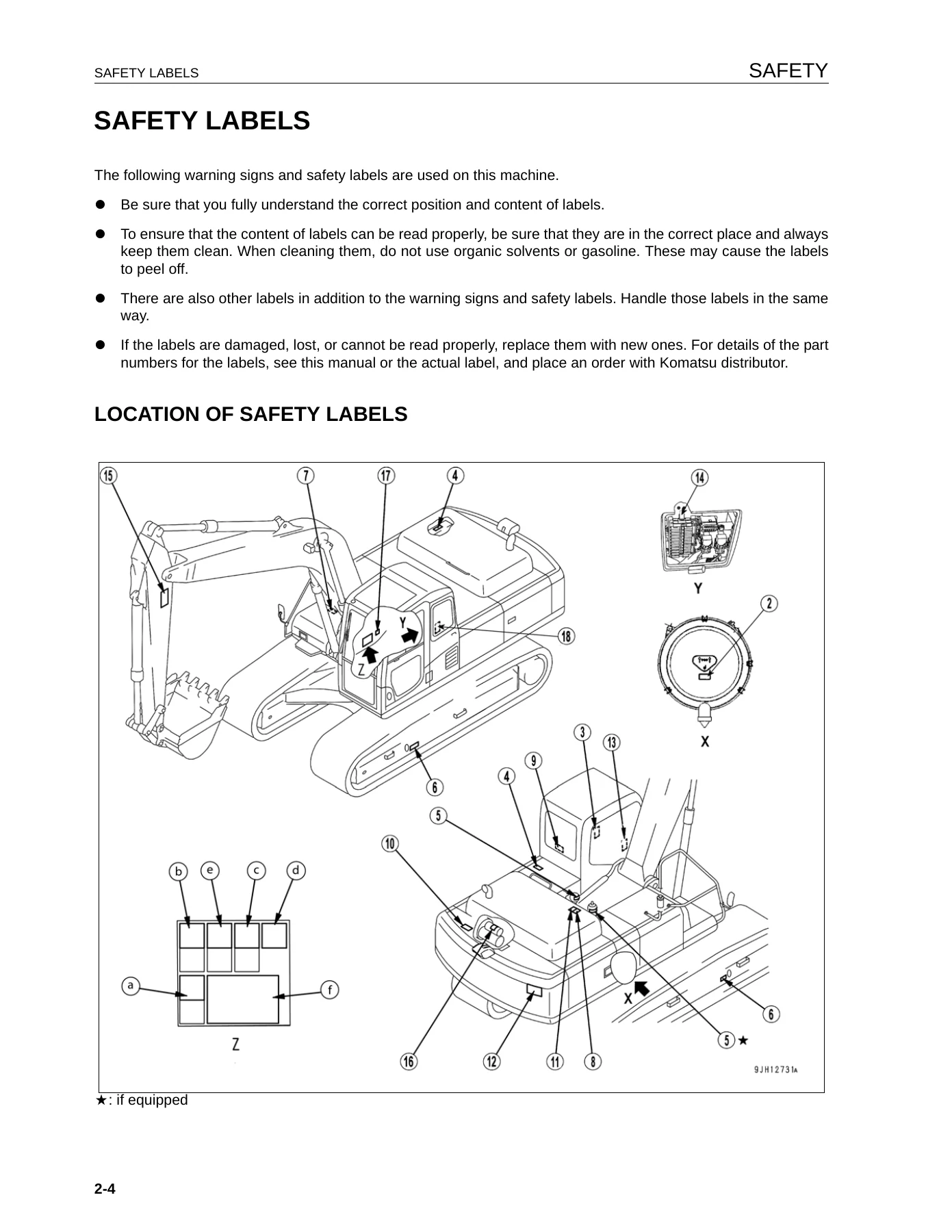
Signal-word conventions (DANGER, WARNING, CAUTION, NOTICE, REMARKS), pictogram safety labels and their exact positions on the machine, noise emission values (LpA 71 dB at the operator station, LWA 105 dB guaranteed per directive 2000/14/EC), vibration levels to ISO 7096, and a guide to reducing vibration through correct equipment, terrain, seat adjustment and operating technique. Separate sub-sections cover starting the engine, day-to-day operation, transportation, battery handling, towing, lifting with the bucket, and safety maintenance information such as warning tags, working under the machine, accumulator and gas spring handling, high-pressure oil, high fuel pressure, high voltage and periodic replacement of safety-critical parts.
Operation
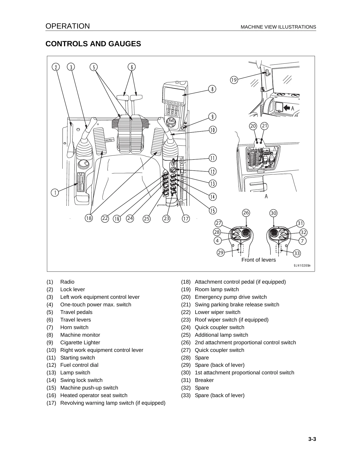
The largest chapter in the manual. It opens with an overall machine view keyed to bucket, bucket cylinder, arm, arm cylinder, boom, boom cylinder, sprocket, track frame, track shoe and idler, then walks through the complete cab control set: starting switch, fuel control dial, lamp switch, swing lock switch, machine push-up switch, wipers, heated seat, one-touch power max, cigarette lighter, room lamp, emergency pump drive, swing parking brake release, quick coupler, first and second attachment proportional control switches, breaker switch and additional lamp. The machine monitor system is fully explained – emergency monitors, caution monitors, basic check monitors, meter display, pilot lamps, working mode selector, travel speed selector, auto-deceleration, function switches F1-F6, maintenance interval screen and user mode. Subsequent sub-sections cover control levers and pedals, sun roof, windshield, emergency escape hammer, door lock, cap with lock, drink box, magazine box, ashtray, air conditioner controls, radio and antenna, 24 V and 12 V auxiliary power, fuse capacities and circuit names, fusible links, engine and pump controllers, toolbox, grease pump holder, fire extinguisher, refuelling pump and the accumulator. Operating content includes walk-around checks, checks before starting, seat and seat belt adjustment, engine starting (including cold-weather preheat and turbo-protect), engine and hydraulic warm-up, stopping, machine travel, steering, swing, work equipment controls, working modes (P, E, L, B, ATT), prohibited operations, slope travel, escape from mud, recommended applications, bucket replacement and inversion, parking, locking, transportation with loading and unloading, cold-weather operation, long-term storage and a full troubleshooting and actions chapter covering running out of fuel, discharged battery, booster-cable starting, electrical faults, chassis faults, engine faults and electronic control system error codes (E02, E03, E10, E11, E14, E15, E0E).
Maintenance
The periodic maintenance programme. It opens with maintenance information, service-meter reading habits, Komatsu genuine parts and lubricants, welding precautions, dust-site handling, hydraulic hose installation rules and post-maintenance checks. It then covers handling oil, fuel, coolant and grease, KOWA (Komatsu Oil Wear Analysis) sampling, storage of oils and filters, the lubrication chart decal, electrical-system maintenance, a wear-parts list with part numbers and change intervals, recommended fuel/coolant/lubricant charts with ambient temperature ranges and refill capacities, tightening torque specifications for metric and UNF hardware, and the safety-critical parts list. The schedule itself is laid out as Initial 1000 hours, When required, Checks before starting, Every 50, 250, 500, 1000, 2000, 4000, 5000 and 8000 hours. Maintenance procedures include air cleaner element service, cooling-system cleaning, track shoe bolt tightening and track tension adjustment, bucket tooth, side cutter and shroud replacement, bucket clearance adjustment, washer fluid top-up, air conditioner service, washable floor cleaning, hydraulic system air bleeding, greasing, swing circle and swing pinion lubrication, battery electrolyte checks, air conditioner compressor belt tension, swing machinery and final drive oil checks, fuel pre-filter and main filter cartridge replacement, engine oil and filter change, radiator, oil cooler, aftercooler and condenser fin cleaning, fresh/recirc air filter cleaning, hydraulic tank breather and additional breather element replacement, hydraulic oil filter element replacement, swing machinery oil change, damper case oil level, exhaust clamp checks, fan and alternator belt checks, breaker accumulator nitrogen pressure checks, corrosion resistor cartridge replacement, final drive oil change, hydraulic tank strainer cleaning, control-circuit accumulator function check, and a dedicated hydraulic-breaker maintenance interval schedule.
Specifications
Machine specifications for the PC350LC-8 and PC350NLC-8, including operating weight (34,800 kg and 34,310 kg), bucket capacity (1.4 m3), engine name (Komatsu SAA6D114E-3 diesel), engine output (184 kW / 247 HP at 1,900 rpm), overall length (11,140 mm), overall height (3,285 mm), overall width (3,290 mm / 2,990 mm), track width (700 mm / 600 mm), cab height, upper-structure radius, track length, tumbler-centre distance, minimum ground clearance, travel speeds (3.2 / 4.5 / 5.5 km/h in Lo / Mi / Hi), swing speed (9.5 rpm), and the working ranges for maximum digging reach (11,100 mm), maximum digging depth (7,380 mm), maximum digging height (10,100 mm), maximum vertical wall digging depth (6,400 mm), maximum dumping height (7,050 mm) and minimum dumping height (2,640 mm). Also includes the lifting capacity chart explanation and legend.
Attachments and Options
General precautions for safety when selecting, removing, installing and using attachments, hydraulic quick coupler piping with pressure regulating valve guidance, bucket with hook, machine ready for attachment (stop valve, selector valve, attachment control pedal, lock pin positions, first and second attachment proportional control rolling switches, breaker switch, additional breaker oil filter, accumulator), hydraulic circuit switching between breaker and general attachment, oil flow adjustment, hydraulic circuit connection, oil flow path, additional breaker filter element replacement, attachment removal and installation, attachment operations with working mode selection, long-term storage, attachment guide with arm/bucket combination table, shoe selection by category (A rocky, B normal/soft, C extremely soft, D/E paved), clamshell bucket handling and lubrication, and a recommended attachment operations section for the hydraulic breaker including main applications, chisel technique and prohibited operations.
High Reach Demolition Manual (PC350LCD-8 and PC350NLCD-8)
A dedicated supplement for the demolition-spec machines. It opens with a general view of the machine, caution items, safety label positions, control levers and switches (safety lock lever, travel levers, work equipment control levers with hydraulic variable gauge undercarriage mode, attachment rotation, intermediate link control pedal, crusher open/close, tilting cab mechanism, boom angle alarm buzzer cancel, ceiling window wiper). Machine operations and controls cover pre-start greasing, function check of the boom pin and attachment rotation valves, precautions, prohibition of work outside the specified working range, prohibition of work at cylinder stroke ends, prohibition of hydraulic breaker work, hydraulic variable gauge undercarriage adjustment, operating work equipment, attachment control, raising work equipment and the working range/boom angle gauge procedure. Installation and removal of the demolition digging boom is described step by step, including removal of high reach work equipment, fitting demolition digging equipment, work equipment flow valve settings for high reach and dig boom, removal of demolition digging equipment, connecting the digging arm to the demolition digging boom, and full purging of air from hydraulic cylinder lines, boom lock valve PPC circuit and drift-preventative valve PPC circuits. Transport procedures for high reach and demolition digging configurations, plus specifications for high reach (max working height 23,060 mm, max forward reach 12,000 mm, operating weight 48,570 kg with 700 mm shoes and 2,500 kg demolition attachment), medium reach, low reach and digging configurations are also included, along with lifting capacity charts for the straight and bent digging boom positions.
Why This Komatsu PC350LC-8 Operation and Maintenance Manual Belongs in the Cab
This is the manual that covers the working life of the PC350LC-8 and PC350NLC-8 excavators from first start-up to major service. It is the same form-numbered document issued under UEAM007002, and it holds the exact procedures and values Komatsu specifies for these machines: warm-up times by ambient temperature, preheat duration at -10 C, -20 C and -25 C, turbo-protect behaviour, working mode selection logic, safety valve set pressures, accumulator charge checks, track tension deflection of 10-30 mm, track shoe bolt torque of 393 +/- 39 Nm plus 120 +/- 10 degrees, final drive plug torque of 68.6 +/- 9.8 Nm, hose end torque tables, engine and hydraulic oil refill capacities and every greasing interval from every 50 hours through to every 8,000 hours. For an owner running a K50001-and-up machine, this manual is what keeps a repair a repair rather than a guess.
For the independent workshop, the same content supports fault diagnosis as well as routine service: the electronic control system error code chart (E02 pump control, E03 swing brake, E10/E11 engine controller, E14 throttle, E15 engine sensors, E0E network), the electrical-system troubleshooting table for lamp, alternator, starting motor, preheat and oil-pressure monitor faults, the chassis troubleshooting table for slow travel, air-sucking pump noise, overheating, track derailment and no-swing conditions, and the engine troubleshooting table for oil pressure, coolant, starting, exhaust colour and combustion noise. Every one of these is written against the machine it belongs to, not a generic diesel engine.
The demolition supplement gives the same depth for the PC350LCD-8 and PC350NLCD-8, where a mistake is expensive: intermediate link operation, crusher open/close, attachment rotation, tilting cab controls, boom angle warning sensor adjustment, the exact hydraulic flow valve dimensions (6 mm, 5.5 mm, 9 mm, 11 mm, 14.5 mm, 15.5 mm) for high reach and dig boom configurations, the boom lock valve PPC air purge procedure and the pin retract circuit valve settings. Nothing on this side of the machine is left to intuition.
IMAGES PREVIEW
Delivery is instant. This 502-page Komatsu PC350LC-8 and PC350NLC-8 hydraulic excavator service and maintenance manual is supplied as a downloadable PDF immediately after payment – no shipping, no waiting, no binders to lose. Open it on a laptop in the workshop, a tablet in the cab, or a phone on the jobsite, and print the pages you need for a specific job. Whether you are chasing a fault code, dialling in the correct track tension before a shift, checking the oil capacity before an oil change, or rebuilding the high reach boom pin circuit, the exact figures and procedures are one search away. Grab the UEAM007002 operation and maintenance manual today and put a full Komatsu workshop reference on every device you own.

Reviews
There are no reviews yet.