Komatsu PC360-7 Hydraulic Excavator Shop Manual SMEH3607M0 – PDF DOWNLOAD
Original price was: $40.95.$21.95Current price is: $21.95.
Komatsu PC360-7 Hydraulic Excavator Shop Manual SMEH3607M0
SERIAL NUMBERS PC360-36332 AND UP
Description
Komatsu PC360-7 Hydraulic Excavator Shop Manual SMEH3607M0
FILE DETAILS:
Komatsu PC360-7 Hydraulic Excavator Shop Manual
Brands: Komatsu
Equipment Type: Hydraulic Excavator
Manuals Type: Shop Manual
Machine Model: PC360-7
Serial Number: 36332 and up
Book Code: SMEH3607M0
Language: English
Pages: 651
File Format: Portable Document Format (PDF)
DESCRIPTION:
Komatsu PC360-7 Hydraulic Excavator Shop Manual
FOREWORD:
General :
This shop manual has been prepared as an aid to improve the quality of repairs by giving the serviceman an accu- rate understanding of the product and by showing him the correct way to perform repairs and make judgements. Make sure you understand the contents of this manual and use it to full effect at every opportunity. This shop manual mainly contains the necessary technical information for operations performed in a service work- shop. For ease of understanding. the manual is divided into the following chapters; these chapters are further divided into the each main group of components.
Structure and function:
This section explains the structure and function of each component It serves not only to give an under- standing of the structure, but also serves as reference material for troubleshooting. in addition, this section may contain hydraulic circuit diagrams, electric circuit diagrams, and maintenance standards.
Testing and adjusting:
This section explains checks to be made before and after performing repairs, as well as adjustments to be made at completion of the checks and repairs. Troubleshooting charts correlating “Problems‘ with “Causes‘ are also included in this section.
Disassembly and assembly:
This section explains the procedures for removing, installing, disassembling and assembling each compo- nent, as well as precautions for them.
Maintenance standard:
This section gives the judgment standards for inspection of disassembled parts. The contents of this section may be described in “Structure and function.
Others:
This section mainly gives hydraulic circuit diagrams and electric circuit diagrams. in addition, this section may give the specifications of attachments and options together.
TABLE OF CONTENTS:
Komatsu PC360-7 Hydraulic Excavator Shop Manual
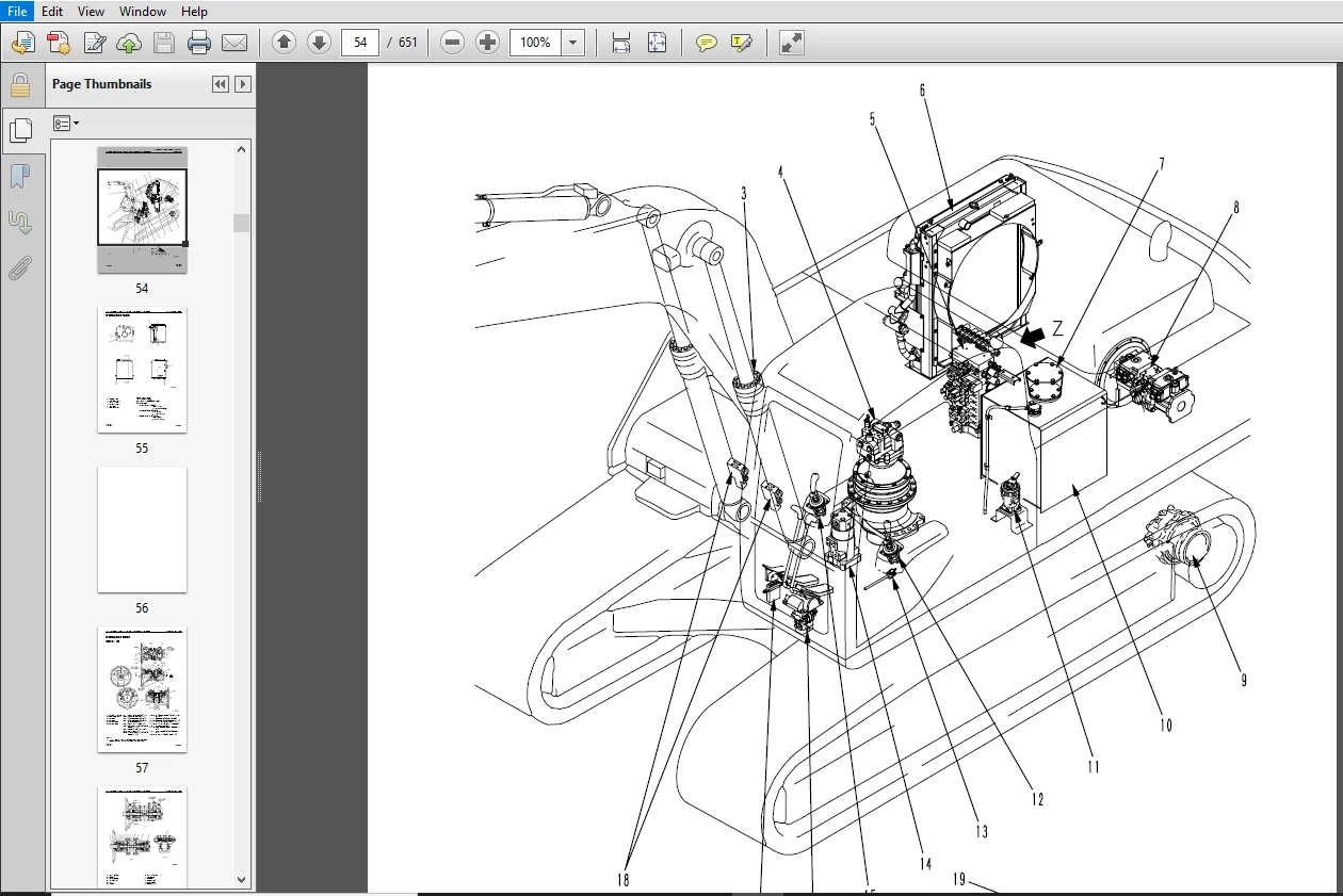
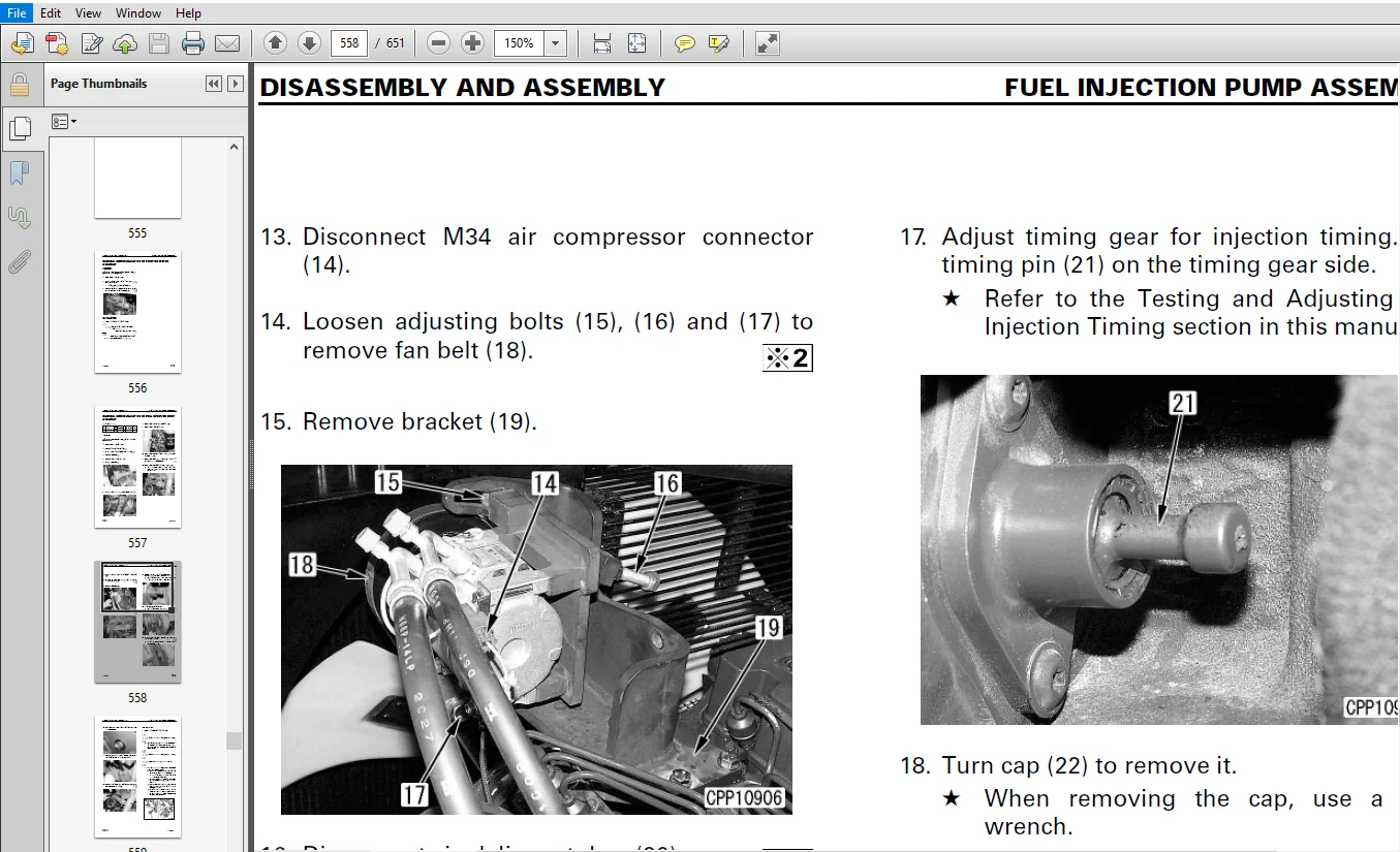
COVER................................................................................................................  1
CONTENTS.............................................................................................................  2
SAFETY...............................................................................................................  4
FOREWORD.............................................................................................................  6
01 GENERAL........................................................................................................... 24
	SPECIFICATION DIMENSION DRAWINGS................................................................................. 25
	SPECIFICATIONS................................................................................................... 27
	WEIGHT TABLE..................................................................................................... 29
	FUEL, COOLANT AND LUBRICANTS..................................................................................... 31
10 STRUCTURE, FUNCTION AND MAINTENANCE STANDARD...................................................................... 32
	Engine Related Parts............................................................................................. 33
	Radiator • Oil Cooler • Aftercooler.............................................................................. 34
	Power Train...................................................................................................... 35
	Final Drive...................................................................................................... 37
	Swing Machinery.................................................................................................. 39
	Swing Circle..................................................................................................... 41
	Track Frame • Recoil Spring...................................................................................... 43
	Idler............................................................................................................ 45
	Carrier roller................................................................................................... 47
	Track roller..................................................................................................... 48
	Track Shoe....................................................................................................... 49
	Hydraulic Equipment Layout Drawing............................................................................... 53
	Hydraulic Tank................................................................................................... 55
	Hydraulic Pump................................................................................................... 57
	Variable Volume Valve............................................................................................ 78
	Control Valve.................................................................................................... 81
	CLSS............................................................................................................. 97
	Self Pressure Reducing Valve.....................................................................................100
	Swing Motor......................................................................................................103
	Reverse Prevention Valve.........................................................................................109
	Center Swivel Joint..............................................................................................111
	Travel Motor.....................................................................................................112
	Travel Junction Valve............................................................................................122
	Travel PPC Shuttle Valve ........................................................................................125
	Valve Control....................................................................................................129
	Work Equipment • Swing PPC Valve.................................................................................130
	Travel PPC Valve.................................................................................................134
	Service PPC Valve ...............................................................................................143
	Solenoid Valve...................................................................................................146
	PPC Accumulator..................................................................................................148
	Return Oil Filter................................................................................................149
	Boom Hydraulic Drift Prevention Valve............................................................................151
	Quick Return Valve...............................................................................................157
	Lift Check Valve.................................................................................................159
	Attachment Circuit Selector Valve................................................................................160
	Hydraulic Cylinder...............................................................................................163
	Work Equipment...................................................................................................165
	Air Conditioner..................................................................................................171
	Engine Control...................................................................................................172
	Electronic Control System .......................................................................................180
	Multi Monitor System.............................................................................................204
	7-Segment Monitor System.........................................................................................224
	Sensor...........................................................................................................231
20 TESTING AND ADJUSTING.............................................................................................234
	STANDARD VALUE TABLE FOR ENGINE RELATED PARTS....................................................................235
	STANDARD VALUE TABLE FOR CHASSIS RELATED PARTS...................................................................236
	TESTING AND ADJUSTING............................................................................................244
	TROUBLESHOOTING..................................................................................................328
		POINTS TO REMEMBER WHEN TROUBLESHOOTING......................................................................329
		SEQUENCE OF EVENTS IN TROUBLESHOOTING........................................................................330
		POINTS TO REMEMBER WHEN CARRYING OUT MAINTENANCE.............................................................331
		CHECKS BEFORE TROUBLESHOOTING................................................................................339
		CLASSIFICATION AND STEPS FOR TROUBLESHOOTING.................................................................340
		CONNECTOR LOCATION CHART AND ELECTRICAL CIRCUIT DIAGRAM BY SYSTEM............................................345
		CONNECTION TABLE FOR CONNECTOR PIN NUMBERS...................................................................363
		TROUBLESHOOTING WHEN SERVICE CODE "ELECTRICAL SYSTEM" AND FAILURE CODE "MECHANICAL SYSTEM" ARE INDICATED.....386
		TROUBLESHOOTING OF ELECTRICAL SYSTEM (E-MODE)................................................................472
		TROUBLESHOOTING OF HYDRAULIC AND MECHANICAL SYSTEM (H-MODE)..................................................522
30 DISASSEMBLY AND ASSEMBLY..........................................................................................546
	HOW TO READ THIS MANUAL..........................................................................................548
	PRECAUTIONS WHEN PERFORMING OPERATION ...........................................................................550
	SPECIAL TOOL LIST................................................................................................552
	STARTING MOTOR ASSEMBLY .........................................................................................556
	FUEL INJECTION PUMP ASSEMBLY ....................................................................................557
	ENGINE FRONT SEAL................................................................................................561
	ENGINE REAR SEAL.................................................................................................562
	CYLINDER HEAD ASSEMBLY ..........................................................................................564
	RADIATOR ASSEMBLY ...............................................................................................570
	HYDRAULIC OIL COOLER ASSEMBLY ...................................................................................572
	ENGINE AND HYDRAULIC PUMP ASSEMBLIES ............................................................................574
	FINAL DRIVE ASSEMBLY ............................................................................................578
	DISASSEMBLY AND ASSEMBLY OF FINAL DRIVE ASSEMBLY.................................................................579
	SWING MOTOR, SWING MACHINERY ASSEMBLY............................................................................589
	DISASSEMBLY AND ASSEMBLY OF SWING MOTOR, SWING MACHINERY ASSEMBLY................................................590
	CARRIER ROLLER ASSEMBLY..........................................................................................598
	TRACK ROLLER ASSEMBLY............................................................................................599
	IDLER ASSEMBLY ..................................................................................................600
	RECOIL SPRING ASSEMBLY ..........................................................................................603
	SPROCKET ........................................................................................................605
	TRACK SHOE ASSEMBLY..............................................................................................606
	SWING CIRCLE ASSEMBLY............................................................................................608
	REVOLVING FRAME ASSEMBLY ........................................................................................609
	CENTER SWIVEL JOINT ASSEMBLY.....................................................................................612
	DISASSEMBLY AND ASSEMBLY OF CENTER SWIVEL JOINT ASSEMBLY.........................................................614
	HYDRAULIC TANK ASSEMBLY .........................................................................................615
	CONTROL VALVE ASSEMBLY...........................................................................................617
	DISASSEMBLY AND ASSEMBLY OF CONTROL VALVE ASSEMBLY...............................................................620
	HYDRAULIC PUMP ASSEMBLY .........................................................................................622
	OIL SEAL IN HYDRAULIC PUMP INPUT SHAFT...........................................................................625
	WORK EQUIPMENT PPC VALVE ASSEMBLY................................................................................626
	TRAVEL PPC VALVE ASSEMBLY .......................................................................................627
	HYDRAULIC CYLINDER ASSEMBLY .....................................................................................628
	WORK EQUIPMENT ASSEMBLY .........................................................................................634
	AIR CONDITIONER UNIT ASSEMBLY....................................................................................637
	COUNTERWEIGHT ASSEMBLY ..........................................................................................640
	OPERATOR’S CAB ASSEMBLY .........................................................................................641
	MONITOR ASSEMBLY.................................................................................................643
	GOVERNOR PUMP CONTROLLER ASSEMBLY ...............................................................................644
90 OTHERS............................................................................................................646
	Hydraulic Circuit Diagram........................................................................................647
	Electrical Circuit Diagram (1/4).................................................................................648
	Electrical Circuit Diagram (2/4).................................................................................649
	Electrical Circuit Diagram (3/4).................................................................................650
	Electrical Circuit Diagram (4/4).................................................................................651
KOMATSU PC360-7 HYDRAULIC EXCAVATOR SHOP MANUAL SMEH3607M0 – PDF DOWNLOAD:
IMAGES PREVIEW OF THE MANUAL:
PLEASE NOTE:
- This is not a physical manual but a digital manual – meaning no physical copy will be couriered to you. The manual can be yours in the next 2 mins as once you make the payment, you will be directed to the download page IMMEDIATELY.
- This is the same manual used by the dealers inorder to diagnose your vehicle of its faults.
- Require some other service manual or have any queries: please WRITE to us at [email protected]


Brandon Tristen –