
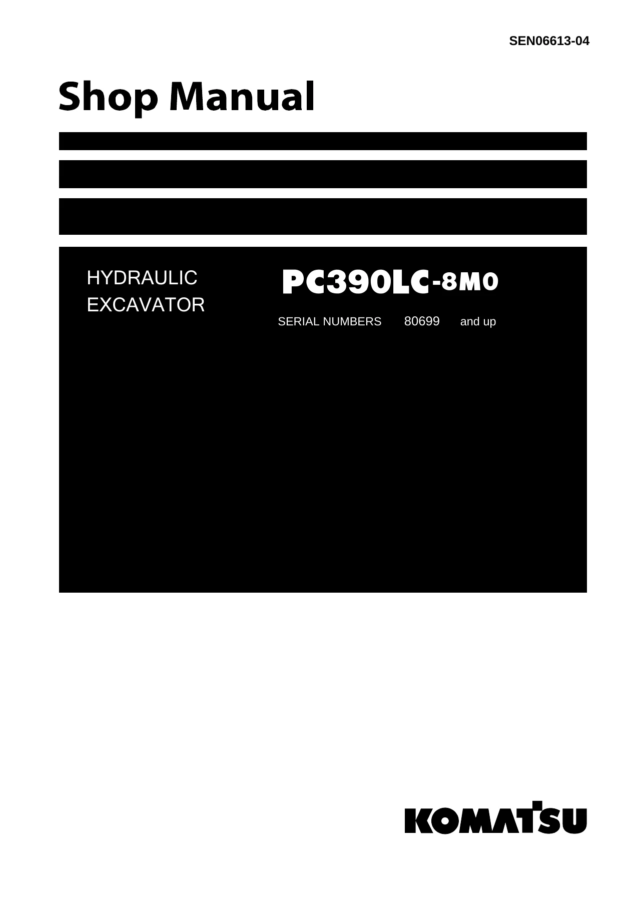
Komatsu PC390LC-8M0 Hydraulic Excavator Shop Manual – SEN06613-04 – Serial 80699 and Up
Original price was: $69.95.$49.95Current price is: $49.95.
Complete Komatsu PC390LC-8M0 shop manual covering specifications, structure and function, standard values, testing and adjusting, troubleshooting, disassembly and assembly, air conditioner, and hydraulic/electrical diagrams. Document SEN06613-04 for serial 80699 and up.
Description
Komatsu PC390LC-8M0 Shop Manual – SEN06613-04
This is the complete Komatsu PC390LC-8M0 hydraulic excavator shop manual, document number SEN06613-04, covering machines from serial number 80699 and up. It is the same comprehensive workshop reference used by professional technicians for maintaining, diagnosing, and repairing the PC390LC-8M0, with detailed procedures, specifications, and illustrations across every major system.
File Details
- Manual Type: Shop Manual
- Brand: Komatsu
- Model: PC390LC-8M0
- Document Number: SEN06613-04
- Serial Number: 80699 and Up
- Language: English
- File Format: PDF
- Page Count: Approximately 1,122 pages
Chapters Covered
- 00 Index and foreword
- 01 Specification
- 10 Structure, function and maintenance standard
- 20 Standard value table
- 30 Testing and adjusting
- 40 Troubleshooting
- 50 Disassembly and assembly
- 80 Appendix
- 90 Diagrams and drawings
00 Index and Foreword
This opening chapter provides the safety and general information every technician needs before starting work on the PC390LC-8M0. It includes the foreword, how to read the shop manual, explanations of maintenance standard terms, handling procedures for fuel system devices, intake system parts, hydraulic equipment, and electrical equipment. It also covers the push-pull type coupler connection and disconnection method, how to read electric wire codes, precautions when performing operation, practical use of KOMTRAX, a standard tightening torque table, a list of abbreviations, and conversion tables. The safety notices here are not optional reading — they establish the correct handling of high-pressure fuel, hydraulic components, and electrical circuits that the rest of the manual assumes.
01 Specification
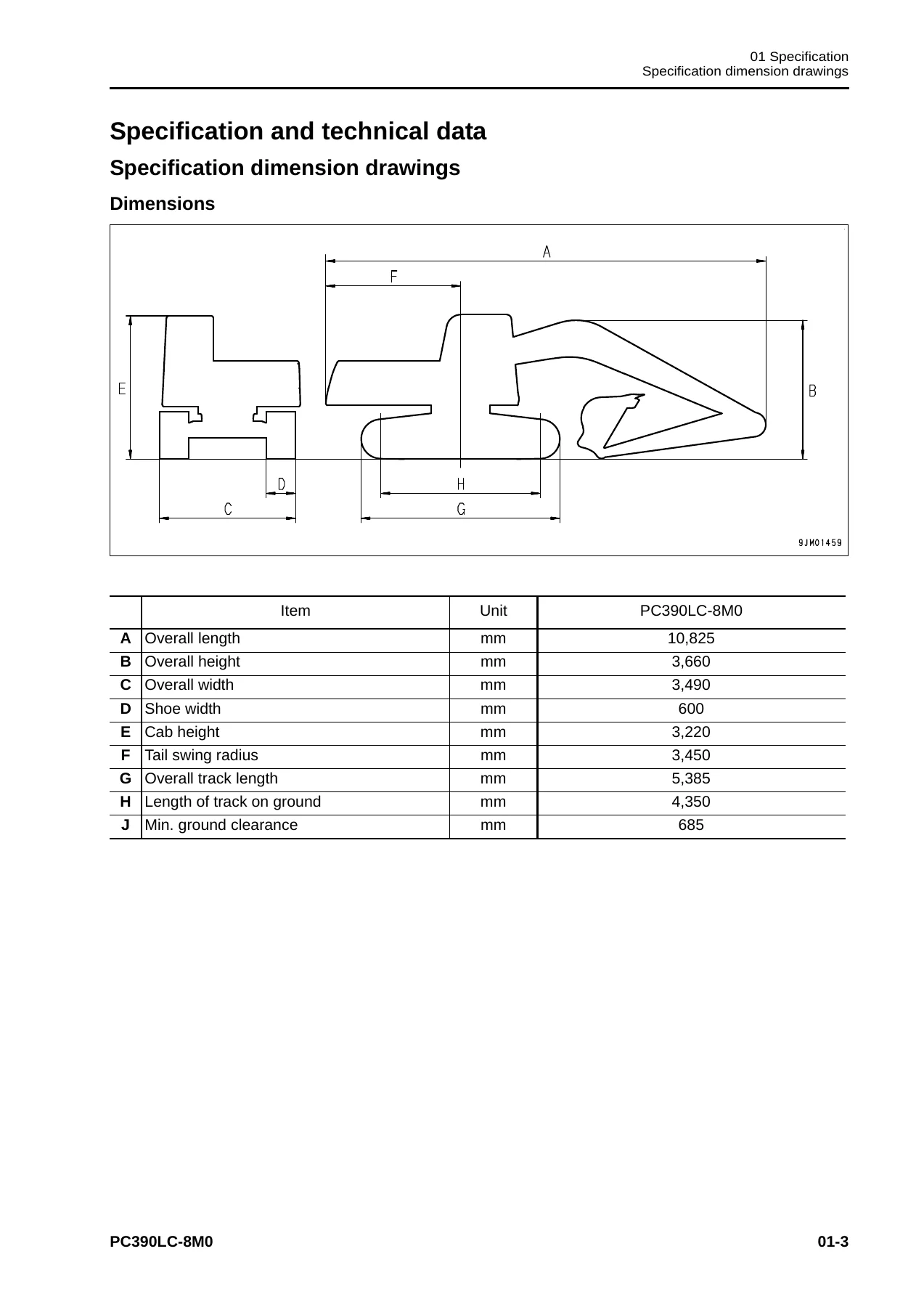
The specification chapter provides the technical data and dimension drawings for the PC390LC-8M0. It includes specification dimension drawings, full specifications, a weight table, and a table of fuel, coolant, and lubricants. This section gives you the baseline machine data — working ranges, dimensions, weight distribution, and fluid capacities — that you will reference throughout testing, adjusting, and repair procedures. The dimension drawings are particularly useful when verifying machine posture or checking clearances against standard values.
10 Structure, Function and Maintenance Standard
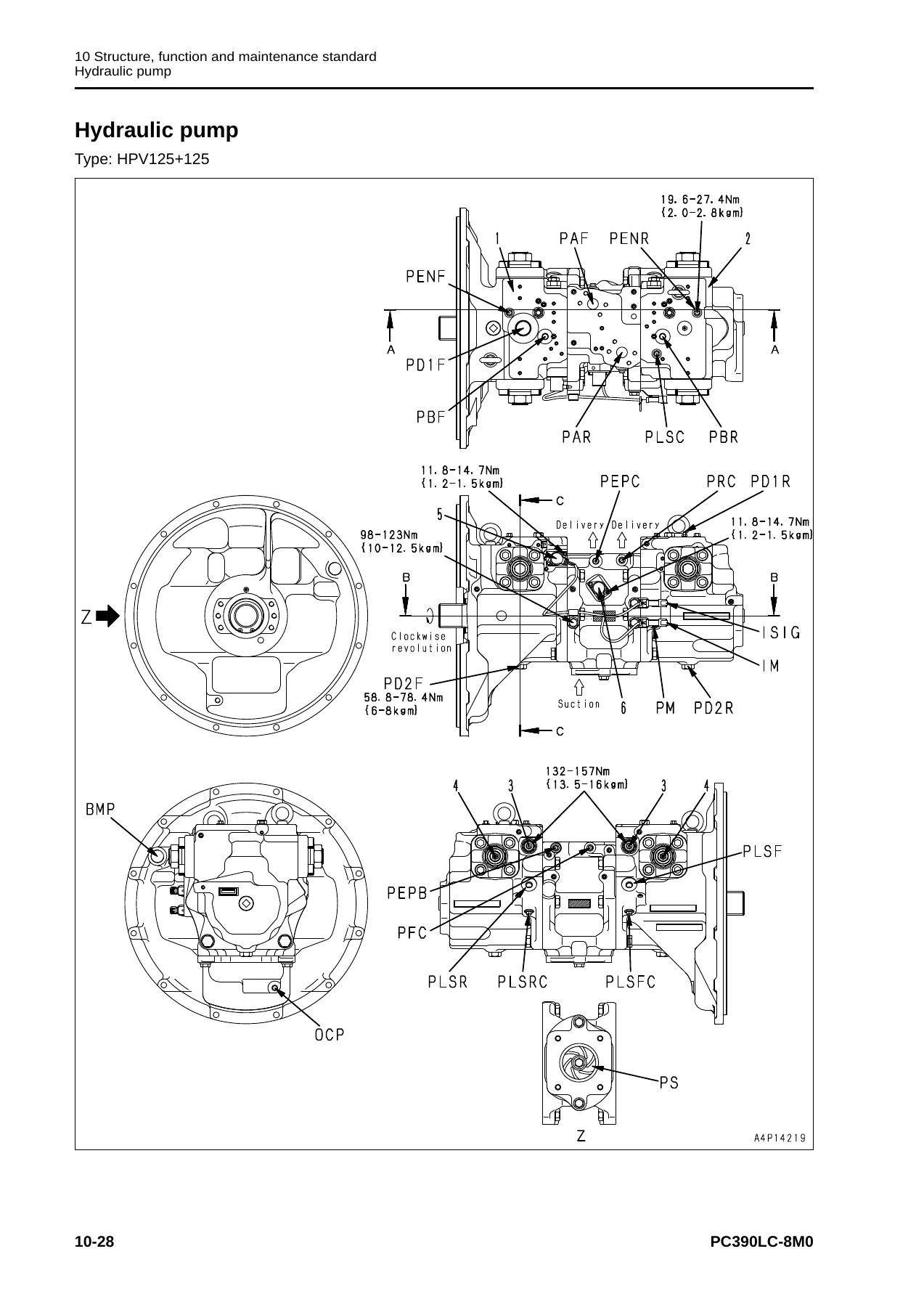
This is the largest chapter and covers the structure, function, and maintenance standards for every major system on the machine. It begins with the engine and cooling system, including engine related parts and the radiator, oil cooler, and aftercooler. The power train section covers the power train layout, swing circle, swing machinery, final drive, and sprocket. The undercarriage and frame section covers the track frame and recoil spring, idler, carrier roller, track roller, and track shoe. The hydraulic system section is extensive, covering the hydraulic equipment layout drawing, hydraulic tank and filter, hydraulic pump, control valve, CLSS (Closed-center Load Sensing System), functions and operation by valve, attachment circuit selector valve, hydraulic drift prevention valve, valve control, PPC valve, solenoid valve, PPC accumulator, center swivel joint, travel motor, swing motor, work equipment cylinder, work equipment, and dimensions of components. The electrical system section covers the engine control system, electronic control system, machine monitor system, sensors, and KOMTRAX system. Maintenance standards with criteria and remedies are provided throughout, giving you the wear limits and clearance values needed to judge whether a component can be reused or must be replaced.
20 Standard Value Table
The standard value table provides the criteria for testing, adjusting, and troubleshooting. It includes a standard service value table, a standard value table for engine related parts, and a standard value table for chassis related parts. These are the target values for a new or freshly repaired machine, and they serve as the benchmark against which you measure actual machine performance. The table includes values for engine speed, intake pressure, exhaust gas color, valve clearance, compression pressure, blowby pressure, oil pressure, and more, along with repair limits where applicable.
30 Testing and Adjusting
This chapter explains the tools and procedures for testing and adjusting the PC390LC-8M0. It opens with related information on testing and adjusting, tools for testing, adjusting and troubleshooting, and sketches of special tools. The engine and cooling system section covers testing engine speed, air boost pressure, exhaust gas color, adjusting valve clearance, testing compression pressure, blowby pressure, engine oil pressure, fuel pressure, handling during cylinder cutout operation, handling during no-injection cranking operation, testing fuel return rate and leakage, bleeding air from the fuel circuit, checking the fuel circuit for leakage, testing and adjusting air compressor belt tension, replacing the fan belt, and replacing the alternator belt. The power train section covers testing clearance in swing circle bearings. The undercarriage and frame section covers testing and adjusting track tension. The hydraulic system section is extensive, covering testing and adjusting oil pressure in work equipment, swing and travel circuits, testing control circuit oil pressure, testing and adjusting pump PC control circuit oil pressure, testing and adjusting pump LS control circuit oil pressure, testing solenoid valve output pressure, testing PPC valve output pressure, adjusting play of work equipment and swing PPC valves, inspecting locations of hydraulic drift of work equipment, releasing remaining pressure in the hydraulic circuit, testing oil leakage amount, bleeding air from various parts, testing and charging accumulator nitrogen gas pressure for attachment (low and high pressure sides), and replacing the accumulator bladder. The electrical system section covers special functions of the machine monitor, handling the voltage circuit of the engine controller, preparation work for troubleshooting the electrical system, and the procedure for testing diodes. A PM clinic section provides a structured preventive maintenance inspection service.
40 Troubleshooting
The troubleshooting chapter is organized to help you diagnose and repair faults efficiently. It begins with general information on troubleshooting, including symptom and troubleshooting numbers, sequence of events in troubleshooting, checks before troubleshooting, classification and procedures for troubleshooting, information in the troubleshooting table, connector list and layout, connection table for connector pin numbers, T-branch box and T-branch adapter table, troubleshooting method for open circuit in wiring harness of pressure sensor system, failure codes table, and fuse locations. The manual then provides troubleshooting by failure code, covering a comprehensive list of codes from A/C sensor faults through engine controller issues, sensor errors, injector circuit errors, CAN communication faults, and solenoid valve faults. Each failure code entry includes the failure name, detail of failure, action of controller, problem on machine, related information, and a cause/procedure table with measuring locations and criteria. The electrical system (E-mode) troubleshooting section covers symptoms such as engine does not start, preheater does not operate, machine monitor displays nothing, gauges not indicating properly, working mode does not change, travel speed does not change, alarm buzzer issues, wiper and washer problems, KOMTRAX system issues, and more. The hydraulic and mechanical system (H-mode) troubleshooting section covers symptoms such as all work equipment lack power, engine speed drops or stalls, no work equipment/swing/travel movement, abnormal noise from hydraulic pump, slow or weak boom/arm/bucket, hydraulic drift, time lag, combined operation issues, travel problems, and swing problems. The engine (S-mode) troubleshooting section covers starting performance, engine not starting, rough running, stalling, lack of output, exhaust smoke, oil consumption, fuel consumption, coolant issues, oil pressure drops, overheating, abnormal noise, and vibration.
50 Disassembly and Assembly
This chapter provides the procedures for removing, installing, disassembling, and assembling components. It begins with related information on disassembly and assembly, how to read the manual, a coating materials list, a special tools list, and sketches of special tools. The engine and cooling system section covers removal and installation of the supply pump assembly, engine front oil seal, engine rear oil seal, cylinder head assembly, radiator assembly, hydraulic oil cooler assembly, aftercooler assembly, and engine and hydraulic pump assembly. The power train system section covers removal and installation of the travel motor and final drive assembly, disassembly and assembly of the final drive assembly, removal and installation of the swing motor and swing machinery assembly, disassembly and assembly of the swing motor and swing machinery assembly, and removal and installation of the swing circle assembly. The undercarriage and frame section covers disassembly and assembly of the carrier roller assembly, track roller assembly, idler assembly, and recoil spring assembly, removal and installation of the sprocket, expansion and installation of the track shoe assembly, removal and installation of the revolving frame assembly, and removal and installation of the counterweight assembly. The hydraulic system section covers removal and installation of the center swivel joint assembly, disassembly and assembly of the center swivel joint assembly, removal and installation of the hydraulic tank assembly, removal and installation of the control valve assembly, disassembly and assembly of the control valve assembly, removal and installation of the hydraulic pump assembly, removal and installation of the hydraulic pump input shaft oil seal, disassembly and assembly of the work equipment PPC valve assembly, disassembly and assembly of the travel PPC valve assembly, and disassembly and assembly of the work equipment cylinder assembly. The work equipment section covers removal and installation of the work equipment assembly. The cab and its attachments section covers removal and installation of the operator’s cab assembly, operator’s cab glass (adhered window glass), front window assembly, and floor frame assembly. The electrical system section covers removal and installation of the air conditioner unit assembly, KOMTRAX terminal assembly, machine monitor assembly, pump controller assembly, and engine controller assembly. Tightening torques, coating materials, and fluid quantities are specified throughout.
80 Appendix – Air Conditioner
The appendix covers the air conditioner system in detail. It includes precautions for refrigerant, air conditioner components, configuration and function of the refrigeration cycle, outline of the refrigeration cycle, air conditioner unit, air conditioner controller, compressor, condenser, receiver drier, and sensors. It provides the procedure for testing and troubleshooting, circuit diagram and arrangement of connector pins, system diagram, parts and connectors layout, testing air leaks (duct), testing with the self-diagnosis function, testing vent (mode) changeover, testing FRESH/RECIRC air changeover, testing the sunlight sensor, testing the (dual) pressure switch for refrigerant, and testing relays. Troubleshooting charts 1 and 2 provide systematic diagnostic procedures, and the troubleshooting table gives information for each failure code related to the air conditioner. It also covers troubleshooting for the power supply and CAN communication system, compressor and refrigerant system, blower motor system, and FRESH/RECIRC air changeover. The chapter closes with troubleshooting with gauge pressure, connection of the service tool, precautions for disconnecting and connecting air conditioner piping, and handling of compressor oil.
90 Diagrams and Drawings
The final chapter provides the hydraulic and electrical diagrams and drawings. It includes symbols in the hydraulic circuit diagram, the hydraulic circuit diagram itself, symbols in the electric circuit diagram, and the electrical circuit diagram. These diagrams are essential for tracing circuits, understanding system operation, and diagnosing electrical and hydraulic faults. The hydraulic circuit diagram shows the complete hydraulic system layout, while the electrical circuit diagram provides the full wiring schematic for the machine.
What This Komatsu PC390LC-8M0 Shop Manual Enables You to Do
With this manual, you can perform the full range of professional service tasks on the PC390LC-8M0. You can test and adjust engine speed, boost pressure, valve clearance, compression pressure, blowby pressure, and oil pressure. You can diagnose and repair faults in the hydraulic system, including the pump, control valve, CLSS, PPC valve, travel motor, swing motor, and cylinders. You can troubleshoot electrical faults using the failure code tables, connector layouts, and circuit diagrams. You can disassemble and assemble the engine, power train, undercarriage, hydraulic components, work equipment, cab, and electrical components using the specified procedures and tightening torques. You can service the air conditioner system, including refrigerant handling, component replacement, and self-diagnosis. The standard value tables and maintenance standards give you the exact criteria to judge wear and determine whether a component needs replacement.
Correct procedures and specifications matter because the PC390LC-8M0 is a 39,900 kg class hydraulic excavator with complex systems — the CLSS hydraulic system, the common rail fuel injection system, and the electronic control system all require precise handling. Using the wrong torque, clearance, or adjustment value can lead to premature failure, poor performance, or unsafe operation. This manual provides the manufacturer’s recommended values and procedures, so you can work with confidence.
IMAGES PREVIEW
Delivery is instant. After payment, you receive the PDF download link immediately — no shipping, no waiting. The PDF works on any device: computer, tablet, or smartphone. You can print the pages you need for the workshop, or keep the entire manual on a device for quick reference. Whether you are a professional technician, a fleet maintenance manager, or an owner-operator who does their own repairs, this Komatsu PC390LC-8M0 shop manual gives you the information you need to keep the machine running correctly.
Reviews
There are no reviews yet.