★ TRUSTED BY 321,897+ PROFESSIONALS WORLDWIDE
🏢
Trusted Business
Verified & Licensed
🛡️
Virus Free Files
100% Safe Downloads
🔒
Secure Payment
SSL Protected
Instant Delivery
Available Immediately
Sale!

Komatsu PC400-7E0 PC400LC-7E0 PC450-7E0 PC450LC-7E0 Excavator Shop Manual PDF SEN03578-03

Original price was: $39.95.Current price is: $24.95.

Complete Komatsu shop manual SEN03578-03 for PC400-7E0, PC400LC-7E0, PC450-7E0 and PC450LC-7E0 hydraulic excavators. Full PDF covering specifications, hydraulic and electrical systems, testing and adjusting, troubleshooting by failure code, and disassembly and assembly. Instant download.

Instant PDF Download
Available immediately
💾
Save to Your Device
Download & keep forever
🛡️
Antivirus Scanned
100% virus-free
🌍
Trusted Worldwide
175,000+ customers

Description

Komatsu PC400-7E0 / PC400LC-7E0 / PC450-7E0 / PC450LC-7E0 Shop Manual – SEN03578-03

This is the full Komatsu shop manual released under form number SEN03578-03, covering the PC400-7E0, PC400LC-7E0, PC450-7E0 and PC450LC-7E0 hydraulic excavators. It is the workshop-level reference used for specification lookup, system diagnosis, hydraulic and electrical troubleshooting, component overhaul and field repair. The document is written in English and organised as a multi-part shop manual containing specification data, structure and function of major systems, standard service values, testing and adjusting procedures, failure-code driven troubleshooting, disassembly and assembly, and complete hydraulic and electrical diagrams.

File Details

  • Manual type: Shop Manual (workshop service reference)
  • Brand: Komatsu
  • Models covered: PC400-7E0, PC400LC-7E0, PC450-7E0, PC450LC-7E0
  • Document number: SEN03578-03
  • Language: English
  • File format: PDF
  • Serial number coverage: PC400-7E0 60001-60089 and 65001 and up; PC400LC-7E0 60001-60089 and 65001 and up; PC450-7E0 30001-30058 and 65001 and up; PC450LC-7E0 30001-30058 and 65001 and up
  • Engine covered: Komatsu SAA6D125E-5
  • Publication origin: Printed in Japan

Chapters Covered

The manual follows Komatsu’s standard shop-manual composition and is broken into the following top-level parts, each carrying its own form number inside SEN03578-03:

  • 00 Index and Foreword – Composition of shop manual, safety notice, how to read the shop manual, explanation of terms for maintenance standard, handling of electric equipment and hydraulic components, handling of engine connectors, how to read electric wire code, precautions during operation, push-pull coupler handling, standard tightening torque table, conversion tables.
  • 01 Specification – Specification dimension drawings, working ranges, specifications (backhoe and loading shovel), weight table, table of fuel, coolant and lubricants.
  • 10 Structure, Function and Maintenance Standard – Engine and cooling system, power train (final drive, sprocket, swing machinery, swing circle), undercarriage and frame (track frame, recoil spring, idler, carrier roller, track roller, track shoe), hydraulic system Part 1 (equipment layout, hydraulic tank and filter, hydraulic pump), hydraulic system Part 2 (control valve, CLSS, merge-divider valve, attachment circuit selector, holding valve), hydraulic system Part 3 (valve control, PPC valve, solenoid valve, PPC accumulator, return oil filter, center swivel joint, travel motor, swing motor, hydraulic cylinder), work equipment, cab and its attachments (air conditioner piping), electrical system (engine control, electronic control system, monitor system, sensors, KOMTRAX).
  • 20 Standard Value Table – Standard service value tables for engine related parts and for chassis related parts (backhoe and loading shovel specifications).
  • 30 Testing and Adjusting – Testing and adjusting Part 1 (engine speed, boost pressure, exhaust temperature and gas colour, valve clearance, compression pressure, blow-by pressure, engine oil pressure, EGR and bypass valve drive pressure, fuel system handling, fuel pressure and return rate, belt tension, swing circle bearing clearance, track shoe tension, work equipment/swing/travel circuit pressure, pump PC and LS control circuits, solenoid valve and PPC output pressures, hydraulic drift inspection, residual pressure release, oil leakage measurement, bleeding air), Part 2 (special functions of the machine monitor), Part 3 (KOMTRAX terminal turn-on, KOMTRAX lamp indications, engine controller voltage handling, electrical troubleshooting preparation, diode testing, Pm clinic service, undercarriage troubleshooting report).
  • 40 Troubleshooting – Failure code table and fuse locations, information related to troubleshooting, troubleshooting by failure code (Parts 1-3), troubleshooting of the electrical system (E-mode), troubleshooting of the hydraulic and mechanical system (H-mode), and troubleshooting of the engine (S-mode).
  • 50 Disassembly and Assembly – General information on disassembly and assembly, engine and cooling system, power train, undercarriage and frame, hydraulic system, work equipment, cab and its attachments, electrical system.
  • 90 Diagrams and Drawings – Hydraulic circuit diagrams and drawings, electrical circuit diagrams and drawings, connector list and stereogram.

Complete PDF Bookmark Tree

Complete Bookmarks

The complete bookmarks in the “Komatsu PC400-7E0 PC400LC-7E0 PC450-7E0 PC450LC-7E0 Excavator Shop Manual PDF SEN03578-03” are as follows:

COVERp. 1
00 Index and forewordp. 2
Indexp. 2
Composition of shop manualp. 3
Table of contentsp. 5
Foreword and general informationp. 14
Safety noticep. 15
How to read the shop manualp. 20
Explanation of terms for maintenance standardp. 22
Handling of electric equipment and hydraulic componentp. 24
Handling of connectors newly used for enginesp. 33
How to read electric wire codep. 36
Precautions when carrying out operationp. 39
Method of disassembling and connecting push-pull type couplerp. 42
Standard tightening torque tablep. 45
Conversion tablep. 49
01 Specificationp. 56
Specification and technical datap. 56
Specification dimension drawingsp. 57
Specificationsp. 61
Weight tablep. 67
Table of fuel, coolant and lubricantsp. 71
10 Structure, function and maintenance standardp. 74
Engine and cooling systemp. 74
Engine related partsp. 75
Radiator, oil cooler and aftercoolerp. 76
Power trainp. 78
Power trainp. 79
Final drivep. 81
Sprocketp. 83
Swing machineryp. 85
Swing circlep. 87
Undercarriage and framep. 90
Track frame and recoil springp. 91
Idlerp. 93
Carrier rollerp. 95
Track rollerp. 96
Track shoep. 97
Hydraulic system, Part 1p. 102
Hydraulic equipment layout drawingp. 103
Hydraulic tank and filterp. 105
Hydraulic pumpp. 107
Hydraulic system, Part 2p. 132
Control valvep. 133
CLSSp. 157
Functions and operation by valvep. 161
Merge-divider valvep. 178
Attachment circuit selector valvep. 203
Holding valvep. 205
Hydraulic system, Part 3p. 212
Valve controlp. 213
PPC valvep. 215
Solenoid valvep. 231
PPC accumulatorp. 233
Return oil filterp. 234
Center swivel jointp. 235
Travel motorp. 236
Swing motorp. 248
Hydraulic cylinderp. 257
Work equipmentp. 262
Work equipmentp. 263
Dimensions of componentsp. 267
Cab and its attachmentsp. 272
Air conditioner pipingp. 273
Electrical systemp. 276
Engine controlp. 277
Electronic control systemp. 286
Monitor systemp. 311
Sensorp. 329
KOMTRAX systemp. 332
20 Standard value tablep. 336
Standard service value tablep. 336
Standard value table for engine related partsp. 337
Standard value table for chassis related parts (Backhoe specification)p. 338
Standard value table for chassis related parts (Loading shovel specification)p. 347
30 Testing and adjustingp. 358
Testing and adjusting, Part 1p. 358
Tools for testing, adjusting and troubleshootingp. 360
Measuring engine speedp. 364
Measuring air boost pressurep. 365
Measuring exhaust temperaturep. 366
Measuring exhaust gas colorp. 367
Adjusting valve clearancep. 368
Measuring compression pressurep. 370
Measuring blow-by pressurep. 372
Measuring engine oil pressurep. 373
Measuring EGR valve and bypass valve drive pressurep. 374
Handling fuel system partsp. 375
Releasing residual pressure from fuel systemp. 375
Measuring fuel pressurep. 376
Handling during cylinder cut-out operationp. 377
Handling during no injection cranking operationp. 377
Measuring fuel return rate and leakagep. 378
Bleeding air from fuel circuitp. 381
Checking fuel circuit for leakagep. 383
Checking and adjusting fan belt and alternator belt tensionp. 384
Checking and adjusting air conditioner compressor belt tensionp. 385
Measuring swing circle bearing clearancep. 386
Checking and adjusting track shoe tensionp. 387
Measuring and adjusting oil pressure in work equipment, swing, and travel circuitsp. 388
Measuring control circuit basic pressurep. 392
Checking and adjusting pump PC control circuit oil pressurep. 393
Checking and adjusting pump LS control circuit oil pressurep. 396
Measuring solenoid valve output pressurep. 401
Measuring PPC valve output pressurep. 404
Adjusting play of work equipment and swing PPC valvesp. 405
Inspecting locations of hydraulic drift of work equipmentp. 406
Releasing residual pressure from hydraulic circuitp. 408
Measuring oil leakage amountp. 409
Bleeding air from various partsp. 412
Testing and adjusting, Part 2p. 416
Special functions of machine monitorp. 417
Testing and adjusting, Part 3p. 446
Procedure for turning on KOMTRAX terminalp. 447
Indication by KOMTRAX terminal lampsp. 450
Handling voltage circuit of engine controllerp. 453
Preparation work for troubleshooting of electrical systemp. 454
Procedure for testing diodesp. 459
Pm clinic servicep. 460
Undercarriage troubleshooting reportp. 467
40 Troubleshootingp. 470
Failure code table and fuse locationsp. 470
Failure codes tablep. 471
Before carrying out troubleshooting when failure code is displayedp. 475
Information related to troubleshootingp. 480
Points to remember when troubleshootingp. 481
Sequence of events in troubleshootingp. 482
Checks before troubleshootingp. 483
Classification and troubleshooting stepsp. 484
Information in troubleshooting tablep. 485
Connection table for connector pin numbersp. 490
T- branch box and T- branch adapter tablep. 526
Troubleshooting by failure code (Display of code), Part 1p. 530
Failure code [AA10NX] Aircleaner Cloggingp. 533
Failure code [AB00KE] Charge Voltage Lowp. 535
Failure code [B@BAZG] Eng Oil Press. Lowp. 537
Failure code [B@BAZK] Eng. Oil Level Lowp. 539
Failure code [B@BCNS] Eng. Water Overheatp. 541
Failure code [B@BCZK] Eng. Water Lvl Lowp. 543
Failure code [B@HANS] Hydr. Oil Overheatp. 545
Failure code [CA111] ECM Critical Internal Failurep. 547
Failure code [CA115] Eng Ne and Bkup Speed Sens Errorp. 549
Failure code [CA122] Chg Air Press Sensor High Errorp. 550
Failure code [CA123] Chg Air Press Sensor Low Errorp. 552
Failure code [CA131] Throttle Sensor High Errorp. 553
Failure code [CA132] Throttle Sensor Low Errorp. 555
Failure code [CA135] Eng Oil Press Sensor High Errorp. 556
Failure code [CA141] Eng Oil Press Sensor Low Errorp. 558
Failure code [CA144] Coolant Temp Sens High Errorp. 559
Failure code [CA145] Coolant Temp Sens Low Errorp. 561
Failure code [CA153] Chg Air Temp Sensor High Errorp. 563
Failure code [CA154] Chg Air Temp Sensor Low Errorp. 565
Failure code [CA187] Sens Supply 2 Volt Low Errorp. 567
Failure code [CA221] Ambient Press Sens High Errorp. 569
Failure code [CA222] Ambient Press Sens Low Errorp. 571
Failure code [CA227] Sens Supply 2 Volt High Errorp. 572
Failure code [CA234] Eng Overspeedp. 574
Failure code [CA238] Ne Speed Sens Supply Volt Errorp. 575
Failure code [CA263] Fuel Temp Sensor High Errorp. 577
Failure code [CA265] Fuel Temp Sensor Low Errorp. 579
Failure code [CA271] IMV/PCV1 Short Errorp. 580
Failure code [CA272] IMV/PCV1 Open Errorp. 581
Failure code [CA273] PCV2 Short Errorp. 583
Failure code [CA274] PCV2 Open Errorp. 584
Failure code [CA322] Inj #1 (L/B#1) Open/Short Errorp. 585
Failure code [CA323] Inj #5 (L/B#5) Open/Short Errorp. 587
Failure code [CA324] Inj #3 (L/B#3) Open/Short Errorp. 589
Failure code [CA325] Inj #6 (L/B#6) Open/Short Errorp. 591
Failure code [CA331] Inj #2 (L/B#2) Open/Short Errorp. 593
Failure code [CA332] Inj #4 (L/B#4) Open/Short Errorp. 595
Troubleshooting by failure code (Display of code), Part 2p. 598
Failure code [CA342] Calibration Code Incompatibilityp. 600
Failure code [CA351] Injectors Drive Circuit Errorp. 601
Failure code [CA352] Sens Supply 1 Volt Low Errorp. 603
Failure code [CA386] Sens Supply 1 Volt High Errorp. 605
Failure code [CA441] Battery Voltage Low Errorp. 607
Failure code [CA442] Battery Voltage High Errorp. 609
Failure code [CA449] Rail Press Very High Errorp. 611
Failure code [CA451] Rail Press Sensor High Errorp. 615
Failure code [CA452] Rail Press Sensor Low Errorp. 617
Failure code [CA553] Rail Press High Errorp. 619
Failure code [CA554] Rail Press Sensor In Range Errorp. 620
Failure code [CA559] Rail Press Low Errorp. 621
Failure code [CA689] Eng Ne Speed Sensor Errorp. 625
Failure code [CA731] Eng Bkup Speed Sens Phase Errorp. 627
Failure code [CA757] All Persistent Data Lost Errorp. 628
Failure code [CA778] Eng Bkup Speed Sensor Errorp. 629
Failure code [CA1228] EGR Valve Servo Error 1p. 631
Failure code [CA1625] EGR Valve Servo Error 2p. 632
Failure code [CA1633] KOMNET Datalink Timeout Errorp. 633
Failure code [CA2185] Throt Sens Sup Volt High Errorp. 635
Failure code [CA2186] Throt Sens Sup Volt Low Errorp. 637
Failure code [CA2249] Rail Press Very Low Errorp. 638
Failure code [CA2271] EGR Valve Lift Sens High Errorp. 639
Failure code [CA2272] EGR Valve Lift Sens Low Errorp. 641
Failure code [CA2351] EGR Valve Sol Current High Errorp. 643
Failure code [CA2352] EGR Valve Sol Current Low Errorp. 645
Failure code [CA2555] Grid Htr Relay Volt Low Errorp. 647
Failure code [CA2556] Grid Htr Relay Volt High Errorp. 649
Failure code [D110KB] Battery Relay Drive Short Circuitp. 651
Failure code [D196KA] Service Return Relay Open Circuitp. 653
Failure code [D196KB] Service Return Relay Short Circuitp. 655
Failure code [DA25KP] 5V Sensor 1 Power Abnormalityp. 657
Failure code [DA80MA] Auto. Lub. Abnormal.p. 659
Troubleshooting by failure code (Display of code), Part 3p. 662
Failure code [DA2RMC] Pump Comm. Abnormalityp. 665
Failure code [DA2SKQ] Model Selection Abnormalityp. 667
Failure code [DAFRMC] Monitor Comm. Abnormalityp. 669
Failure code [DGH2KB] Hydr Oil Sensor Short Circuitp. 671
Failure code [DHPAMA] F Pump Press Sensor Abnormalityp. 673
Failure code [DHPBMA] R Pump Press Sensor Abnormalityp. 675
Failure code [DHS3MA] Arm Curl PPC Press Sensor Abnormalityp. 677
Failure code [DHS4MA] Bucket Curl PPC Press Sensor Abnormalityp. 679
Failure code [DW43KA] Travel Speed Sol. Open Circuitp. 681
Failure code [DW43KB] Travel Speed Sol. Short Circuitp. 683
Failure code [DW45KA] Swing Brake Sol. Open Circuitp. 685
Failure code [DW45KB] Swing Brake Sol. Short Circuitp. 689
Failure code [DW91KA] Travel Junction Sol. Open Circuitp. 691
Failure code [DW91KB] Travel Junction Sol. Short Circuitp. 693
Failure code [DWJ0KA] Merge-divider Sol. Open Circuitp. 695
Failure code [DWJ0KB] Merge-Divider Sol. Short Circuitp. 697
Failure code [DWK0KA] 2-stage Relief Sol. Open Circuitp. 699
Failure code [DWK0KB] 2-stage Relief Sol. Short Circuitp. 701
Failure code [DXA0KA] PC-EPC Sol. Open Circuitp. 703
Failure code [DXA0KB] PC-EPC Sol. Short Circuitp. 705
Failure code [DXE0KA] LS-EPC Sol. Open Circuitp. 707
Failure code [DXE0KB] LS-EPC Sol. Short Circuitp. 709
Failure code [DXE4KA] Service Current EPC Open Circuitp. 711
Failure code [DXE4KB] Service Current EPC Short Circuitp. 712
Failure code [DY20KA] Wiper Working Abnormalityp. 713
Failure code [DY20MA] Wiper Parking Abnormalityp. 715
Failure code [DY2CKB] Washer Drive Short Circuitp. 717
Failure code [DY2DKB] Wiper Drive (Fwd) Short Circuitp. 719
Failure code [DY2EKB] Wiper Drive (Rev) Short Circuitp. 721
Troubleshooting of electrical system (E-mode)p. 724
Before carrying out troubleshooting of electrical systemp. 727
Information contained in troubleshooting tablep. 729
E-1 Engine does not startp. 730
E-2 Auto-decelerator does not operatep. 733
E-3 Automatic warming-up does not operatep. 735
E-4 Preheater does not operatep. 737
E-5 All work equipment, swing, and travel mechanism do not movep. 739
E-6 Power maximizing function does not operatep. 741
E-7 Machine monitor does not display at allp. 743
E-8 Machine monitor does not display some itemsp. 745
E-9 Contents of display by machine monitor are different from applicable machinep. 745
E-10 Fuel level monitor was lighted in red while engine runningp. 746
E-11 Engine coolant temperature gauge does not indicate normallyp. 747
E-12 Hydraulic oil temperature gauge does not indicate normallyp. 749
E-13 Fuel level gauge does not operate normallyp. 750
E-14 Swing lock monitor does not indicate normallyp. 751
E-15 When monitor switch is operated, monitor displays nothingp. 753
E-16 Windshield wiper does not operatep. 755
E-17 Machine push-up function does not operate normallyp. 759
E-18 Monitoring function fails to display “boom RAISE” normallyp. 761
E-19 Monitoring function fails to display “boom LOWER” normallyp. 763
E-20 Monitoring function fails to display “arm IN” normallyp. 765
E-21 Monitoring function fails to display “arm OUT” normallyp. 767
E-22 Monitoring function fails to display “bucket CURL” normallyp. 769
E-23 Monitoring function fails to display “bucket DUMP” normallyp. 771
E-24 Monitoring function fails to display “swing” normallyp. 773
E-25 Monitoring function fails to display “travel” normallyp. 775
E-26 Monitoring function fails to display “travel differential pressure” normallyp. 777
E-27 Monitoring function fails to display “service” normallyp. 779
E-28 The KOMTRAX system does not operate normallyp. 781
E-29 Air conditioner does not operatep. 783
E-30 Travel alarm does not sound or does not stop soundingp. 785
E-31 Horn does not soundp. 787
Troubleshooting of hydraulic and mechanical system (H-mode)p. 790
System chart for hydraulic and mechanical systemp. 793
Information contained in troubleshooting tablep. 795
H-1 All work equipment lack power, or travel and swing speeds are slowp. 797
H-2 Engine speed sharply drops or engine stallsp. 799
H-3 No work equipment, swing or travel movep. 800
H-4 Abnormal noise is heard from around hydraulic pumpp. 800
H-5 Auto-decelerator does not workp. 801
H-6 Fine control mode does not function or responds slowp. 801
H-7 Boom moves slowly or lacks powerp. 802
H-8 Arm moves slowly or lacks powerp. 803
H-9 Bucket moves slowly or lacks powerp. 804
H-10 Work equipment does not move in its single operationp. 804
H-11 Work equipment has a bit too fast hydraulic driftp. 805
H-12 Work equipment has big time lagp. 807
H-13 Other work equipment moves when relieving single circuitp. 807
H-14 Power max. switch does not operatep. 807
H-15 Machine push-up function does not operate.p. 808
H-16 In compound operation of work equipment, speed of part loaded more is lowp. 809
H-17 When machine swings and raises boom simultaneously, boom rising speed is lowp. 809
H-18 When machine swings and travels simultaneously, travel speed lowers largelyp. 809
H-19 Machine deviates during travelp. 810
H-20 Travel speed is lowp. 811
H-21 Machine is not steered well or steering power is lowp. 812
H-22 Travel speed does not change or travel speed is low or highp. 813
H-23 Travel system does not move (only one side)p. 814
H-24 Upper structure does not swingp. 815
H-25 Swing acceleration or swing speed is lowp. 817
H-26 Upper structure overruns remarkably when it stops swingingp. 819
H-27 Large shock is made when upper structure stops swingingp. 820
H-28 Large sound is made when upper structure stops swinging.p. 820
H-29 Hydraulic drift of swing is largep. 821
H-30 Attachment circuit is not changedp. 822
H-31 Oil flow in attachment circuit cannot be controlledp. 822
Troubleshooting of engine (S-mode)p. 824
Method of using troubleshooting chartp. 827
S-1 Starting performance is poorp. 831
S-2 Engine does not startp. 833
S-3 Engine does not pick up smoothlyp. 837
S-4 Engine stops during operationsp. 838
S-5 Engine does not rotate smoothlyp. 839
S-6 Engine lacks output (or lacks power)p. 840
S-7 Exhaust smoke is black (incomplete combustion)p. 841
S-8 Oil consumption is excessive (or exhaust smoke is blue)p. 842
S-9 Oil becomes contaminated quicklyp. 843
S-10 Fuel consumption is excessivep. 844
S-11 Oil is in coolant (or coolant spurts back or coolant level goes down)p. 845
S-12 Oil pressure dropsp. 846
S-13 Oil level rises (Entry of coolant or fuel)p. 847
S-14 Coolant temperature becomes too high (overheating)p. 849
S-15 Abnormal noise is madep. 850
S-16 Vibration is excessivep. 851
50 Disassembly and assemblyp. 854
General information on disassembly and assemblyp. 854
How to read this manualp. 855
Coating materials listp. 857
Special tools listp. 860
Sketches of special toolsp. 864
Engine and cooling systemp. 870
Removal and installation of fuel supply pump assemblyp. 871
Removal and installation of fuel injector assemblyp. 875
Removal and installation of engine front sealp. 881
Removal and installation of engine rear sealp. 884
Removal and installation of cylinder head assemblyp. 889
Removal and installation of radiator assemblyp. 898
Removal and installation of hydraulic oil cooler assemblyp. 900
Removal and installation of aftercooler assemblyp. 902
Removal and installation of engine and hydraulic oil pump assemblyp. 903
Power trainp. 912
Removal and installation of travel motor and final drive assemblyp. 913
Disassembly and assembly of final drive assemblyp. 914
Removal and installation of swing motor and swing machinery assemblyp. 922
Disassembly and assembly of swing machinery assemblyp. 923
Removal and installation of swing circle assemblyp. 930
Undercarriage and framep. 932
Disassembly and assembly of carrier roller assemblyp. 933
Disassembly and assembly of track roller assemblyp. 935
Disassembly and assembly of idler assemblyp. 936
Disassembly and assembly of recoil spring assemblyp. 939
Removal and installation of sprocketp. 941
Expansion and installation of track shoe assemblyp. 942
Removal and installation of revolving frame assemblyp. 944
Removal and installation of counterweight assemblyp. 947
Hydraulic systemp. 950
Removal and installation of center swivel joint assemblyp. 951
Disassembly and assembly of center swivel joint assemblyp. 953
Removal and installation of hydraulic tank assemblyp. 954
Removal and installation of control valve assemblyp. 956
Disassembly and assembly of control valve assemblyp. 959
Removal and installation of hydraulic pump assemblyp. 963
Removal and installation of oil seal in hydraulic pump input shaftp. 966
Disassembly and assembly of work equipment PPC valve assemblyp. 967
Disassembly and assembly of travel PPC valve assemblyp. 969
Disassembly and assembly of hydraulic cylinder assemblyp. 972
Work equipmentp. 980
Removal and installation of work equipment assemblyp. 981
Cab and its attachmentsp. 986
Removal and installation of operator’s cabp. 987
Removal and installation of operator’s cab glass (stuck glass)p. 990
Removal and installation of front window assemblyp. 999
Electrical systemp. 1006
Removal and installation of air conditioner unit assemblyp. 1007
Removal and Installation of KOMTRAX terminal assemblyp. 1009
Removal and installation of monitor assemblyp. 1010
Removal and installation of pump controllerp. 1011
90 Diagrams and drawingsp. 1014
Hydraulic diagrams and drawingsp. 1014
Hydraulic circuit diagramp. 1016
Electrical diagrams and drawingsp. 1019
Electrical circuit diagramp. 1021
Connector list and stereogramp. 1026

Across its parts, this Komatsu PC400-7E0, PC400LC-7E0, PC450-7E0 and PC450LC-7E0 shop manual gives the reader an integrated view of how the machine is put together and how it is meant to be serviced. The Structure, Function and Maintenance Standard part explains what each major component does and how it behaves; the Standard Value Table and Testing and Adjusting parts tell you what in-spec condition looks like and how to measure it; the Troubleshooting parts let you trace an electrical, hydraulic, mechanical or engine symptom back to a specific failure code or component; and the Disassembly and Assembly parts document the order of work, special tools, torques and capacities needed to take that component apart and put it back correctly. The hydraulic and electrical diagrams at the back tie the whole system together for tracing circuits on the machine.

Engines, Capacities and Machine Context

The engine documented for this machine group is the Komatsu SAA6D125E-5, a 4-cycle, water-cooled, in-line, vertical, direct-injection diesel with turbocharger and aftercooler. It is a 6-cylinder unit with a 125 mm bore and 150 mm stroke, displacing 11.045 litres, rated at 257 kW / 1,900 rpm (345 HP) with a maximum torque of 1,383 Nm at 1,400 rpm. Standard service figures such as engine oil pan (42 litres specified, 38 litres refill), swing machinery case (20 litres), final drive case (12 litres per side), damper case (1.07 litres), hydraulic system (472 litres total, 248 litres in tank), fuel tank (650 litres) and cooling system (36 litres) are listed in the specification and lubricant tables. Working range, digging depth, digging reach, digging height, dumping height and machine weight data appear for both the backhoe and loading-shovel specifications, including the fixed-gauge and variable-gauge undercarriage variants of the PC400 and PC450.

Hydraulic, Electrical and Diagnostic Coverage

The hydraulic content in this shop manual is unusually deep. It documents the HPV160+160 (190) variable displacement piston pump pair, the LS valve, PC valve, LS-EPC and PC-EPC valves, the variable volume valve, the 7-spool control valve with pressure compensation, the CLSS (Closed center Load Sensing System) architecture, the merge-divider valve, attachment circuit selector, holding valve, PPC valves, solenoid valve bank, PPC accumulator, center swivel joint, and the KMV200ADT-2 travel motor and KMF230ABE-5 swing motor, including their brake and safety valve sections. The electrical section documents the engine controller, electronic control system, machine monitor, sensors, KOMTRAX system, and the CAN/KOMNET communication circuits. The troubleshooting parts go further still, providing per-failure-code diagnostic flows for engine controller codes (CA-series), pump controller and monitor codes (D-series and DA-series), and electrical system faults, plus symptom-based H-mode (hydraulic and mechanical) and S-mode (engine) troubleshooting that let a technician start from the complaint rather than a stored code.

IMAGES PREVIEW

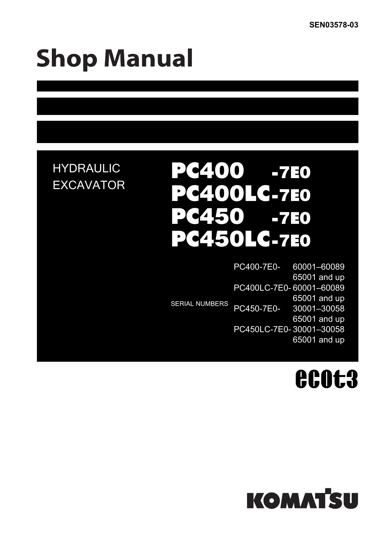
Komatsu PC400-7E0 PC400LC-7E0 PC450-7E0 PC450LC-7E0 Excavator Shop Manual PDF SEN03578-03 — PDF page 1 preview
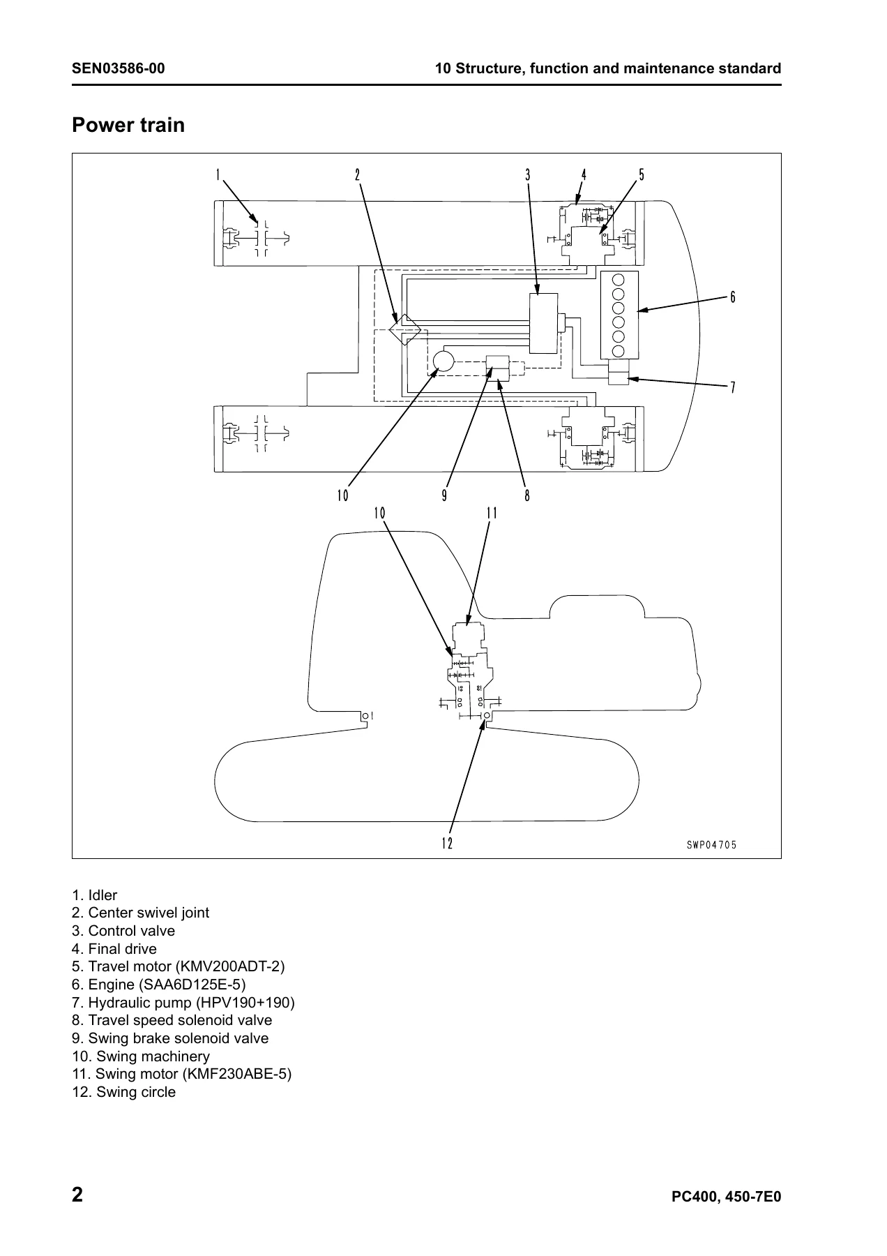
Komatsu PC400-7E0 PC400LC-7E0 PC450-7E0 PC450LC-7E0 Excavator Shop Manual PDF SEN03578-03 — PDF page 79 preview
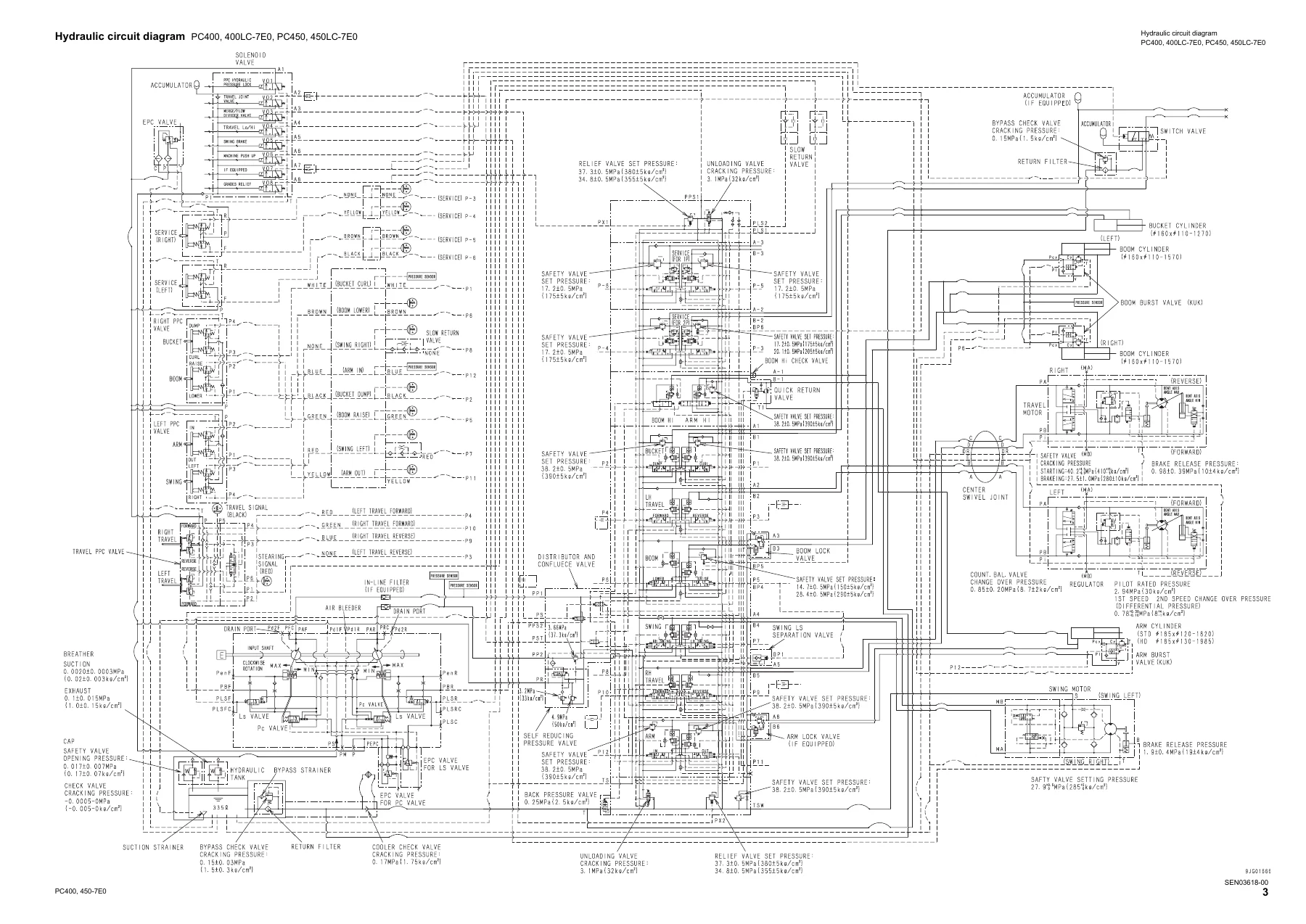
Komatsu PC400-7E0 PC400LC-7E0 PC450-7E0 PC450LC-7E0 Excavator Shop Manual PDF SEN03578-03 — PDF page 1016 preview

What This Komatsu PC400 / PC450-7E0 Excavator Shop Manual Enables

The Komatsu PC400-7E0, PC400LC-7E0, PC450-7E0 and PC450LC-7E0 shop manual (SEN03578-03) is aimed at the working technician, the fleet maintenance department, and the owner-operator who services their own machine. With it in hand you can look up the exact specification for a component before you touch it, understand what the hydraulic system is meant to do before you chase a symptom through it, follow a Komatsu failure code to the wiring harness, sensor, solenoid or controller that produced it, measure pressures and clearances against the standard value table, and disassemble and reassemble major components with the correct tools, torques and capacities. Because it covers the SAA6D125E-5 engine, the HPV160+160 pump pair, the CLSS control valve and the travel/swing motor assemblies in one place, the manual removes the guesswork that comes from working off a generic repair source.

Correct procedures and correct specifications matter on a machine of this size – a wrong torque on a swing circle or final drive bolt, a pump adjustment made without the specified test condition, or an incorrect relief pressure setting can all lead to premature failure, downtime and expensive parts. The hydraulic circuit diagrams, electrical circuit diagrams and connector lists in the 90 Diagrams and Drawings part of this Komatsu PC450-7E0 and PC400-7E0 shop manual let you trace wiring and hydraulic lines with confidence, which saves both time and diagnostic guesswork. This is a PDF manual delivered by instant download after purchase, so it can be used on a laptop, tablet or phone in the workshop, printed for the bench, or kept on a USB stick in the service truck – no shipping, no waiting, no physical copy to lose.


Reviews

There are no reviews yet.

Be the first to review “Komatsu PC400-7E0 PC400LC-7E0 PC450-7E0 PC450LC-7E0 Excavator Shop Manual PDF SEN03578-03”

What Our Customers Say

★★★★★ Live reviews from customers
Loading customer reviews...
0
    0
    Your Cart
    Your cart is emptyReturn to Shop
    🛒
    Recently Purchased
    🕒 verified order