
Trusted Business
Verified & Licensed
Virus Free Files
100% Safe Downloads
Secure Payment
SSL Protected
Instant Delivery
Available Immediately
Sale!


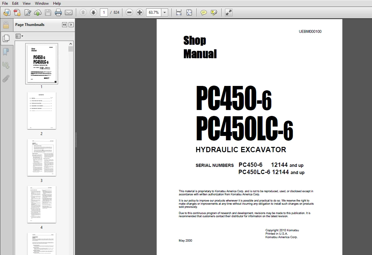
KOMATSU PC450- 6 PC450LC-6 HYDRAULIC EXCAVATOR SERVICE REPAIR MANUAL (UEBM000100) – PDF DOWNLOAD
Original price was: $86.95.$26.95Current price is: $26.95.
- KOMATSU PC450- 6 PC450LC-6 HYDRAULIC EXCAVATOR SERVICE REPAIR MANUAL
- PUBLICATION NUMBER:UEBM000100
- SERIAL NUMBER:PC450-6 12144 and up
PC450LC-6 12144 and up
Instant PDF Download
Available immediately
Save to Your Device
Download & keep forever
Antivirus Scanned
100% virus-free
Trusted Worldwide
175,000+ customers
Description
KOMATSU PC450- 6 PC450LC-6 HYDRAULIC EXCAVATOR SERVICE REPAIR MANUAL (UEBM000100)
KOMATSU PC450- 6 PC450LC-6 HYDRAULIC EXCAVATOR SERVICE REPAIR MANUAL (UEBM000100) – PDF DOWNLOAD:
IMAGE PREVIEW:
DESCRIPTION:
KOMATSU PC450- 6 PC450LC-6 HYDRAULIC EXCAVATOR SERVICE REPAIR MANUAL (UEBM000100)
- This shop manual has been prepared as an aid to improve the quality of repairs by giving the servicemen an accurate understanding of the product and by showing him the correct way to perform repairs and make judgements. Make sure you understand the contents of this manual and use it to full effect at every opportunity.
- This shop manual mainly contains the necessary technical information for operations performed in a service workshop. For ease of understanding, the manual is divided into the following chapters; these chapters are further divided into the each main group of components.
- STRUCTURE AND FUNCTION
This section explains the structure and function of each component. It serves not only to give an understanding of the structure, but also serves as reference material for troubleshooting. - TESTING AND ADJUSTING
This section explains checks to be made before and after performing repairs, as well as adjustments to be made at completion of the checks and repairs. Troubleshooting charts correlating ”Problems“ to ”Causes” are also included in this section. - DISASSEMBLY AND ASSEMBLY
This section explains the order to be followed when removing, installing, disassembling or assembling each component, as well as precautions to be taken for these operations. - MAINTENANCE STANDARD
This section gives the judgement standards when inspecting disassembled parts.
TABLE OF CONTENTS:
KOMATSU PC450- 6 PC450LC-6 HYDRAULIC EXCAVATOR SERVICE REPAIR MANUAL (UEBM000100)
01 General........................................................................................................... 21
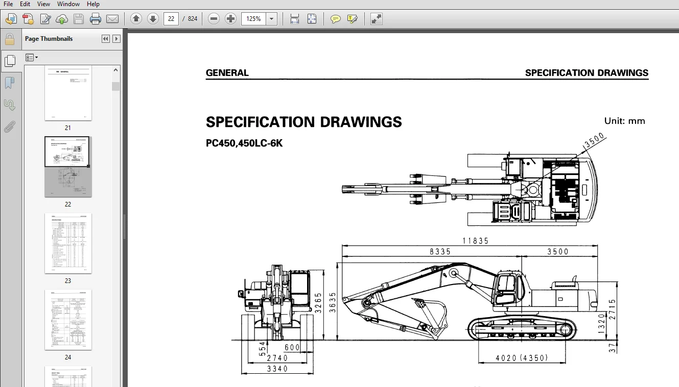
	Specification drawings........................................................................................... 22
	Specifications................................................................................................... 23
	Weight table..................................................................................................... 25
	Fuel, coolant and lubricants..................................................................................... 27
10 Structure and Function............................................................................................ 29
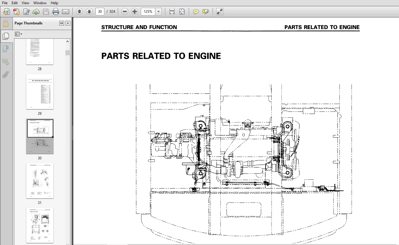
	Parts related to engine.......................................................................................... 30
	Radiator, oil cooler............................................................................................. 32
	Power train...................................................................................................... 33
	Final drive...................................................................................................... 34
	Swing circle..................................................................................................... 35
	Swing machinery.................................................................................................. 36
	Track frame, recoil spring....................................................................................... 37
	Track shoe....................................................................................................... 38
	Hydraulic piping drawing......................................................................................... 40
	Hydraulic circuit diagram........................................................................................ 42
	Hydraulic tank, hydraulic filter................................................................................. 43
	Hydraulic pump................................................................................................... 45
	Control valve.................................................................................................... 66
	Self-reducing pressure valve..................................................................................... 76
	Suction safety valve............................................................................................. 81
	CLSS............................................................................................................. 83
	Swing motor......................................................................................................148
	Center swivel joint..............................................................................................154
	Travel motor.....................................................................................................156
	Valve control....................................................................................................165
	Work equipment * swing PPC valve.................................................................................166
	Travel PPC valve.................................................................................................170
	Service PPC valve................................................................................................174
	PPC safety lock valve............................................................................................177
	PPC accumulator..................................................................................................177
	PPC shuttle valve, travel junction valve.........................................................................179
	LS-EPC valve.....................................................................................................186
	Solenoid valve...................................................................................................190
	Boom safety valve................................................................................................192
	Overload warning device..........................................................................................195
	Work equipment...................................................................................................197
	Air conditioner..................................................................................................198
	Actual electric wiring diagram...................................................................................199
	Electric circuit diagram.........................................................................................203
	Engine control...................................................................................................206
	Electronic control system........................................................................................213
	Machine monitor system...........................................................................................240
	Breaker mode hydraulic performance...............................................................................251
20 Testing and Adjusting.............................................................................................253
	Standard value table.............................................................................................254
		Standard value table for engine related parts................................................................254
		Standard value table for chassis related parts...............................................................255
		Standard value table for electrical parts....................................................................263
	Testing and adjusting............................................................................................271
		Tools for testing, adjusting, and troubleshooting............................................................272
		Measuring engine speed.......................................................................................273
		Measuring exhaust color......................................................................................274
		Adjusting valve clearance....................................................................................275
		Measuring compression pressure...............................................................................276
		Measuring blow-by pressure...................................................................................276
		Testing and adjusting fuel injection timing..................................................................277
		Measuring engine oil pressure................................................................................279
		Testing and adjusting fan belt tension.......................................................................280
		Testing and adjusting belt tension for air conditioner compressor............................................280
		Adjusting engine speed sensor................................................................................281
		Measuring air supply pressure (boost pressure)...............................................................282
		Testing and adjusting governor motor lever stroke............................................................283
		Testing and adjusting hydraulic pressure in work equipment, swing, travel circuit............................284
		Testing and adjusting TVC valve output pressure (servo piston input pressure)................................287
		Testing and adjusting LS valve output pressure (servo piston input pressure) and LS differential pressure....289
		Testing control circuit oil pressure (oil pressure when self-pressure is reduced)............................292
		Testing solenoid valve output pressure.......................................................................293
		Measuring PPC valve output pressure and testing PPC shuttle valve............................................296
		Adjusting work equipment, swing PPC valve....................................................................298
		Testing travel deviation.....................................................................................299
		Testing locations causing hydraulic drift of work equipment..................................................300
		Measuring oil leakage........................................................................................302
		Releasing remaining pressure in hydraulic circuit............................................................304
		Testing clearance of swing circle bearing....................................................................305
		Testing wear of sprocket.....................................................................................306
		Testing and adjusting track shoe tension.....................................................................307
		Bleeding air.................................................................................................308
	Troubleshooting..................................................................................................311
		Points to remember when troubleshooting......................................................................312
		Sequence of events in troubleshooting........................................................................313
		Points to remember when carrying out maintenance.............................................................314
		Checks before troubleshooting................................................................................322
		Connector types and mounting locations.......................................................................324
		Connector arrangement diagram................................................................................326
		Connection table for connector pin numbers...................................................................329
		Explanation of control mechanism of electrical system........................................................339
		Display method of special functions of monitor panel.........................................................340
		Method of using judgement table..............................................................................349
		Method of using troubleshooting charts.......................................................................351
		Details of troubleshooting and troubleshooting procedure.....................................................353
		Service code table...........................................................................................358
		Troubleshooting of communication abnormality system (N mode).................................................359
		Troubleshooting of governor, pump controller (governor control system) (E mode)..............................363
		Troubleshooting of engine system (S mode)....................................................................395
		Troubleshooting of governor, pump controller (pump control system) (C mode)..................................419
		Troubleshooting of governor, pump controller (input signal system) (F mode)..................................467
		Troubleshooting of hydraulic, mechanical system (H mode).....................................................481
		Troubleshooting of machine monitor system (M mode)...........................................................517
30 Disassembly and Assembly..........................................................................................563
	Method of using manual...........................................................................................565
	Precautions when carrying out operation..........................................................................567
	Special tool list................................................................................................569
40 Maintenance Standard..............................................................................................769
90 Others............................................................................................................817
PLEASE NOTE:
⦁ This is not a physical manual but a digital manual – meaning no physical copy will be couriered to you. The manual can be yours in the next 2 mins as once you make the payment, you will be directed to the download page IMMEDIATELY.
⦁ This is the same manual used by the dealers inorder to diagnose your vehicle of its faults.
⦁ Require some other service manual or have any queries: please WRITE to us at [email protected]




Brody J –