★ TRUSTED BY 321,897+ PROFESSIONALS WORLDWIDE
🏒
Trusted Business
Verified & Licensed
πŸ›‘οΈ
Virus Free Files
100% Safe Downloads
πŸ”’
Secure Payment
SSL Protected
⚑
Instant Delivery
Available Immediately
Sale!

Komatsu PC450-7K PC450LC-7K PC450LCHD-7K Excavator Operation and Maintenance Manual – PDF

Original price was: $44.95.Current price is: $26.95.

Complete Komatsu PC450-7K, PC450LC-7K and PC450LCHD-7K hydraulic excavator operation and maintenance manual for serial numbers K40001 and up. Covers safety, operation, maintenance schedules, specifications, attachments and 25m high reach demolition equipment in a single 404-page PDF.

⚑
Instant PDF Download
Available immediately
πŸ’Ύ
Save to Your Device
Download & keep forever
πŸ›‘οΈ
Antivirus Scanned
100% virus-free
🌍
Trusted Worldwide
175,000+ customers

Description

Komatsu PC450-7K / PC450LC-7K / PC450LCHD-7K Operation and Maintenance Manual

This is the full operation and maintenance manual for the Komatsu PC450-7K, PC450LC-7K and PC450LCHD-7K hydraulic excavators, covering machines from serial number K40001 and up. It is the same document Komatsu issued with these Galeo-series machines (Form No. UEAM003102), supplied here as an instant-download PDF. Everything a working owner, operator or maintenance technician needs to run, service and repair the 450-class excavator is contained in one searchable, printable file.

File Details

  • Manual type: Operation and Maintenance Manual
  • Brand: Komatsu
  • Models covered: PC450-7K, PC450LC-7K, PC450LCHD-7K
  • Serial number range: PC450-7K, PC450LC-7K, PC450LCHD-7K – K40001 and up
  • Language: English
  • Page count: 404 pages
  • File format: PDF
  • Document number: UEAM003102
  • Publication date: 10-05 (October 2005)
  • Publisher: Komatsu

Chapters Covered

The contents are broken into the standard Komatsu manual structure, with the high reach demolition section added as a dedicated chapter:

  • Foreword & Safety Information – signal words, safety labels, safety machine operation, battery, towing, lifting objects with the bucket, safety maintenance information
  • Noise & Vibration – sound pressure level (76 dB LpA), sound power level (107 dB LWA), hand-arm and whole-body vibration values
  • Introduction – directions of machine, breaking-in the new machine, product information, machine and engine serial number plates, service meter location, locking
  • Safety – location of safety labels, safety labels, safety machine operation, starting engine, operation, transportation, battery, towing, lifting, safety maintenance information
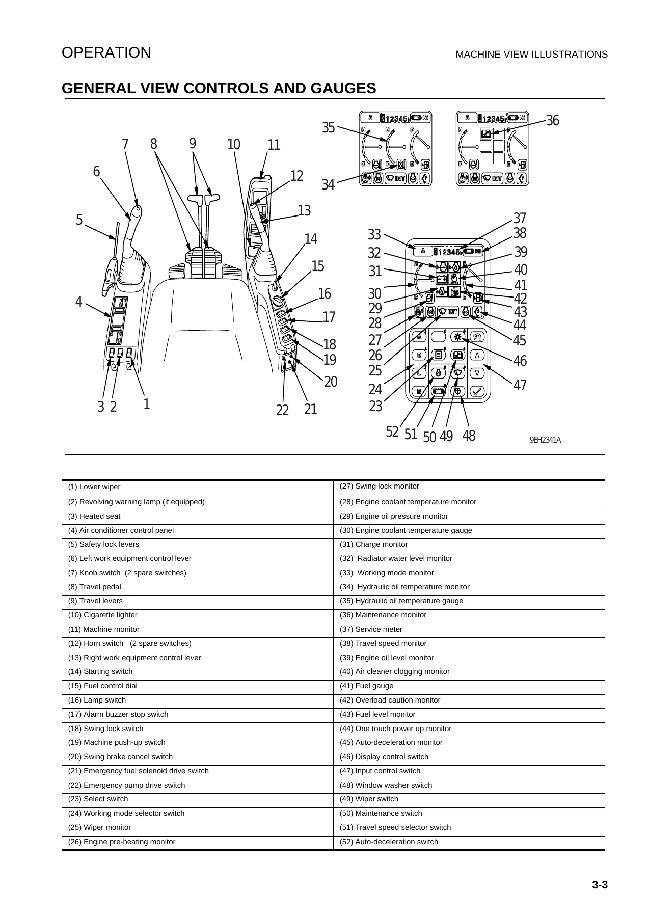
  • Operation – machine view illustrations, controls and gauges, machine monitor, switches, control levers and pedals, sun roof, windshield, emergency exit, door lock, cap with lock, hot and cool box, air conditioner controls, auxiliary electric power, fuse and fusible link, tool box, grease gun holder, refuelling pump, controllers, accumulator
  • Machine Operations and Controls – before starting engine, starting engine (normal and cold weather), warming-up, stopping the engine, moving the machine, steering, swinging, work equipment controls, working modes, prohibited operations, traveling on slopes, escape from mud, recommended applications, bucket replacement and inversion, parking, transportation, cold weather operation, long-term storage, troubles and actions
  • Maintenance – maintenance information, lubricants/coolant/filters, wear parts, lubricants/fuel/coolant specifications, tightening torque list, safety critical parts, maintenance schedule, maintenance procedure (initial 250 and 1000 hours, when required, every 250, 500, 1000, 2000, 4000, 5000, 8000 hours)
  • Specifications – operating weights, dimensions, engine rating, travel and swing speeds, working ranges, lifting capacity charts for the PC450-7K, PC450LC-7K and PC450LCHD-7K
  • Attachments and Options – general precautions, machine ready for attachment, hydraulic circuit, attachment removal and installation, attachment operations, long-term storage, attachment guide, shoe and tooth selection, recommended attachment operations (hydraulic breaker)
  • High Reach Work Equipment (25m) – general view, control levers and switches, safety lock, travel levers, work equipment control levers, crusher pedals, tilting cab, boom angle alarm, ceiling wiper, demolition/standard changeover switch, machine operations and controls, working range of boom, demolition digging boom installation and removal, purging air procedures, transportation, specifications
  • Index

What this document gives a technician is a complete operational and service reference for the 450-class Galeo excavator family, not just an operator primer. It combines the day-to-day running instructions an operator needs – start-up, warm-up, working modes, travel and swing, safe loading – with the full periodic maintenance schedule that a workshop or fleet owner follows: what to grease every 250 hours, when the engine oil and filter should be changed, how to adjust track tension, how to bleed the hydraulic system, how to clean or replace air cleaner elements, when to replace safety-critical hoses and seat belts, and how to troubleshoot the electronic control system. The high reach chapter adds the 25m demolition configuration, including the intermediate link, crusher control pedals, tilting cab mechanism and the pin-retract procedure for swapping between high reach and digging equipment.

What You Can Do With This Komatsu PC450-7K Manual

Because this is the Komatsu PC450-7K operation and maintenance manual in its full 404-page form, it supports real jobs rather than just reading. Owners of a PC450LC-7K can use it to confirm the correct engine oil viscosity for the ambient temperature, find the 650-litre fuel tank capacity, check the 76 dB operator noise level, or look up which fuses protect the air conditioner and monitor circuits. Workshop technicians servicing a PC450LCHD-7K high reach machine can follow the boom lock valve air-purging procedure, the pin retract sequence for removing the demolition boom, and the lifting capacity charts for both straight and bent positions. Fleet managers can print the maintenance schedule chart and use it as the backbone of a scheduled service programme for K40001-and-up machines.

Having the exact values from the manual rather than a generic guess matters on a machine of this size. The wrong grease interval, an incorrect track tension figure, or an improvised accumulator procedure on a 45-tonne excavator can turn a routine service into a major failure. This manual gives the specified torques, capacities, pressures and step-by-step procedures as Komatsu wrote them for these serial numbers.

Complete PDF Bookmark Tree

Complete Bookmarks

The complete bookmarks in the β€œKomatsu PC450-7K PC450LC-7K PC450LCHD-7K Excavator Operation and Maintenance Manual – PDF” are as follows:

FOREWORDp. 3
FOREWORDp. 4
SAFETY INFORMATIONp. 5
NOISEp. 7
VIBRATIONp. 7
INTRODUCTIONp. 8
DIRECTIONS OF MACHINEp. 8
BREAKING-IN THE NEW MACHINEp. 8
PRODUCT INFORMATIONp. 9
MACHINE SERIAL NUMBER PLATE AND ITS LOCATIONp. 9
ENGINE SERIAL NUMBER PLATE AND ITS LOCATIONp. 9
SERVICE METER LOCATIONp. 10
YOUR MACHINE SERIAL NUMBERS AND DISTRIBUTORp. 10
MACHINE SERIAL PLATEp. 11
FOREWORDp. 12
SAFETYp. 12
OPERATIONp. 12
MAINTENANCEp. 15
SPECIFICATIONSp. 17
ATTACHMENTS AND OPTIONSp. 17
HIGH REACH WORK EQUIPMENT (25m)p. 18
INDEXp. 19
COLOPHONp. 19
SAFETYp. 21
SAFETY INFORMATIONp. 22
SAFETY LABELSp. 24
LOCATION OF SAFETY LABELSp. 24
SAFETY LABELSp. 25
SAFETY INFORMATIONp. 32
SAFETY MACHINE OPERATIONp. 41
STARTING ENGINEp. 41
OPERATIONp. 43
TRANSPORTATIONp. 49
BATTERYp. 50
TOWINGp. 52
LIFTING OBJECTS WITH BUCKETp. 53
SAFETY MAINTENANCE INFORMATIONp. 54
OPERATIONp. 61
MACHINE VIEW ILLUSTRATIONSp. 62
OVERALL MACHINE VIEWp. 62
GENERAL VIEW CONTROLS AND GAUGESp. 63
EXPLANATION OF COMPONENTSp. 64
MACHINE MONITORp. 64
Basic Operation Of Machine Monitorp. 65
Basic Check Monitorsp. 67
Caution Monitorsp. 69
Emergency Monitorsp. 72
Meter Display Portionp. 74
Monitor Switches Portionp. 79
SWITCHESp. 90
CONTROL LEVERS AND PEDALSp. 96
SUN ROOFp. 99
WINDSHIELDp. 99
EMERGENCY EXIT FROM OPERATOR'S CABp. 104
DOOR LOCKp. 104
CAP WITH LOCKp. 105
HOT AND COOL BOXp. 106
MAGAZINE BOXp. 107
ASHTRAYp. 107
AIR CONDITIONER CONTROLSp. 108
Air Conditioner Control Panelp. 108
Method Of Operationp. 113
Use Air Conditioner With Carep. 119
Inspection and maintenance of air conditioner equipped machinep. 119
Other Functionsp. 120
Use Radio With Carep. 121
AUXILIARY ELECTRIC POWERp. 122
24V power sourcep. 122
12V power sourcep. 122
FUSEp. 123
FUSIBLELINKp. 124
TOOL BOXp. 125
GREASE GUN HOLDERp. 125
REFUELLING PUMPp. 126
CONTROLLERSp. 127
TOOL BOXp. 128
GREASE GUN HOLDERp. 128
ACCUMULATORp. 129
Releasing Hydraulic Pressure With Accumulatorp. 129
MACHINE OPERATIONS AND CONTROLSp. 130
BEFORE STARTING ENGINEp. 130
Walk-Around Checksp. 130
Checks Before Startingp. 131
Adjustmentp. 137
Seat Beltp. 140
Operations Before Starting Enginep. 141
STARTING ENGINEp. 144
Normal Startingp. 144
Starting Engine In Cold Weatherp. 146
AFTER STARTING ENGINEp. 148
Warming-Up Operationp. 148
In Cold Weather Areasp. 152
STOPPING THE ENGINEp. 157
MACHINE OPERATIONp. 158
Preparations For Moving The Machine Offp. 158
Moving Machine Forwardp. 159
Moving Machine Backwardp. 160
Stopping Machinep. 161
STEERING THE MACHINEp. 162
Steeringp. 162
SWINGINGp. 164
WORK EQUIPMENT CONTROLS AND OPERATIONSp. 165
WORKING MODEp. 167
PROHIBITED OPERATIONSp. 168
GENERAL OPERATION INFORMATIONp. 170
TRAVELING ON SLOPESp. 171
ESCAPE FROM MUDp. 173
Stuck One Side Of Trackp. 173
Stuck Both Sides Of Tracksp. 173
RECOMMENDED APPLICATIONSp. 174
Backhoe Workp. 174
Shovel Workp. 174
Ditching Workp. 174
Loading Workp. 175
BUCKET REPLACEMENT AND INVERSIONp. 176
Replacementp. 176
Inversionp. 178
PARKING MACHINEp. 179
CHECK AFTER SHUT OFF ENGINEp. 180
MACHINE INSPECTION AFTER DAILY WORKp. 180
LOCKINGp. 181
TRANSPORTATIONp. 182
PRECAUTIONS FOR TRANSPORTATIONp. 182
LIFTING MACHINEp. 182
PRECAUTIONS WHEN LOADINGp. 183
TRANSPORTATION POSTUREp. 183
LOADING AND UNLOADING WITH TRAILERp. 187
LOADINGp. 188
SECURING MACHINEp. 190
UNLOADINGp. 192
PROCEDURE FOR INCREASING OR REDUCING TRACK FRAME GAUGEp. 194
COLD WEATHER OPERATIONp. 196
COLD WEATHER OPERATION INFORMATIONp. 196
Fuel And Lubricantsp. 196
Cooling System Coolantp. 196
Batteryp. 197
AFTER DAILY WORK COMPLETIONp. 198
AFTER COLD WEATHER SEASONp. 198
LONG TERM STORAGEp. 199
BEFORE STORAGEp. 199
DURING STORAGEp. 199
AFTER STORAGEp. 200
STARTING MACHINE AFTER LONG-TERM STORAGEp. 200
TROUBLES AND ACTIONSp. 201
RUNNING OUT OF FUELp. 201
PHENOMENA THAT ARE NOT FAILURESp. 202
TOWING THE MACHINEp. 203
LIGHTWEIGHT TOWING HOLEp. 204
SEVERE JOB CONDITIONp. 204
DISCHARGED BATTERYp. 205
Battery Removal And Installationp. 205
Battery Chargesp. 206
Starting Engine With Booster Cablesp. 207
OTHER TROUBLEp. 209
Electrical Systemp. 209
Chassisp. 210
Enginep. 211
Electronic Control Systemp. 213
Point Of Contact To Telephone When Error Occursp. 214
MAINTENANCEp. 215
MAINTENANCE INFORMATIONp. 216
LUBRICANTS, COOLANT AND FILTERSp. 218
HANDLING OIL, FUEL, COOLANT, AND PERFORMING OIL CLINICp. 218
Oilp. 218
Fuelp. 218
Cooling System Coolantp. 219
Greasep. 219
Carrying out KOWA (Komatsu Oil Wear Analysis)p. 220
Oil And Fuel Storagep. 221
Filtersp. 221
ELECTRIC SYSTEM MAINTENANCEp. 221
EXPLANATION OF LUBRICATION CHART DECALp. 222
WEAR PARTSp. 224
WEAR PARTS LISTp. 224
LUBRICANTS, FUEL AND COOLANT SPECIFICATIONSp. 225
TIGHTENING TORQUE SPECIFICATIONSp. 229
TIGHTENING TORQUE LISTp. 229
SAFETY CRITICAL PARTSp. 230
SAFETY CRITICAL PARTS LISTp. 230
MAINTENANCE SCHEDULEp. 231
MAINTENANCE SCHEDULE CHARTp. 231
MAINTENANCE INTERVAL FOR HYDRAULIC BREAKERp. 233
MAINTENANCE PROCEDUREp. 234
INITIAL 250 HOURS MAINTENANCE (ONLY AFTER THE FIRST 250 HOURS)p. 234
INITIAL 1000 HOURS MAINTENANCE (ONLY AFTER THE FIRST 1000 HOURS)p. 234
WHEN REQUIREDp. 235
CHECK, CLEAN AND REPLACE AIR CLEANER ELEMENTp. 235
CLEAN INSIDE OF COOLING SYSTEMp. 240
CHECK AND TIGHTEN TRACK SHOE BOLTSp. 243
CHECK AND ADJUST TRACK TENSIONp. 244
CHECK ELECTRICAL INTAKE AIR HEATERp. 245
REPLACE BUCKET TEETH (VERTICAL PIN TYPE)p. 246
REPLACE BUCKET TEETH (HORIZONTAL PIN TYPE)p. 249
REPLACE BUCKET SIDE CUTTER, SHROUDp. 250
ADJUST BUCKET CLEARANCEp. 251
CHECK WINDOW WASHER FLUID LEVEL, ADD FLUIDp. 252
CHECK AND ADJUST AIR CONDITIONERp. 253
WASH WASHABLE FLOORp. 254
BLEEDING AIR FROM HYDRAULIC SYSTEMp. 258
METHOD FOR RELEASING INTERNAL PRESSURE IN HYDRAULIC CIRCUITp. 261
CHECK NITROGEN GAS CHARGE PRESSURE IN ACCUMULATOR (control circuit)p. 262
CHECK BEFORE STARTINGp. 263
EVERY 250 HOURS MAINTENANCEp. 264
LUBRICATINGp. 264
CHECK OIL LEVEL IN SWING MACHINERY CASE, ADD OILp. 265
CHECK OIL LEVEL IN FINAL DRIVE CASE, ADD OILp. 266
CHECK LEVEL OF BATTERY ELECTROLYTEp. 267
LUBRICATE SWING CIRCLEp. 270
CHECK FAN BELT, ALTERNATOR BELT TENSION, ADJUSTp. 270
CHECK AIR CONDITIONER COMPRESSOR BELT TENSION, ADJUSTp. 272
EVERY 500 HOURS MAINTENANCEp. 273
LUBRICATINGp. 273
REPLACE FUEL FILTER CARTRIDGEp. 275
CHECK, WASH FUEL STRAINERp. 277
CHECK SWING PINION GREASE LEVEL, ADD GREASEp. 278
CHANGE OIL IN ENGINE OIL PAN, REPLACE ENGINE OIL FILTER CARTRIDGEp. 279
CLEAN AND INSPECT RADIATOR FINS, OIL COOLER FINS, AFTER COOLER FINS, FUEL COOLER FINS, AND CONDENSER FINS (ONLY MACHINES EQUIPPED WITH AIR CONDITIONER)p. 281
CLEAN AIR CONDITIONER FRESH/RECIRC FILTERSp. 282
REPLACE BREATHER ELEMENT IN HYDRAULIC TANKp. 283
REPLACE ADDITIONAL FUEL FILTER CARTRIDGEp. 284
EVERY 1000 HOURS MAINTENANCEp. 286
REPLACE HYDRAULIC OIL FILTER ELEMENTp. 286
CHANGE OIL IN SWING MACHINERY CASEp. 288
CHECK OIL LEVEL IN DAMPER CASE, ADD OILp. 289
CHECK ALL TIGHTENING PARTS OF TURBOCHARGERp. 289
CHECK PLAY TURBOCHARGER ROTORp. 289
REPLACE CORROSION RESISTOR CARTRIDGEp. 290
REPLACE HYDRAULIC TANK ADDITIONAL BREATHER ELEMENTp. 291
CHECK NITROGEN GAS CHARGE PRESSURE IN ACCUMULATOR (for breaker)p. 291
EVERY 2000 HOURS MAINTENANCEp. 292
CHANGE OIL IN FINAL DRIVE CASEp. 292
CHECK INJECTORp. 292
CLEAN HYDRAULIC TANK STRAINERp. 293
CLEAN ENGINE BREATHERp. 293
CLEAN, CHECK TURBOCHARGERp. 294
CHECK ALTERNATOR, STARTING MOTORp. 294
CHECK ENGINE VALVE CLEARANCE, ADJUSTp. 294
CHECK VIBRATION DAMPERp. 294
EVERY 4000 HOURS MAINTENENCEp. 295
CHECK WATER PUMPp. 295
CHECK FOR LOOSENESS OF HIGH-PRESSURE CLAMP, HARDENING OF RUBBERp. 295
CHECK FOR MISSING FUEL SPRAY PREVENTION CAP, HARDENING OF RUBBERp. 296
REPLACE INJECTOR NOZZLE ASSEMBLYp. 296
EVERY 5000 HOURS MAINTENANCEp. 297
CHANGE OIL IN HYDRAULIC TANKp. 297
EVERY 8000 HOURS MAINTENANCEp. 299
REPLACE HIGH-PRESSURE PIPING CLAMPp. 299
REPLACE FUEL SPRAY PREVENTION CAPp. 299
SPECIFICATIONSp. 301
SPECIFICATIONSp. 302
ATTACHMENTS AND OPTIONSp. 313
GENERAL PRECAUTIONS FOR SAFETYp. 314
PRECAUTIONS WHEN SELECTINGp. 314
READ THE INSTRUCTION MANUAL THOROUGHLYp. 314
PRECAUTIONS WHEN REMOVING OR INSTALLINGp. 314
PRECAUTIONS WHEN USINGp. 315
MACHINE READY FOR ATTACHMENTp. 316
LOCATIONSp. 316
HYDRAULIC CIRCUITp. 320
Switching Hydraulic Circuitp. 320
Adjusting Oil Flowp. 320
Switching Between Breaker and General Attachmentp. 320
Hydraulic Circuit Connectionp. 321
Oil Flow Pathp. 322
Replace Additional Breaker Filter Elementp. 323
ATTACHMENT REMOVAL AND INSTALLATIONp. 324
Attachment Removalp. 324
Attachment Installationp. 325
ATTACHMENT OPERATIONSp. 326
When Using Breakerp. 326
When Using General Attachment Such As Crusherp. 327
LONG TERM STORAGEp. 328
SPECIFICATIONSp. 328
ATTACHMENT GUIDEp. 329
ATTACHMENT COMBINATIONSp. 329
METHOD OF SELECTING SHOESp. 331
SELECTION OF BUCKET TEETHp. 332
METHOD OF SELECTING TEETHp. 332
STANDARDS FOR SELECTING VERTICAL PIN TYPE AND HORIZONTAL PIN TYPE TEETHp. 332
RECOMMENDED ATTACHMENT OPERATIONSp. 333
HYDRAULIC BREAKERp. 333
HIGH REACH WORK EQUIPMENT (25m)p. 339
GENERAL VIEWp. 340
GENERAL VIEW OF MACHINEp. 340
CAUTION ITEMSp. 341
CONTROL LEVERS AND SWITCHESp. 342
SAFETY LOCK LEVERp. 342
TRAVEL LEVERSp. 343
WORK EQUIPMENT CONTROL LEVERSp. 344
CRUSHER CONTROL PEDAL FOR OPENING AND CLOSINGp. 345
INTERMEDIATE LINK AND CRUSHER ROTATION CONTROL PEDAL Intermediate Link control (with auto-deceleration)p. 346
TILTING CAB MECHANISM OPERATIONp. 348
BOOM ANGLE ALARM BUZZER CANCEL SWITCHp. 349
CEILING WINDOW WIPER SWITCH (10)p. 350
DEMOLITION/STANDARD EQUIPMENT CHANGEOVER SWITCH (11)p. 351
MACHINE OPERATIONS AND CONTROLSp. 352
BEFORE STARTING ENGINEp. 352
FUNCTION CHECKp. 353
PRECAUTIONS WHEN OPERATINGp. 353
PROHIBITON OF WORK IN THE OVER SIDES DIRECTIONp. 354
PROHIBITON OF WORK OUTSIDE SPECIFIED WORKING RANGEp. 354
PROHIBITION OF WORK AT THE STROKE END OF A CYLINDERp. 358
PROHIBITION OF WORK WITH HYDRAULIC BREAKERp. 358
OPERATIONp. 359
Adjustment of hydraulic variable gauge undercarriage, where fitted.p. 359
Operating work equipmentp. 360
Attachment controlp. 361
RAISING WORK EQUIPMENTp. 362
WORKING RANGE AND USING RANGE OF BOOMp. 363
POSTURE WHEN LEAVING MACHINEp. 367
DEMOLITION DIGGING BOOM INSTALLATION AND REMOVALp. 368
PROCEDURE FOR INSTALLATION AND REMOVAL OF DEMOLITION DIGGING EQUIPMENT.p. 368
REMOVAL OF HIGH REACH WORK EQUIPMENTp. 368
FITTING DEMOLITION DIGGING EQUIPMENT.p. 372
REMOVAL OF DEMOLITION DIGGING EQUIPMENT.p. 376
CONNECTING DIGGING ARM TO DEMOLITION DIGGING BOOMp. 376
PURGING AIR PROCEDURESp. 378
PURGING PROCEDURE TO REMOVE AIR FROM HYDRAULIC CYLINDER LINES.p. 378
PROCEDURE FOR PURGING AIR FROM BOOM LOCK VALVE PPC CIRCUITp. 378
PURGING AIR FROM HYDRAULIC DRIFT PREVENTATIVE VALVE PPC CIRCUITS OF MID LINK AND ARM CYLINDER.p. 380
TRANSPORTATION (high reach demolition equipment fitted)p. 381
PROCEDURE FOR LOADING ON TO TRAILERp. 381
TRANSPORTATION (demolition digging equipment fitted)p. 383
PROCEDURE FOR LOADING ON TO TRAILERp. 383
TRANSPORTATION (high reach demolition equipment alone)p. 383
PROCEDURE FOR LOADING ON TO TRAILERp. 383
SPECIFICATIONSp. 388
WORKING RANGE (PC 450LCD HIGH REACH)p. 388
WORKING RANGE (PC 450LCD MEDIUM REACH)p. 389
WORKING RANGE (PC 450LCD LOW REACH)p. 390
WORKING RANGE (PC 450LCD DIGGING)p. 391
WEIGHTS AND DIMENSIONSp. 392
TRANSPORTATION (High and Medium Reach work equipment) – PC450LCDp. 393
TRANSPORTATION (Digging equipment) – PC450LCDp. 394
EXPLANATION OF LIFTING CAPACITY CHARTp. 395
Demolition Dig Boom – Straight Positionp. 396
Demolition Dig Boom – Bent Positionp. 397
INDEXp. 399
COLOPHONp. 403


IMAGES PREVIEW

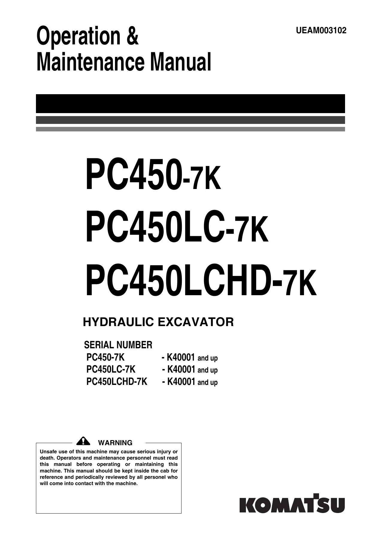
Komatsu PC450-7K PC450LC-7K PC450LCHD-7K Excavator Operation and Maintenance Manual - PDF β€” PDF page 1 preview
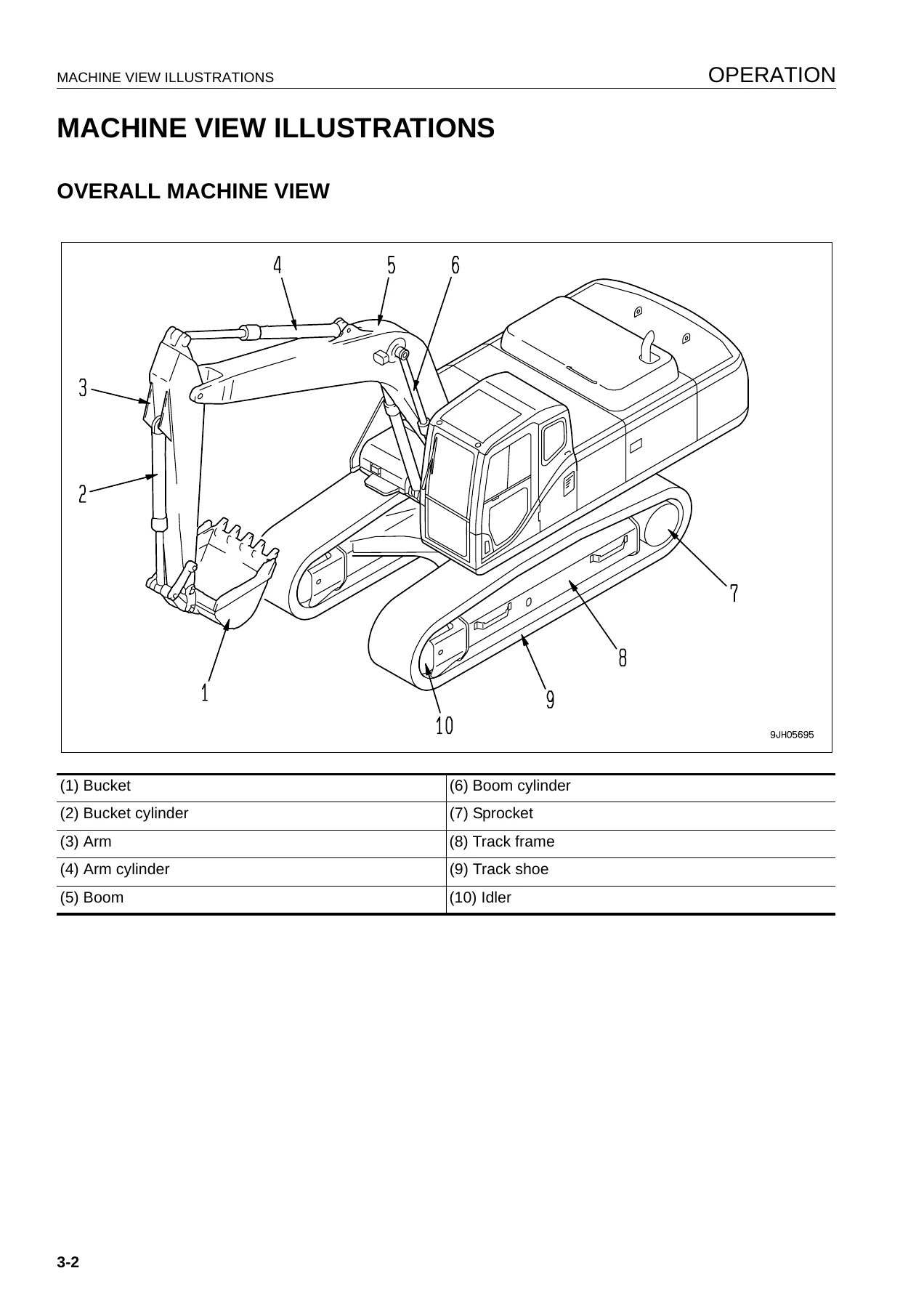
Komatsu PC450-7K PC450LC-7K PC450LCHD-7K Excavator Operation and Maintenance Manual - PDF β€” PDF page 62 preview
Komatsu PC450-7K PC450LC-7K PC450LCHD-7K Excavator Operation and Maintenance Manual - PDF β€” PDF page 63 preview

Instant PDF Delivery

The PC450-7K / PC450LC-7K / PC450LCHD-7K manual is delivered as an immediate PDF download once payment is complete. There is no shipping, no waiting for a disc or binder, and no risk of a damaged print copy. The file opens on any Windows PC, Mac, tablet or smartphone with a PDF reader, and every page can be printed for use in the workshop or cab. Whether you are diagnosing an E02 pump control error on the machine monitor, setting the working mode for a hydraulic breaker, or simply looking up the correct coolant mixture for winter, the answer is in this file.
Reviews

There are no reviews yet.

Be the first to review “Komatsu PC450-7K PC450LC-7K PC450LCHD-7K Excavator Operation and Maintenance Manual – PDF”

What Our Customers Say

β˜…β˜…β˜…β˜…β˜… Live reviews from customers
Loading customer reviews...
0
    0
    Your Cart
    Your cart is emptyReturn to Shop
    πŸ›’
    Recently Purchased
    πŸ•’ verified order