
Komatsu PC490LC-11 Hydraulic Excavator Field Assembly Manual GEN00126-07 – PDF Download
Original price was: $52.95.$34.95Current price is: $34.95.
Complete field assembly instructions for the Komatsu PC490LC-11 hydraulic excavator. Covers chassis assembly, work equipment installation, track frame gauge adjustment, counterweight mounting, hydraulic circuit flushing, KomVision camera calibration, torque tables and inspection reports. Document GEN00126-07, 157 pages, English.
Description
Komatsu PC490LC-11 Hydraulic Excavator — Field Assembly Instructions (GEN00126-07)
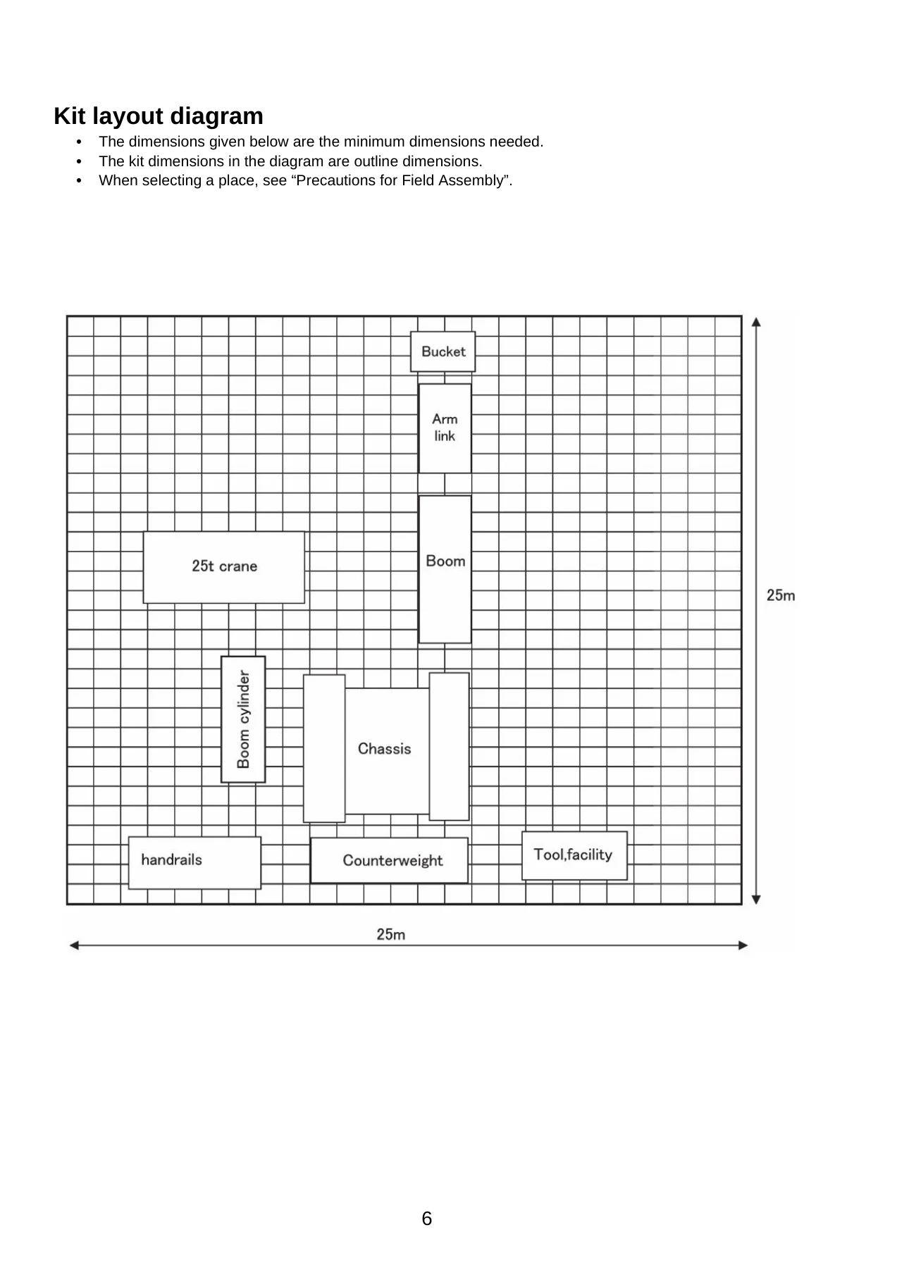
Because the PC490LC-11 is a large machine, Komatsu ships it from the factory in separate units to satisfy transportation conditions and regulations. This field assembly manual — document number GEN00126-07 — explains exactly how to assemble those units into the complete excavator at the worksite. It is the reference Komatsu expects the work supervisor, work leader, crane director, mechanics and operators to read before starting, and it covers every stage from the safety meeting through final inspection.
This is not a generic overview. The manual walks through the real assembly sequence: installation of the boom cylinder, boom, arm and bucket, connection of the hydraulic hoses between chassis, boom and bucket cylinder, adjustment of the track frame gauge, mounting of the 9,570 kg counterweight, flushing of the hydraulic circuit, and adjustment of the KomVision camera angle. Torque values, shim thicknesses, clearance limits and sling selection tables are all included.
File Details
- Manual type: Field Assembly Instructions
- Brand: Komatsu
- Model: PC490LC-11
- Document number: GEN00126-07
- Language: English
- Page count: 157
- File format: PDF
Chapters Covered
- A. Assembly of chassis
- B. Assembling of work equipment
- C. Increasing and decreasing of track frame gauge, assembling of counterweight
- M. Procedure for inspection and maintenance after completion of assembly
- Mounting bolt torque check sheet
- Field assembly inspection report (Backhoe)
A. Assembly of Chassis
Covers installation of the climbing step, handrail, mirror, tail pipe and tail pipe cover on the revolving frame and track frame. Each procedure includes the loose-supply part numbers, quantities, necessary tools and torque values, with illustrations showing bolt positions and tightening sequences.
B. Assembling of Work Equipment
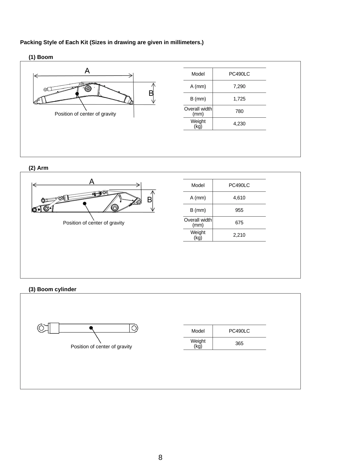
The largest section. Begins with installation of the boom cylinder foot pin and adjustment shims, then moves through releasing remaining pressure in the hydraulic circuit, connecting boom cylinder hoses, installing the boom cylinder top pin, slinging and installing the boom assembly (4,230 kg, or 4,950 kg with cylinder), connecting hoses along the top of the boom, installing the arm assembly (2,210 kg), bucket cylinder hoses, bucket installation (1,366 kg), grease piping, wiring for the optional LED lamp, greasing, and bleeding air from the work equipment circuit. Shim thickness options and clearance limits are given for every pin joint.
C. Increasing and Decreasing of Track Frame Gauge, Assembling of Counterweight
Covers the track frame gauge extension and retraction process, including the stopper bolt locations, center frame mounting bolt torque (1,520 to 1,910 Nm), and the sequence for raising and retracting the crawler frames. Also covers installation of steps, travel piping covers, track tension adjustment (standard slack 16 to 34 mm), sticking sheets to the revolving frame and counterweight, camera installation and adjustment, rear working lamp installation (optional LED), and installation of the counterweight (9,570 kg) with a mounting bolt torque of 3,430 to 4,212 Nm. Clearance and level difference tolerances between counterweight, revolving frame and exterior door are specified.
M. Procedure for Inspection and Maintenance After Completion of Assembly
Post-assembly procedures: replacement of the return filter with a flushing filter, flushing of the hydraulic circuit (work equipment, swing and travel circuits with specified durations), replacement of the flushing filter with the standard filter, checks of oil and coolant levels at each part, inspection of oil level in the hydraulic tank, touch-up of painted parts, KomVision camera angle adjustment (including camera calibration and 12 m visibility check), and error code verification. Fluid types and capacities for engine oil, hydraulic system, coolant, fuel and DEF are given, along with a coolant mixing proportion table by minimum temperature.
Torque Tables and Inspection Report
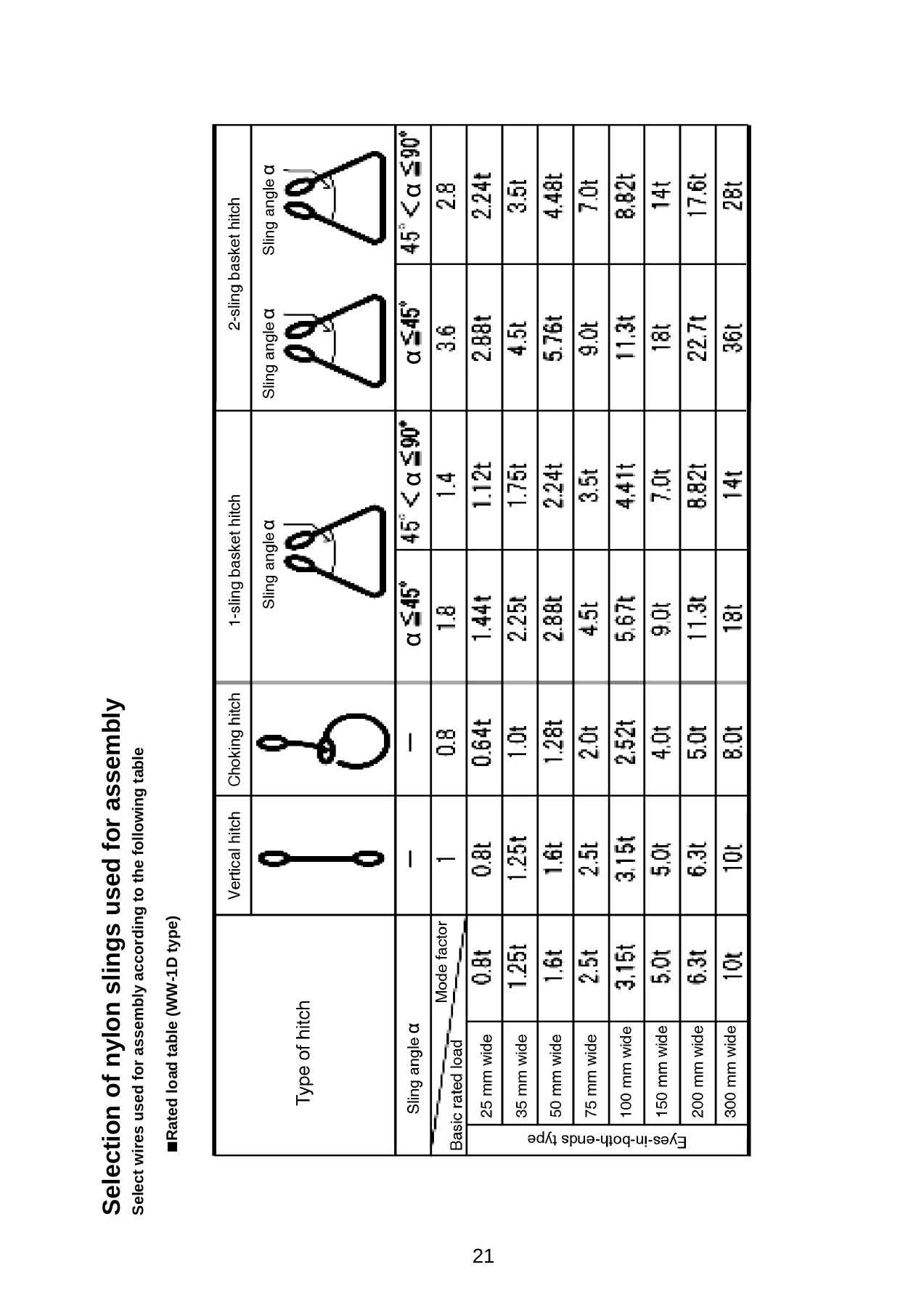
Includes a comprehensive tightening torque table for bolts not specified in text (M6 through M39), pipe thread tightening torque tables for mild steel, cast iron and refined steel, hydraulic hose connecting nut torque for face seal and taper seal types, socket sizes for M39 and larger bolts, a nylon sling selection table with rated loads by sling angle and hitch type, and a multi-page field assembly inspection report with judgement criteria.
Why This Manual Matters
Field assembly of a 47,040 kg excavator is not a job for guesswork. Incorrect shim selection, a missed torque value, or a hose connected with a twisted seal can cause pin galling, hydraulic leaks, or structural damage that shows up hundreds of hours later. This manual gives the exact figures: the 1.5 mm maximum clearance at the boom cylinder foot, the 1 mm maximum clearance at the boom foot and arm pins, the 0.5 to 1.5 mm clearance between cover and cylinder rod, the 3,820 Nm center value for counterweight bolts, and the 1,520 to 1,910 Nm for track frame bolts. It also provides the safety supervision structure — work supervisor, work leader, crane director, operator for assembly, mechanics, liaison man and interpreter — that Komatsu requires when workers of different languages and customs work together.
What You Can Do With It
Whether you are assembling a PC490LC-11 after transport, replacing a boom cylinder, adjusting track tension, installing a counterweight, flushing the hydraulic circuit, or calibrating the KomVision camera system, this manual provides the procedure, the torque, the tool list and the inspection criteria. The sling selection table lets you safely choose nylon slings by angle and hitch type for each component weight. The inspection report gives a structured checklist so nothing is missed before the machine goes to work.
IMAGES PREVIEW
Instant PDF Delivery
This Komatsu PC490LC-11 field assembly manual is delivered as an instant PDF download after payment. No shipping, no waiting. Open it on a laptop, tablet or phone at the worksite, or print the pages you need for the crew. The PDF preserves the original layout, illustrations and tables so the torque values, part numbers and diagrams stay readable in the field.


Reviews
There are no reviews yet.