
Komatsu PC500LC-10M0 Hydraulic Excavator Shop Manual SEN06813-06 – PDF Service & Repair Guide
Original price was: $59.95.$39.95Current price is: $39.95.
Complete Komatsu PC500LC-10M0 shop manual (SEN06813-06) covering engine, hydraulics, electrical, undercarriage, and troubleshooting for the SAA6D125E-5 powered excavator. Instant PDF download.
Description
Komatsu PC500LC-10M0 Shop Manual – SEN06813-06
This is the complete Komatsu PC500LC-10M0 hydraulic excavator shop manual, document number SEN06813-06. It covers the SAA6D125E-5 diesel engine and the full machine including hydraulic system, swing system, travel system, undercarriage, work equipment, cab, electrical system, and air conditioner. Every chapter is written for the technician who services, diagnoses, and repairs these machines.
File Details
- Manual type: Shop Manual
- Brand: Komatsu
- Model: PC500LC-10M0
- Engine: SAA6D125E-5
- Document number: SEN06813-06
- Language: English
- File format: PDF
- Page count: 1000+
Chapters Covered
- 00 Index and Foreword
- 01 Specifications
- 10 Structure and Function
- 20 Standard Value Table
- 30 Testing and Adjusting
- 40 Troubleshooting
- 50 Disassembly and Assembly
- 60 Maintenance Standard
- 80 Appendix (Air Conditioner)
- 90 Circuit Diagrams
00 Index and Foreword
This opening chapter contains the abbreviation list covering both text and circuit diagram terms, safety notices, fire prevention precautions, procedures for handling hydraulic equipment, electrical equipment, fuel systems, and intake systems. It also includes the standard tightening torque table and conversion table. Practical use of KOMTRAX is explained along with disconnection and connection procedures for push-pull type couplers, connectors, and various special lock connectors including Deutsch, slide lock, and lock-to-pull types.
01 Specifications
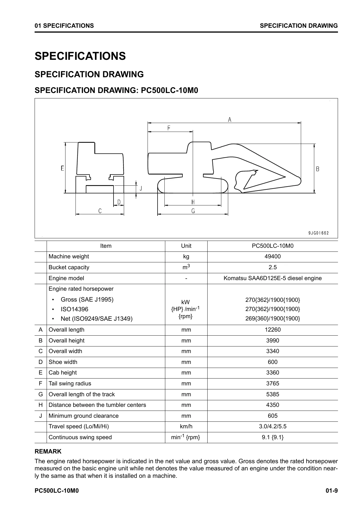
The specifications chapter provides the specification drawing for the PC500LC-10M0, working range drawings, weight tables, and the table of fuel, coolant, and lubricants. The engine rated horsepower is shown in both gross and net values. Dimensions including overall length, overall height, overall width, track length, and ground clearance are listed. The working range covers maximum digging reach, maximum digging depth, maximum digging height, and maximum dumping height.
10 Structure and Function
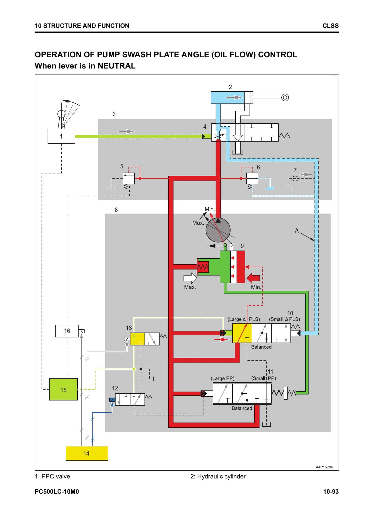
This is the largest technical section of the manual. It opens with the boot-up system, system operating lamp, and battery disconnect switch. The engine system chapter covers the engine control system, auto-deceleration system, engine automatic warm-up, overheat prevention, turbocharger protection, and automatic idle stop. Component parts of the engine system include the turbocharger, EGR valve, EGR cooler, and venturi system. The cooling system covers fan speed control and engine output control of the fan clutch. The hydraulic system chapter explains the closed-center load sensing system (CLSS), unload valve operation, pump swash plate angle control, pressure compensation control, and the engine and pump combined control system. The main pump, LS valve, PC valve, LS-EPC valve, and PC-EPC valve are each described in detail. The control valve chapter covers pressure compensation valves, LS bypass plugs, Hi-valves, boom and arm regeneration circuits, merge-divider valves, LS separation valves, self-pressure reducing valves, travel junction valves, travel PPC shuttle valves, boom and arm hydraulic drift prevention valves, suction safety valves, arm quick return valves, variable back pressure valves, main relief valves, and 2-stage suction safety valves. The work equipment system covers the one-touch power maximizing system, machine push-up system, PPC lock system, work equipment and travel automatic lock system, and oil flow adjuster system for attachments. The swing system describes the swing motor, swing machinery, and swing circle. The travel system covers the travel motor, final drive, travel PPC valve, and center swivel joint. The undercarriage and frame chapter covers specifications, work equipment structure and function, clearance adjustment shims, cab mount, and cab tipping stopper.
20 Standard Value Table
This chapter provides the standard value tables for the engine and machine. Engine values include engine speed at high idle and low idle, boost pressure, exhaust gas temperature, exhaust gas color, valve clearance, EGR valve values, compression pressure, blowby pressure, fuel pressure, fuel return rate, engine oil pressure, and cooling fan speed. Machine values include engine speed when oil pressure of two pumps are relieved, control valve spool stroke, travel of control lever, operating effort of control lever and pedal, work equipment and swing and travel oil pressure, PC valve outlet pressure, PC-EPC valve outlet pressure, LS differential pressure, LS valve outlet pressure, LS-EPC valve outlet pressure, solenoid valve outlet pressure, PPC valve outlet pressure, swing performance, traveling performance, hydraulic drift, work equipment speed, operation time lag, oil leakage, and pump performance. Machine posture and procedures for measuring performance are included.
30 Testing and Adjusting
The testing and adjusting chapter is one of the most practical sections. It covers the tools for testing and adjusting with part numbers and sketches. Engine and cooling system tests include engine speed, boost pressure, exhaust gas temperature, exhaust gas color, valve clearance, compression pressure, blowby pressure, engine oil pressure, EGR valve driving oil pressure, fuel pressure, fuel return rate and leakage, and cooling fan speed. Power train tests include swing circle bearing clearance. Undercarriage tests include track tension. Hydraulic system tests include releasing remaining pressure, testing and adjusting oil pressure in work equipment, swing, and travel circuits, testing control circuit oil pressure, testing and adjusting oil pressure in pump PC control circuit, testing and adjusting oil pressure in pump LS control circuit, testing outlet pressure of solenoid valve, testing PPC valve outlet pressure, adjusting work equipment and swing PPC valves, testing parts causing hydraulic drift, testing oil leakage, bleeding air from hydraulic circuit, and testing and charging accumulator nitrogen gas pressure for attachments. Cab tests include cab tipping stopper and mirror adjustment. Electrical system tests include machine monitor operation, KOMTRAX terminal startup, rearview camera angle adjustment, engine controller voltage circuit, battery disconnect switch, and diode testing. The Pm Clinic service chapter includes a check sheet for the PC500LC-10M0.
40 Troubleshooting
The troubleshooting chapter is extensive. It begins with related information including general troubleshooting points, sequence of events, checks before troubleshooting, and inspection procedures. The failure codes table covers all known failure codes with their action levels and history categories. Troubleshooting by failure code is provided for each code. The electrical system troubleshooting (E mode) covers engine starting issues, preheating system problems, machine monitor display issues, caution lamp issues, fuel gauge and temperature gauge problems, auto-deceleration issues, working mode selection issues, travel speed issues, one-touch power maximizing issues, horn and alarm issues, wiper and washer issues, and monitoring indicator issues. The hydraulic and mechanical systems troubleshooting (H mode) covers all work equipment, swing, and travel issues, engine speed drops, fine control problems, work equipment speed and power issues, hydraulic drift issues, travel issues, swing issues, fan speed issues, and unusual noise issues. The engine troubleshooting (S mode) covers engine starting, cranking, misfiring, startability, pick-up, stalling, rough running, lack of power, black exhaust, oil consumption, fuel consumption, coolant issues, oil pressure drops, fuel and water mixing into oil, overheating, unusual noise, vibration, and air bleeding from fuel circuit.
50 Disassembly and Assembly
This chapter provides the special tools list with part numbers and sketches, coating materials list, and detailed procedures for removal, installation, disassembly, and assembly. Engine and cooling system procedures cover the supply pump assembly, injector assembly, cylinder head assembly, EGR valve assembly, EGR cooler assembly, starting motor assembly, muffler, alternator belt, fan belt, radiator assembly, hydraulic oil cooler assembly, aftercooler assembly, fan clutch assembly, fan, engine and main pump assembly, engine front oil seal, engine rear oil seal, engine hood assembly, fuel tank assembly, air cleaner assembly, and air conditioner condenser assembly. Power train procedures cover the travel motor and final drive assembly, final drive disassembly and assembly, swing motor and swing machinery assembly, swing machinery disassembly and assembly, and swing circle assembly. Undercarriage procedures cover track assembly separation and connection, sprocket, idler and idler cushion assembly, idler disassembly and assembly, idler cushion disassembly and assembly, track roller assembly, carrier roller assembly, revolving frame assembly, and counterweight assembly. Hydraulic system procedures cover the center swivel joint assembly, hydraulic tank assembly, main pump assembly, control valve assembly, work equipment PPC valve assembly, and travel PPC valve assembly. Work equipment procedures cover the work equipment assembly and cylinder assembly. Cab procedures cover the operator’s cab assembly, cab glass, front window assembly, floor frame assembly, air conditioner unit assembly, operator’s seat, seat belt, and front wiper assembly. Electrical system procedures cover the engine controller assembly, pump controller assembly, machine monitor assembly, and KOMTRAX terminal assembly.
60 Maintenance Standard
The maintenance standard chapter provides the standard values for judging whether parts should be replaced or can be reused. It covers the engine mount, cooling system, swing circle, swing machinery, final drive, sprocket, sprocket tooth profile, track frame and idler cushion, idler, track roller, carrier roller, track shoe, triple shoe, main pump, swing motor, travel motor, control valve, work equipment and swing PPC valve, travel PPC valve, 1st-line attachment PPC valve, solenoid valve, attachment circuit selector valve, center swivel joint, work equipment linkage, boom cylinder, arm cylinder, and bucket cylinder.
80 Appendix (Air Conditioner)
The appendix covers the air conditioner system. It includes precautions for refrigerant, component specifications, configuration and function of the refrigeration cycle, component parts of the air conditioner system, air conditioner unit, air conditioner controller, compressor, condenser, receiver drier, and sensors. It also provides testing and troubleshooting procedures for the air conditioner including air leakage testing, self-diagnosis function, vent mode changeover testing, fresh/recirc air changeover testing, sunlight sensor testing, pressure switch testing, relay testing, and troubleshooting charts. Failure codes are listed with their meanings.
90 Circuit Diagrams
The circuit diagrams chapter includes the hydraulic circuit diagram with symbols, hydraulic circuit diagrams for specific operations including boom raised and upper structure swung left, and the complete hydraulic circuit diagram in two parts. The electrical circuit diagram includes symbols, the complete electrical circuit diagram in seven parts, and the connector and wiring harness chart in fifteen parts. This is essential for troubleshooting electrical and hydraulic problems.
Who This Manual Is For
This shop manual is written for professional technicians, mechanics, and service engineers who maintain and repair Komatsu PC500LC-10M0 hydraulic excavators. It is also valuable for owners and operators who want to understand the machine’s systems, perform their own maintenance, or diagnose problems before calling a dealer. The level of detail supports both routine service and major component overhaul.
Why This Manual Matters
The PC500LC-10M0 is a large hydraulic excavator with complex systems. The SAA6D125E-5 engine, the closed-center load sensing hydraulic system, the electronic control systems, and the undercarriage all require specific procedures and values. Using the wrong torque, clearance, or adjustment can lead to premature failure, poor performance, or safety issues. This manual gives the exact values, step-by-step procedures, and diagnostic flowcharts needed to do the job correctly.
The troubleshooting sections are particularly valuable. The E-mode, H-mode, and S-mode troubleshooting guides walk through symptoms systematically. Failure codes are listed with their action levels and histories so you can quickly identify what the machine is reporting. The hydraulic and electrical circuit diagrams help trace problems through the system.
IMAGES PREVIEW
Instant PDF Delivery
This Komatsu PC500LC-10M0 shop manual is delivered as a PDF download immediately after payment. There is no shipping, no waiting for a physical book, and no risk of a damaged or lost package. You can access the manual on any device that reads PDF files, including laptops, tablets, and smartphones. Print the pages you need for the workshop, or keep the entire manual on your device for quick reference. The PDF format makes it easy to search for specific terms, jump to sections, and carry the entire manual wherever you work.
Whether you are servicing a single machine or running a fleet of PC500LC-10M0 excavators, this manual provides the technical information you need to keep them running correctly. It covers everything from routine maintenance to complete teardown and rebuild, with the specifications and procedures that Komatsu technicians use.
Reviews
There are no reviews yet.