Trusted Business
Verified & Licensed
Virus Free Files
100% Safe Downloads
Secure Payment
SSL Protected
Instant Delivery
Available Immediately
Sale!


Komatsu PC600-7 Hydraulic Excavator Field Assembly Manual – PDF DOWNLOAD
Original price was: $74.95.$24.95Current price is: $24.95.
Komatsu PC600-7 Hydraulic Excavator Field Assembly Manual
MACHINE MODEL SERIAL NUMBER
PC600-7 20001 and up
PCSOOLC-7 20001 and up
Instant PDF Download
Available immediately
Save to Your Device
Download & keep forever
Antivirus Scanned
100% virus-free
Trusted Worldwide
175,000+ customers
Description
Komatsu PC600-7 Hydraulic Excavator Field Assembly Manual
FILE DETAILS:
Komatsu PC600-7 Hydraulic Excavator Field Assembly Manual
Language : English
Pages : 87
Downloadable : Yes
File Type : PDF
Size: 45.9 MB
Book Code: GEN00013-01
KOMATSU PC600-7 HYDRAULIC EXCAVATOR FIELD ASSEMBLY MANUAL – PDF DOWNLOAD:
DESCRIPTION:
Komatsu PC600-7 Hydraulic Excavator Field Assembly Manual
FOREWORD:
- With this machine, the work equipment is extremely heavy and the hydraulic pressure of the chassis is used to install it efficiently. For this reason. start the unglne and actuate the hydraulic cylinders. Before starting the engine and assembling the work equipment, It is necessary‘to carry out thorough inspection and maintenance. in addition. this work is frequently carried out with more than one worker in a dangerous place and posture.
- To ensure safety, carry out a safety meeting before starting and decide the operation leader and the person to give signals to the crane to ensure that all workers can carry out the operation in safety. Particularly in places where the workers speak different languages or have different customs. there are various causes of safety problems, so the local liaison officer and person in charge of the operation should consider fully the above palms and take action to ensure safety.
TABLE OF CONTENTS:
Komatsu PC600-7 Hydraulic Excavator Field Assembly Manual
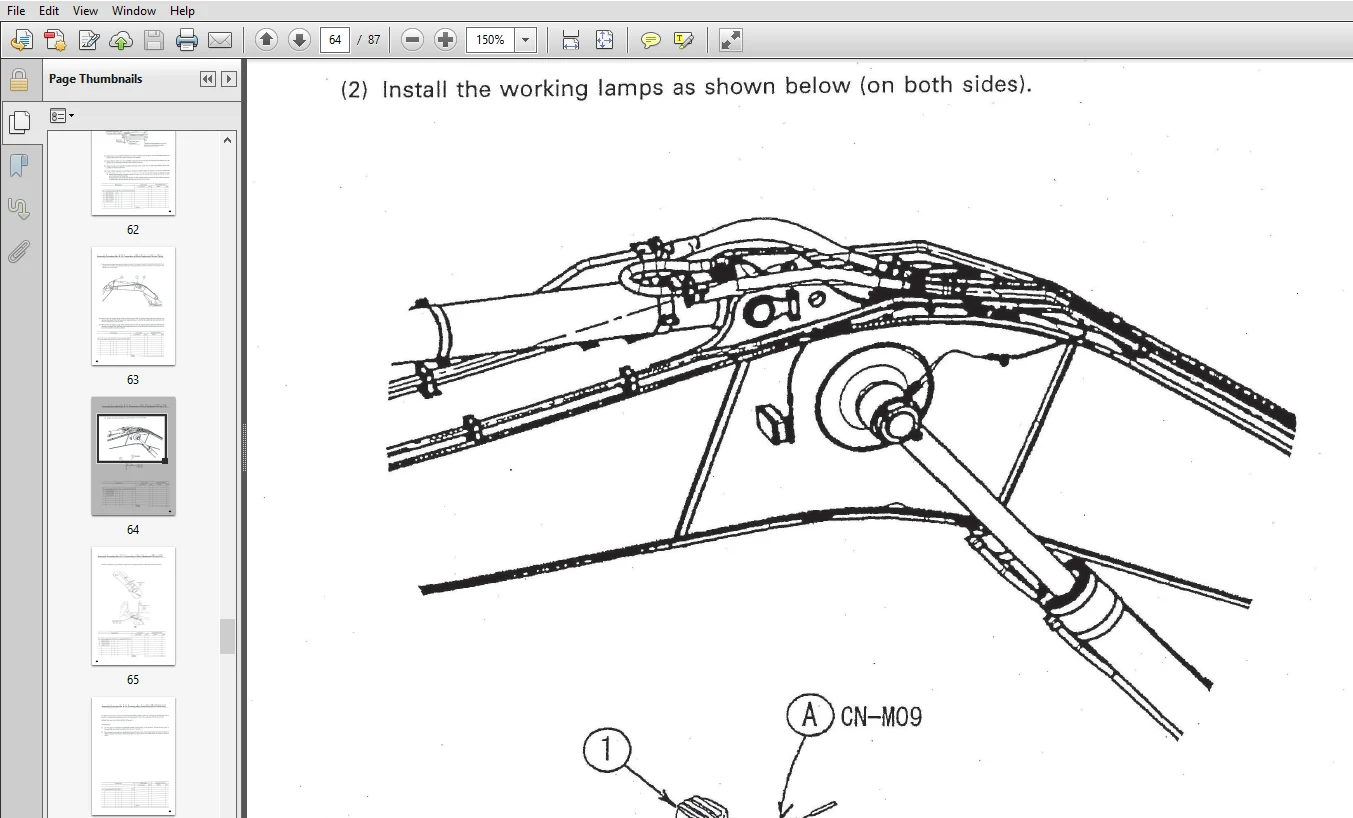
COVER............................................................................... 1
FOREWORD............................................................................ 2
CONTENTS............................................................................ 3
SPECIFICATIONS...................................................................... 4
FIELD ASSEMBLING.................................................................... 5
ASSEMBLING PROCEDURES, APPLICABLE EQUIPMENT AND SCHEDULE............................ 6
TRANSPORTATION...................................................................... 8
PACKING STYLE FOR TRANSPORTATION.................................................... 8
LIST OF TOOLS FOR FIELD ASSEMBLING..................................................12
STANDARD TIGHTENING TORQUE..........................................................13
A. ASSEMBLY OF BASE MACHINE.........................................................17
	A-1. INSTALLATION OF LEFT AND RIGHT TRACK FRAMES................................18
	A-2. INSTALLATION OF TRAVEL PIPE................................................21
	A-3. INSTALLATION OF TOP GUARD..................................................23
	A-4. INSTALLATION OF REARVIEW MIRROR............................................24
	A-5. INSTALLATION OF HANDRAIL...................................................27
	A-6. INSTALLATION OF STEP.......................................................30
	A-7. INSTALLATION OF LEFT SIDE STEP.............................................31
	A-8. STICKING SEAT TO COUNTERWEIGHT.............................................32
	A-9. REMOVAL OF MUFFLER TAIL PIPE...............................................33
	A-10. INSTALLATION OF COUNTERWEIGHT.............................................34
	A-11. INSTALLATION OF MUFFLER TAIL PIPE.........................................35
	A-12. INSTALLATION OF ORBCOMM ANTENNA (IF EQUIPPED).............................36
	A-13. INSTALLATION OF STEP LIGHT................................................37
	A-14. EXTENSION OF TRACK FRAME GAUGE............................................39
	A-15. INSTALLATION OF TRAVEL PIPING COVER.......................................43
	A-16. TESTING TRACK SHOE TENSION................................................44
	A-17. INSPECTION OF OIL AMOUNT AND WATER AMOUNT.................................47
	A-18. PARTS TO BE TOUCHED UP AFTER FIELD ASSEMBLY...............................49
B. ASSEMBLING OF WORK EQUIPMENT.....................................................50
	B-1. ASSEMBLY OF BOOM FOOT PIN, BOOM CYLINDER FOOT PIN..........................51
	B-2. ASSEMBLY OF BOOM ASSEMBLY..................................................52
	B-3. INSTALLATION OF BOOM CYLINDER FOOT.........................................53
	B-4. INSTALLATION OF BOOM CYLINDER HOSES........................................54
	B-5. INSTALLATION OF HOSES FROM CHASSIS ALONG TOP OF BOOM.......................55
	B-6. ASSEMBLY OF BOOM CYLINDER..................................................56
	B-7. ASSEMBLY OF ARM CYLINDER...................................................57
	B-8. INSTALLATION OF ARM CYLINDER HOSES.........................................58
	B-9. INSTALLATION OF ARM ASSEMBLY...............................................59
	B-10. INSTALLATION OF BUCKET CYLINDER HOSES BETWEEN BOOM AND BUCKET CYLINDER....61
	B-11. INSTALLATION OF BUCKET....................................................62
	B-12. CONNECTION OF WORK EQUIPMENT GREASE PIPING................................63
	B-13. CONNECTION OF WORK EQUIPMENT WIRING.......................................64
	B-14. GREASING AFTER ASSEMBLING WORK EQUIPMENT..................................66
M. PROCEDURE FOR INSPECTION AND MAINTENANCE AFTER COMPLETION OF ASSEMBLY............67
	M-1. INSPECTION OF OIL LEVEL IN HYDRAULIC TANK AND REFILL.......................68
	M-2. REPLACEMENT OF RETURN FILTER (STANDARD FILTER TO FLUSHING FILTER)..........70
	M-3. FLUSHING OF HYDRAULIC CIRCUIT..............................................73
FIELD ASSEMBLY INSPECTION REPORT (BACKHOE)..........................................75
IMAGES PREVIEW OF THE MANUAL:
PLEASE NOTE:
- This is the SAME manual used by the dealers to troubleshoot any faults in your vehicle. This can be yours in 2 minutes after the payment is made.
- Contact us at [email protected] should you have any queries before your purchase or that you need any other service / repair / parts operators manual.


Frankie Adler –