Komatsu PC750-6, PC750SE-6, PC750LC-6, PC800-6, PC800SE-6 Excavator Shop Manual SEBM008707 – PDF DOWNLOAD
Original price was: $61.95.$34.95Current price is: $34.95.
Komatsu PC750-6, PC750SE-6, PC750LC-6, PC800-6, PC800SE-6 Excavator Shop Manual
MACHINE MODEL SERIAL NUMBER
PC750-6 10001 and up
PC750SE-6 10001 and up
PC750LC-6 10001 and up
PC800-6 30001 and up
PC800SE-6 30001 and up
Description
Komatsu PC750-6, PC750SE-6, PC750LC-6, PC800-6, PC800SE-6 Excavator Shop Manual
FILE DETAILS:
Komatsu PC750-6, PC750SE-6, PC750LC-6, PC800-6, PC800SE-6 Excavator Shop Manual
Brands: Komatsu
Equipment Type: Hydraulic Excavator
Manuals Type: Shop Manual
Machine Model: PC750-6, PC750SE-6, PC750LC-6, PC800-6, PC800SE-6
Serial Number: 10001 and up, 30001 and up
Book Code: SEBM008707
Language: English
Pages: 981
File Format: Portable Document Format (PDF)
KOMATSU PC750-6, PC750SE-6, PC750LC-6, PC800-6, PC800SE-6 EXCAVATOR SHOP MANUAL SEBM008707 – PDF DOWNLOAD:
DESCRIPTION:
Komatsu PC750-6, PC750SE-6, PC750LC-6, PC800-6, PC800SE-6 Excavator Shop Manual
FOREWORD
GENERAL
- This shop manual has been prepared as an aid to improve the quality of repairs by giving the serviceman an accurate understanding of the product and by showing him the correct way to perform repairs and make judgements. Make sure you understand the contents of this manual and use it to full effect at every opportunity.
- This shop manual mainly contains the necessary technical information for operations performed in a service workshop. For ease of understanding, the manual is divided into the following chapters; these chapters are further divided into the each main group of components.
STRUCTURE AND FUNCTION
This section explains the structure and function of each component. It serves not only to give an understanding of the structure, but also serves as reference material for troubleshooting.
TESTING AND ADJUSTING
This section explains checks to be made before and after performing repairs, as well as adjustments to be made at completion of the checks and repairs. Troubleshooting charts correlating “Problems” to “Causes” are also included in this section.
DISASSEMBLY AND ASSEMBLY
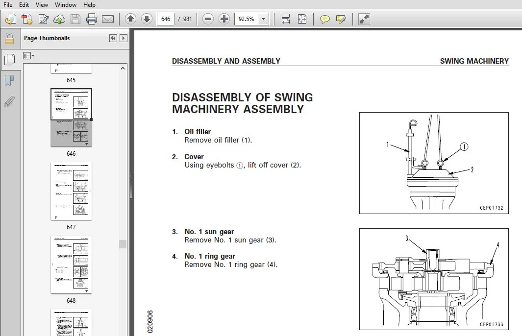
This section explains the order to be followed when removing, installing, disassembling or assembling each component, as well as precautions to be taken for these operations.
MAINTENANCE STANDARD
This section gives the judgement standards when inspecting disassembled parts.
TABLE OF CONTENTS:
Komatsu PC750-6, PC750SE-6, PC750LC-6, PC800-6, PC800SE-6 Excavator Shop Manual
MAIN MENU.................................................................................................................................................  0
COVER.....................................................................................................................................................  1
CONTENTS..................................................................................................................................................  2
01 GENERAL................................................................................................................................................ 28
	Specification drawings................................................................................................................................ 29
	Specifications........................................................................................................................................ 35
	Weight table.......................................................................................................................................... 51
	Fuel, coolant and lubricants.......................................................................................................................... 61
10 STRUCTURE AND FUNCTION................................................................................................................................. 64
	PTO................................................................................................................................................... 65
	PTO lubrication system................................................................................................................................ 66
	Radiator, oil cooler, aftercooler..................................................................................................................... 67
	Power train........................................................................................................................................... 69
	Swing machinery....................................................................................................................................... 71
	Swing circle.......................................................................................................................................... 72
	Final drive........................................................................................................................................... 73
	Track frame........................................................................................................................................... 74
	Track shoe............................................................................................................................................ 75
	Air piping diagram.................................................................................................................................... 76
	Air circuit diagram................................................................................................................................... 77
	Air governor.......................................................................................................................................... 78
	Air tank.............................................................................................................................................. 78
	Safety valve.......................................................................................................................................... 79
	Horn valve............................................................................................................................................ 79
	Grease pump........................................................................................................................................... 80
	Hydraulic piping drawing.............................................................................................................................. 81
	Hydraulic circuit drawing............................................................................................................................. 84
	Hydraulic tank........................................................................................................................................ 86
	Hydraulic pump........................................................................................................................................ 87
	Line oil filter.......................................................................................................................................129
	Pilot oil filter......................................................................................................................................129
	Return oil filter.....................................................................................................................................130
	Drain oil filter......................................................................................................................................130
	L.H. 5-spool control valve............................................................................................................................131
	R.H. 4-spool control valve............................................................................................................................133
	Swing motor...........................................................................................................................................139
	Center swivel joint...................................................................................................................................143
	Travel motor..........................................................................................................................................144
	PPC control relief valve..............................................................................................................................155
	Safety lock valve.....................................................................................................................................156
	Accumulator...........................................................................................................................................157
	Valve control.........................................................................................................................................158
	Work equipment, swing PPC valve.......................................................................................................................159
	Travel PPC valve......................................................................................................................................163
	Solenoid valve assembly...............................................................................................................................167
	Work equipment........................................................................................................................................168
	Air conditioner.......................................................................................................................................171
	Actual electric wiring diagram........................................................................................................................173
	Electric circuit diagram..............................................................................................................................177
	Engine control........................................................................................................................................181
	Electronic control system.............................................................................................................................189
	Machine monitor system................................................................................................................................212
20 TESTING AND ADJUSTING..................................................................................................................................222
	Standard value table for engine related parts.........................................................................................................223
	Standard value table for chassis related parts........................................................................................................224
	Standard value table for electrical parts.............................................................................................................243
	Tools for testing, adjusting, and troubleshooting.....................................................................................................253
	Measuring engine speed................................................................................................................................254
	Measuring air supply pressure (boost pressure)........................................................................................................255
	Measuring exhaust temperature.........................................................................................................................256
	Measuring exhaust color...............................................................................................................................257
	Adjusting valve clearance.............................................................................................................................258
	Measuring compression pressure........................................................................................................................259
	Measuring blow-by pressure............................................................................................................................260
	Testing and adjusting fuel injection timing...........................................................................................................261
	Measuring engine oil pressure.........................................................................................................................262
	Testing and adjusting alternator belt tension.........................................................................................................263
	Testing and adjusting fan belt tension................................................................................................................263
	Testing and adjusting belt tension for air conditioner compressor.....................................................................................264
	Testing and adjusting governor motor lever stroke.....................................................................................................265
	Adjusting engine speed sensor.........................................................................................................................266
	Testing and adjusting hydraulic pressure in work equipment, swing, travel circuit.....................................................................267
	Testing and adjusting control pump circuit oil pressure...............................................................................................270
	Testing and adjusting piston pump control pressure....................................................................................................273
	Measuring servo piston stroke ........................................................................................................................286
	Measuring PPC valve output pressure and testing PPC shuttle valve.....................................................................................287
	Testing solenoid valve output pressure................................................................................................................288
	Adjusting work equipment swing PPC valve..............................................................................................................289
	Testing travel deviation..............................................................................................................................290
	Testing locations causing hydraulic drift of work equipment...........................................................................................295
	Measuring oil leakage.................................................................................................................................296
	Testing clearance of swing circle bearing.............................................................................................................301
	Testing and adjusting track shoe tension..............................................................................................................303
	Bleeding air..........................................................................................................................................304
	TROUBLESHOOTING.......................................................................................................................................310
		Points to remember when troubleshooting...........................................................................................................311
		Sequence of events in troubleshooting.............................................................................................................312
		Points to remember when carrying out maintenance..................................................................................................313
		Checks before troubleshooting.....................................................................................................................321
		Connector types and mounting locations............................................................................................................323
		Connection table for connector pin numbers........................................................................................................327
		Explanation of control mechanism of electrical system.............................................................................................338
		Display method and special functions of monitor panel.............................................................................................340
		Method of using judgement table...................................................................................................................356
		Method of using troubleshooting charts............................................................................................................358
		Details of troubleshooting and troubleshooting procedure..........................................................................................360
		Service code table................................................................................................................................365
		Troubleshooting of communication abnormality system (N mode)......................................................................................366
			N-1	[E218] Communication abnormality..........................................................................................................367
		Troubleshooting of governor, pump controller [governor control system] (E mode)...................................................................370
			Points to remember when carrying out troubleshooting of governor, pump controller system......................................................371
			Action taken by controller and condition of machine when abnormality occurs...................................................................373
			Judgement table for governor, pump controller (governor control system) and engine related parts..............................................377
			Electrical circuit diagram of governor, pump controller (governor control system).............................................................379
			E- 1 Abnormality in governor, pump controller power source (controller LED is OFF)............................................................381
			E- 2 [E308] Abnormality in fuel control dial input value is displayed.........................................................................382
			E- 3 [E317] Abnormality (disconnection) in governor motor drive system is displayed...........................................................383
			E- 4 [E318] Abnormality (short circuit) in governor motor drive system is displayed...........................................................384
			E- 5 [E306] Abnormality in feedback potentiometer system is displayed.........................................................................385
			E- 6 [E315] Abnormality (short circuit) in battery relay output system is displayed...........................................................386
			E- 7 [E316] Abnormality (step-out) in motor is displayed......................................................................................387
			E- 8 Engine does not start....................................................................................................................389
			E- 9 Engine speed is irregular................................................................................................................391
				a) Idling speed is irregular..............................................................................................................391
				b) There is hunting.......................................................................................................................393
			E-10 Lack of output (engine high idling speed is too low).....................................................................................395
			E-11 Engine does not stop.....................................................................................................................397
			E-12 Defective operation of battery relay system (engine does not stop).......................................................................399
		Troubleshooting of engine (S mode)................................................................................................................402
			Method of using troubleshooting charts........................................................................................................403
			S- 1 Starting performance is poor (starting always takes time)................................................................................407
			S- 2 Engine does not start....................................................................................................................408
				1 Engine does not turn....................................................................................................................408
				2 Engine turns but exhaust gas does not comes out (fuel is not being injected)............................................................409
				3 Exhaust gas comes out but engine does not start (fuel is being injected)................................................................410
			S- 3 Engine does not pick up smoothly (follow-up is poor).....................................................................................411
			S- 4 Engine stops during operation............................................................................................................412
			S- 5 Engine does not rotate smoothly (hunting)................................................................................................413
			S- 6 Engine lacks output (no power)...........................................................................................................414
			S- 7 Exhaust gas is black (incomplete combustion).............................................................................................415
			S- 8 Oil consumption is excessive (or exhaust gas is blue)....................................................................................416
			S- 9 Oil becomes contaminated quickly.........................................................................................................417
			S-10 Fuel consumption is excessive............................................................................................................418
			S-11 Oil is in cooling water, or spurts back, or water level goes down........................................................................419
			S-12 Oil pressure caution lamp lights up (drop in oil pressure)...............................................................................420
			S-13 Oil level rises (water mixed with fuel)..................................................................................................421
			S-14 Water temperature becomes too high (overheating).........................................................................................422
			S-15 Abnormal noise is made...................................................................................................................423
			S-16 Vibration is excessive...................................................................................................................424
		Troubleshooting of governor, pump controller system [pump control system] (C mode)................................................................426
			Judgement table for governor, pump controller and hydraulic related parts.....................................................................427
			Points to remember when troubleshooting pump controller system................................................................................429
			Action taken by controller when abnormality occurs and problems on machine ...................................................................431
			Electrical circuit diagram for C mode.........................................................................................................437
			C- 1 Abnormality in controller power source system (controller LED is OFF)....................................................................439
			C- 2 [E232] Short circuit in front pump TVC solenoid system is displayed......................................................................440
			C- 3 [E233] Disconnection in front pump TVC solenoid system is displayed......................................................................442
			C- 4 [E203] Short circuit in rear pump TVC solenoid system is displayed.......................................................................444
			C- 5 [E213] Disconnection in swing holding brake solenoid system is displayed.................................................................446
			C- 6 [E201] Short circuit in CO cancel solenoid system is displayed...........................................................................448
			C- 7 [E211] Disconnection in CO cancel solenoid system is displayed...........................................................................449
			C- 8 [E202] Short circuit in straight travel solenoid system is displayed.....................................................................450
			C- 9 [E212] Disconnection in straight travel solenoid system is displayed.....................................................................451
			C-10 [E204] Short circuit in 2-stage relief solenoid system is displayed......................................................................452
			C-11 [E214] Disconnection in 2-stage relief solenoid system is displayed......................................................................453
			C-12 [E205] Short circuit in swing priority solenoid system is displayed......................................................................454
			C-13 [E215] Disconnection in swing priority solenoid system is displayed......................................................................455
			C-14 [E206] Short circuit in travel speed solenoid system is displayed........................................................................456
			C-15 [E216] Disconnection in travel speed solenoid system is displayed........................................................................457
			C-16 [E226] Abnormality in swing speed sensor power source system is displayed................................................................458
			C-17 [E207] Short circuit in swing overrun prevention solenoid system is displayed............................................................459
			C-18 [E208] Disconnection in swing overrun prevention solenoid system is displayed............................................................460
			C-19 [E217] Model selection input error is displayed..........................................................................................461
			C-20 [E227] Abnormality in engine speed sensor system is displayed............................................................................463
			C-21 Abnormality in machine push-up solenoid system (no service code displayed)...............................................................464
			C-22 Abnormality in shockless boom solenoid system (no service code displayed)................................................................467
		Troubleshooting of engine throttle, pump controller [input signal system] (F mode)................................................................470
			Electrical circuit diagram for F mode.........................................................................................................471
			F- 1 Bit pattern 20-(1) Swing oil pressure switch does not light up...........................................................................473
			F- 2 Bit pattern 20-(2) R.H. travel oil pressure switch does not light up.....................................................................474
			F- 3 Bit pattern 20-(3) Boom LOWER oil pressure switch does not light up......................................................................475
			F- 4 Bit pattern 20-(4) Boom RAISE oil pressure switch does not light up......................................................................476
			F- 5 Bit pattern 20-(5) Arm IN oil pressure switch does not light up..........................................................................477
			F- 6 Bit pattern 20-(6) Arm OUT oil pressure switch does not light up.........................................................................478
			F- 7 Bit pattern 21-(1) Bucket CURL oil pressure switch does not light up.....................................................................479
			F- 8 Bit pattern 21-(2) Bucket DUMP, service oil pressure switch does not light up............................................................480
			F- 9 Bit pattern 21-(5) L.H. travel oil pressure switch does not light up.....................................................................481
			F-10 Bit pattern 21-(3) Swing lock switch does not light up...................................................................................482
			F-11 Bit pattern 25-(4) Swing speed sensor does not light up..................................................................................483
		Troubleshooting of hydraulic, mechanical system (H mode)..........................................................................................484
			Table of failure modes and causes.............................................................................................................485
			Before carrying out troubleshooting of hydraulic system (H mode)..............................................................................487
			All work equipment, travel, swing.............................................................................................................491
			H-1 Speeds of all work equipment, swing, travel are slow or lack power........................................................................491
			H-2 There is excessive drop in engine speed, or engine stalls.................................................................................492
			H-3 No work equipment, travel, swing move.....................................................................................................494
			H-4 Abnormal noise generated (around pump)....................................................................................................495
			H-5 Auto-deceleration does not work...........................................................................................................495
			Work equipment................................................................................................................................496
			H-6 Work equipment speed is slow (boom, arm, bucket)..........................................................................................496
			H-7 Work equipment (boom, arm, bucket) does not move (but travel and swing are normal)........................................................497
			H-8 Excessive hydraulic drift.................................................................................................................497
			H-9 Excessive time lag........................................................................................................................498
			H-10 Excessive shock when boom is stopped.....................................................................................................498
			H-11 Defective actuation of machine push-up function..........................................................................................498
			H-12 In compound operations, work equipment is slow...........................................................................................499
			Travel system.................................................................................................................................500
			H-13 Travel deviation is excessive during compound operations.................................................................................500
			H-14 Machine deviates naturally to one side during travel operations..........................................................................502
			H-15 Deviation is excessive when srtarting....................................................................................................506
			H-16 Travel speed is slow.....................................................................................................................508
			H-17 Travel speed does not switch.............................................................................................................509
			H-18 Travel does not move (one side only).....................................................................................................509
			Swing system..................................................................................................................................510
			H-19 Does not swing...........................................................................................................................510
			H-20 Swing speed is slow or swing acceleration is poor........................................................................................511
			H-21 Swing speed is slow during compound operations...........................................................................................512
			H-22 Excessive overrun when stopping swing....................................................................................................512
			H-23 Excessive shock when stopping swing......................................................................................................513
			H-24 Excessive abnormal noise when stopping swing.............................................................................................513
			H-25 Excessive hydraulic drift of swing.......................................................................................................514
			H-26 Swing speed is faster than specified swing speed.........................................................................................515
		Troubleshooting of monitor panel system (M mode)..................................................................................................517
			Action taken by monitor panel when abnormality occurs and problems on machine.................................................................520
			Electrical circuit diagram for M mode system..................................................................................................522
			M-1 [E101] Abnormality in error data is displayed [E102] Error in clock data is displayed.....................................................524
			M-2 [E103] Short circuit in buzzer output or contact of 24V wiring harness with buzzer drive harness is displayed.............................525
			M-3 [E104] Air cleaner clogging detected is displayed.........................................................................................526
			M-4 [E106] Drop in engine oil pressure Hi detected is displayed...............................................................................526
			M-5 [E108] Engine water temperature 105℃ detected is displayed................................................................................527
			M-6 When starting switch is turned ON, none of lamps on monitor panel light up for 3 seconds..................................................528
			M-7 When starting switch is turned ON, monitor panel lamps all stay lighted up and do not go out..............................................530
			M-8 When starting switch is turned ON, items lighted up on monitor panel are  different from actual machine (model)...........................530
			M-9 When starting switch is turned ON (engine stopped), basic check items flash...............................................................531
			M-10 Preheating is not being used but preheating monitor lights up............................................................................534
			M-11 When starting switch is turned ON and engine is started, basic check items flash.........................................................535
			M-12 When starting switch is turned ON (engine stopped), caution items, emergency stop items flash............................................537
			M-13 When starting switch is turned ON and engine is started, caution items, emergency stop items flash.......................................539
			M-14 When starting switch is turned ON (engine stopped), buzzer does not sound for 1 second Caution item flashes but buzzer does not sound....543
			M-15 No abnormality is displayed on monitor but buzzer sounds.................................................................................543
			M-16 Night lighting on monitor panel does not light up (liquid crystal display is normal).....................................................544
			M-17 Coolant temperature gauge does not rise..................................................................................................545
			M-18 Coolant temperature gauge does not give any display......................................................................................545
			M-19 Fuel level gauge always displays FULL....................................................................................................546
			M-20 Fuel level gauge does not give any display...............................................................................................546
			M-21 Swing lock switch is turned ON (LOCK) but swing lock monitor does not light up...........................................................547
			M-22 Swing prolix switch is turned ON (prolix), but swing lock monitor does not flash.........................................................547
			M-23 Service meter does not advance while engine is running...................................................................................548
			M-24 When starting switch is at OFF and time switch is pressed, time and service meter are not displayed......................................548
			M-25 Defective fuel level sensor system.......................................................................................................549
			M-26 Defective coolant temperature sensor system..............................................................................................550
			M-27 Defective engine oil level sensor system.................................................................................................551
			M-28 Defective coolant level sensor system....................................................................................................552
			M-29 Defective hydraulic oil level sensor system..............................................................................................553
			M-30 Wiper does not work or switch is not being used but wiper is actuated....................................................................554
30 DISASSEMBLY AND ASSEMBLY...............................................................................................................................559
	METHOD OF USING MANUAL................................................................................................................................561
	PRECAUTIONS WHEN CARRYING OUT OPERATION...............................................................................................................564
	SPECIAL TOOL LIST ....................................................................................................................................566
	SKETCHES OF SPECIAL TOOLS ............................................................................................................................575
	STARTING MOTOR ASSEMBLY Removal, Installation.........................................................................................................579
	ALTERNATOR ASSEMBLY Removal, Installation.............................................................................................................580
	NOZZLE HOLDER ASSEMBLY Removal, Installation..........................................................................................................581
	ENGINE OIL COOLER ASSEMBLY Removal, Installation......................................................................................................583
	FUEL INJECTION PUMP ASSEMBLY Removal, Installation....................................................................................................584
	WATER PUMP ASSEMBLY Removal, Installation.............................................................................................................585
	TURBOCHARGER ASSEMBLY Removal, Installation...........................................................................................................586
	THERMOSTAT ASSEMBLY Removal, Installation.............................................................................................................587
	AIR COMPRESSOR ASSEMBLY Removal, Installation.........................................................................................................588
	ENGINE FRONT SEAL Removal, Installation...............................................................................................................589
	ENGINE REAR SEAL Removal, Installation................................................................................................................590
	GOVERNOR MOTOR ASSEMBLY Removal, Installation.........................................................................................................595
	CYLINDER HEAD ASSEMBLY Removal, Installation..........................................................................................................596
	AFTERCOOLER CORE Removal, Installation................................................................................................................603
	FAN GUARD, RADIATOR, HYDRAULIC COOLER ASSEMBLY Removal, Installation..................................................................................604
	HYDRAULIC COOLER, AFTERCOOLER ASSEMBLY Removal, Installation..........................................................................................607
	ENGINE, PTO, HYDRAULIC PUMP ASSEMBLY Removal, Installation ...........................................................................................609
	PTO ASSEMBLY Removal, Installation....................................................................................................................617
	PTO ASSEMBLY Disassembly, Assembly....................................................................................................................621
	FINAL DRIVE ASSEMBLY Removal, Installation............................................................................................................629
	FINAL DRIVE ASSEMBLY Disassembly, Assembly............................................................................................................630
	REVOLVING FRAME ASSEMBLY Removal, Installation........................................................................................................643
	SWING MACHINERY ASSEMBLY Removal, Installation........................................................................................................645
	SWING MACHINERY ASSEMBLY Disassembly, Assembly........................................................................................................646
	SWING CIRCLE ASSEMBLY Removal, Installation...........................................................................................................656
	TRACK SHOE ASSEMBLY Removal, Installation.............................................................................................................657
	ONE LINK IN FIELD Disassembly, Assembly...............................................................................................................659
	SPROCKET Removal, Installation........................................................................................................................663
	IDLER ASSEMBLY Removal, Installation..................................................................................................................664
	IDLER ASSEMBLY Disassembly, Assembly..................................................................................................................665
	IDLER ADJUSTMENT CYLINDER ASSEMBLY Disassembly, Assembly..............................................................................................669
	RECOIL SPRING ASSEMBLY Removal, Installation..........................................................................................................670
	RECOIL SPRING ASSEMBLY Disassembly, Assembly..........................................................................................................671
	CARRIER ROLLER ASSEMBLY Removal, Installation.........................................................................................................674
	CARRIER ROLLER ASSEMBLY Disassembly, Assembly.........................................................................................................675
	TRACK ROLLER ASSEMBLY Removal, Installation...........................................................................................................678
	TRACK ROLLER ASSEMBLY Disassembly, Assembly...........................................................................................................679
	TVC VALVE ASSEMBLY Removal, Installation..............................................................................................................682
	CO, NC VALVE ASSEMBLY Removal, Installation...........................................................................................................683
	SERVO VALVE ASSEMBLY Removal, Installation............................................................................................................685
	NO. 1 PUMP ASSEMBLY Removal, Installation.............................................................................................................686
		DISASSEMBLY AND ASSEMBLY..........................................................................................................................690
	NO. 2 PUMP ASSEMBLY Removal, Installation.............................................................................................................718
		DISASSEMBLY AND ASSEMBLY..........................................................................................................................722
	MAIN PUMP INPUT SHAFT OIL SEAL Removal, Installation..................................................................................................748
	CONTROL, PTO LUBRICATION PUMP ASSEMBLY Removal, Installation..........................................................................................749
	MAIN RELIEF VALVE ASSEMBLY Removal, Installation......................................................................................................751
	MAIN RELIEF VALVE ASSEMBLY Disassembly, Assembly......................................................................................................752
	CONTROL PUMP RELIEF VALVE ASSEMBLY Removal, Installation..............................................................................................753
	LEFT 5-SPOOL CONTROL VALVE ASSEMBLY Removal, Installation.............................................................................................754
	RIGHT 4-SPOOL CONTROL VALVE ASSEMBLY Removal, Installation............................................................................................755
	CONTROL VALVE ASSEMBLY Disassembly, Assembly..........................................................................................................759
	SWING MOTOR ASSEMBLY Removal, Installation............................................................................................................763
		DISASSEMBLY AND ASSEMBLY..........................................................................................................................764
	CENTER SWIVEL JOINT ASSEMBLY Removal, Installation....................................................................................................774
	CENTER SWIVEL JOINT ASSEMBLY Disassembly, Assembly....................................................................................................775
	TRAVEL MOTOR ASSEMBLY Removal, Installation...........................................................................................................776
		DISASSEMBLY AND ASSEMBLY..........................................................................................................................777
	WORK EQUIPMENT PPC VALVE ASSEMBLY Removal, Installation...............................................................................................808
	WORK EQUIPMENT PPC VALVE ASSEMBLY Disassembly, Assembly...............................................................................................809
	TRAVEL PPC VALVE ASSEMBLY Removal, Installation.......................................................................................................811
	TRAVEL PPC VALVE ASSEMBLY Disassembly, Assembly.......................................................................................................812
	BUCKET CYLINDER ASSEMBLY Removal, Installation........................................................................................................815
	ARM CYLINDER ASSEMBLY Removal, Installation...........................................................................................................819
	BOOM CYLINDER ASSEMBLY Removal, Installation..........................................................................................................823
	BOTTOM DUMP CYLINDER ASSEMBLY Removal, Installation...................................................................................................827
	HYDRAULIC CYLINDER ASSEMBLY Disassembly, Assembly.....................................................................................................830
	BUCKET ASSEMBLY Removal, Installation.................................................................................................................835
	ARM ASSEMBLY Removal, Installation....................................................................................................................839
	BOOM ASSEMBLY Removal, Installation...................................................................................................................843
	BUCKET, ARM ASSEMBLY Removal, Installation............................................................................................................847
	WORK EQUIPMENT ASSEMBLY Removal, Installation.........................................................................................................849
	OPERATOR'S CAB ASSEMBLY Removal, Installation.........................................................................................................853
	COUNTERWEIGHT ASSEMBLY Removal, Installation..........................................................................................................855
	AIR CONDITIONER COMPRESSOR ASSEMBLY Removal, Installation.............................................................................................856
	AIR CONDITIONER UNIT ASSEMBLY Removal, Installation...................................................................................................857
	GOVERNOR, PUMP CONTROLLER ASSEMBLY Removal, Installation..............................................................................................859
	MONITOR PANEL ASSEMBLY Removal, Installation..........................................................................................................860
	CONTROL STAND CASE Removal, Installation..............................................................................................................861
40 MAINTENANCE STANDARD...................................................................................................................................864
	Engine mount .........................................................................................................................................866
	PTO ..................................................................................................................................................867
	Swing circle..........................................................................................................................................869
	Swing machinery ......................................................................................................................................870
	Final drive  .........................................................................................................................................872
	Track frame  .........................................................................................................................................875
	Idler ................................................................................................................................................876
	Carrier roller .......................................................................................................................................878
	Track roller .........................................................................................................................................879
	Track shoe............................................................................................................................................880
	Hydraulic pump .......................................................................................................................................885
	Charging and PTO lubrication pump ....................................................................................................................887
	L.H. 5-spool control valve ...........................................................................................................................890
	R.H. 4-spool control valve ...........................................................................................................................892
	Swing motor...........................................................................................................................................895
	Travel motor..........................................................................................................................................896
	Center swivel joint...................................................................................................................................898
	PPC control relief valve..............................................................................................................................899
	PPC valve ............................................................................................................................................900
	Hydraulic cylinder ...................................................................................................................................902
	Work equipment .......................................................................................................................................908
	Dimensions of work equipment .........................................................................................................................914
90 OTHERS.................................................................................................................................................919
	Hydraulic piping drawing (Back hoe)...................................................................................................................920
		 PC750,PC750SE,PC750LC-6 SERIAL NO.: 10001-10238  -  PC800,PC800SE-6 SERIAL NO.: 30001-30174......................................................920
	Hydraulic piping drawing (Back hoe)...................................................................................................................922
		 PC750,PC750SE,PC750LC-6 SERIAL NO.: 10239 AND UP  -  PC800,PC800SE-6 SERIAL NO.: 30175 AND UP....................................................922
	Hydraulic piping drawing (Loading shovel).............................................................................................................923
	Hydraulic circuit drawing (Back hoe)..................................................................................................................924
		 PC750,PC750SE,PC750LC-6 SERIAL NO.: 10001-10238  -  PC800,PC800SE-6 SERIAL NO.: 30001-30174......................................................924
	Hydraulic circuit drawing (Loading shovel)............................................................................................................925
		 PC750-6  -   SERIAL NO.: 10001-10238.............................................................................................................925
	Hydraulic piping drawing (Back hoe)...................................................................................................................926
		 PC750,PC750SE,PC750LC-6  SERIAL NO.: 10239 AND UP  -  PC800,PC800SE-6 SERIAL NO.: 30175 AND UP...................................................926
	Hydraulic circuit drawing (Loading shovel)............................................................................................................931
		 PC750-6  -   SERIAL NO.: 10239 AND UP............................................................................................................931
	Actual electric wiring diagram (1/2) (Back hoe).......................................................................................................936
	Actual electric wiring diagram (2/2) (Back hoe).......................................................................................................937
	Actual electric wiring diagram (1/2) (Loading shovel).................................................................................................938
	Actual electric wiring diagram (2/2) (Loading shovel).................................................................................................939
	Electric circuit diagram (1/3) (Back hoe).............................................................................................................940
		 PC750,PC750SE,PC750LC-6 SERIAL NO.: 10001-10238  -  PC800,PC800SE-6 SERIAL NO.: 30001-30174......................................................940
	Electric circuit diagram (2/3) (Back hoe).............................................................................................................942
		 PC750,PC750SE,PC750LC-6 SERIAL NO.: 10001-10238  -  PC800,PC800SE-6 SERIAL NO.: 30001-30174......................................................942
	Electric circuit diagram (3/3) (Back hoe).............................................................................................................944
		 PC750,PC750SE,PC750LC-6 SERIAL NO.: 10001-10238  -  PC800,PC800SE-6 SERIAL NO.: 30001-30174......................................................944
	Electric circuit diagram (1/3) (Loading shovel) ......................................................................................................946
		 PC750-6  -   SERIAL NO.: 10238 AND UP............................................................................................................946
	Electric circuit diagram (2/3) (Loading shovel).......................................................................................................947
		 PC750-6  -   SERIAL NO.: 10238 AND UP............................................................................................................947
	Electric circuit diagram (3/3) (Loading shovel).......................................................................................................948
		 PC750-6  -   SERIAL NO.: 10238 AND UP............................................................................................................948
	Electric circuit diagram (1/3) (Back hoe).............................................................................................................949
		 PC750,PC750SE,PC750LC-6 SERIAL NO.: 10239 AND UP -  PC800,PC800SE-6 SERIAL NO.: 30175 AND UP.....................................................949
	Electric circuit diagram (2/3) (Back hoe).............................................................................................................954
		 PC750,PC750SE,PC750LC-6 SERIAL NO.: 10239 AND UP -  PC800,PC800SE-6 SERIAL NO.: 30175 AND UP.....................................................954
	Electric circuit diagram (3/3) (Back hoe).............................................................................................................959
		 PC750,PC750SE,PC750LC-6 SERIAL NO.: 10239 AND UP -  PC800,PC800SE-6 SERIAL NO.: 30175 AND UP.....................................................959
	Electric circuit diagram (1/3) (Loading shovel).......................................................................................................964
		 PC750-6  -   SERIAL NO.: 10239 AND UP............................................................................................................964
	Electric circuit diagram (2/3) (Loading shovel).......................................................................................................969
		 PC750-6  -   SERIAL NO.: 10239 AND UP............................................................................................................969
	Electric circuit diagram (3/3) (Loading shovel).......................................................................................................974
		 PC750-6  -   SERIAL NO.: 10239 AND UP............................................................................................................974
	Machine control system diagram .......................................................................................................................979
	Connector arrangement diagram (1/2)...................................................................................................................980
	Connector arrangement diagram (2/2)...................................................................................................................981
IMAGES PREVIEW OF THE MANUAL:
PLEASE NOTE:
- This is the SAME exact manual used by your dealers to fix your vehicle.
- The same can be yours in the next 2-3 mins as you will be directed to the download page immediately after paying for the manual.
- Any queries / doubts regarding your purchase, please feel free to contact [email protected]


Oscar Chance –
Aryan Khalil –