
Komatsu PC8000-6 Diesel Hydraulic Mining Shovel Service Manual – Serial 12046 and Up
Original price was: $44.95.$26.95Current price is: $26.95.
Complete Komatsu PC8000-6 Diesel service manual covering safety, engine drive, hydraulic pumps, ECS, lubrication, swing, travel, and all major systems. Serial number 12046 and up. Instant PDF download.
Description
Komatsu PC8000-6 Diesel Service Manual – Your Complete Workshop Reference
This Komatsu PC8000-6 Diesel service manual is the comprehensive workshop reference for one of the largest hydraulic mining shovels in operation. Covering machine serial number 12046 and up, this manual gives technicians and maintenance teams the complete technical documentation needed to understand, service, diagnose, and repair the PC8000-6 Diesel across every major system. From the safety foreword through to the lubrication systems, every section is structured to put the right procedure, adjustment, or specification at your fingertips.
File Details
- Manual Type: Service Manual
- Brand: Komatsu
- Manufacturer: Komatsu Mining Germany GmbH
- Model: PC8000-6 Diesel
- Serial Number: 12046 and up
- Language: English
- File Format: PDF
- Page Count: Approximately 610 pages
- Document Date: 14.10.05
Chapters Covered
The manual is organised into clearly defined sections, each dealing with a specific area of the machine:
- Safety – Foreword: Important safety notices, general precautions, preparation for work, precautions during work, environmentally friendly operation and maintenance, standard tightening torques, conversion tables, and wire rope safety data.
- Technical Data (Leaflet): Machine specifications and reference data.
- Assembly Procedure (Brochure): Procedure for assembling the machine.
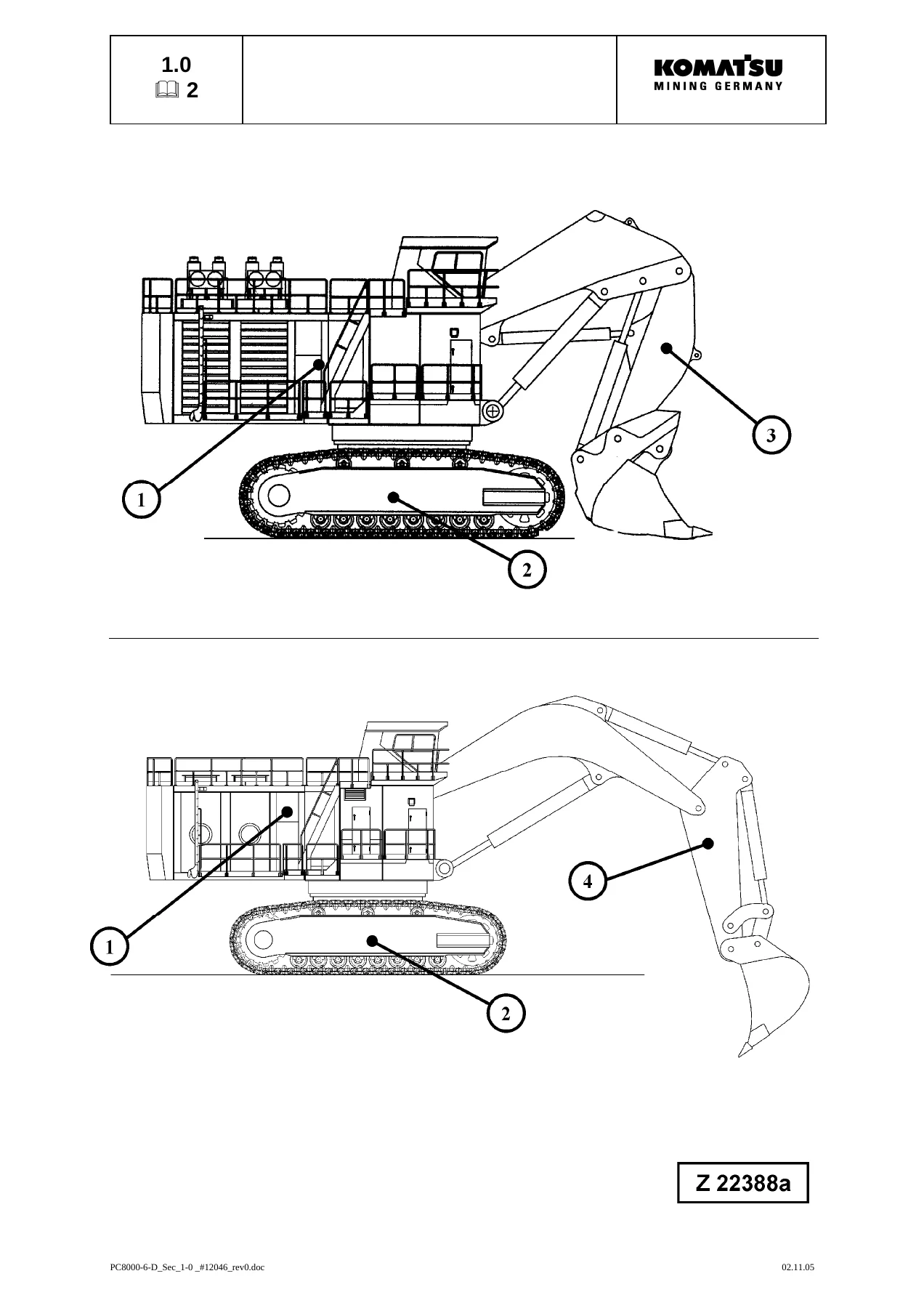
- 1. Main Assembly Groups: Superstructure (machinery house, hydraulic oil reservoir, hydraulic oil cooler, fuel tank, counterweight, cab support, operator’s cab, main pumps and control blocks, swing gears), undercarriage, and attachment (Backhoe Attachment BHA and Front Shovel Attachment FSA).
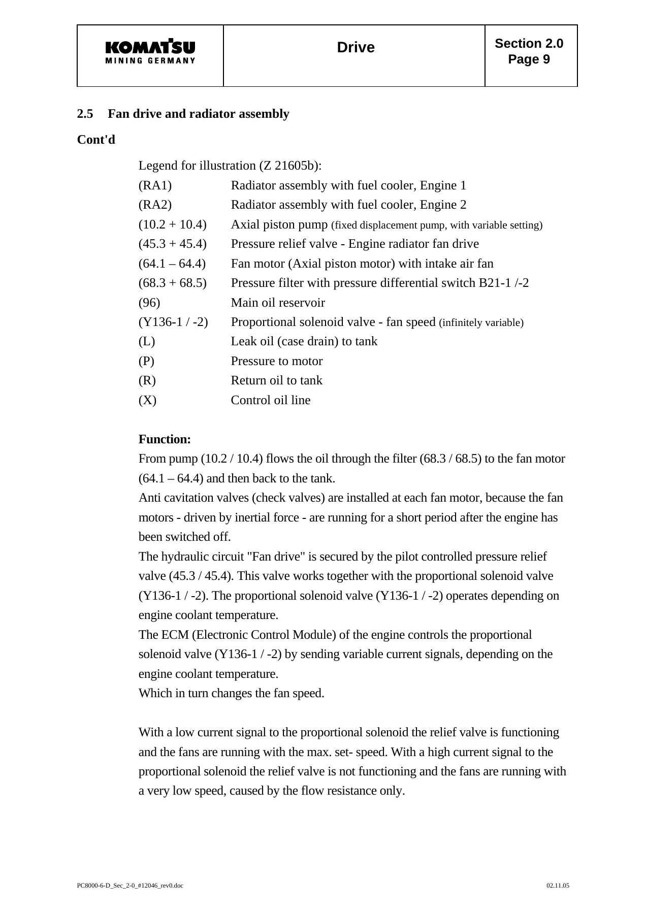
- 2. Drive: Prime drive assembly, engine and PTO mounts, drive shaft, flexible coupling, air filter, fan drive and radiator assembly, radiator fan drive speed adjustment, pump distributor gearbox (PTO), pump-spline lubrication, PTO lubrication and cooling, hydraulic pump location, drive speeds, and flow rates.
- 3. Hydraulic Oil Tank: Main oil tank, suction oil tank with strainers, return oil collector tube with strainer, back pressure valve, transfer pump, return and leak oil filter, and breather filter.
- 4. Hydraulic Oil Cooling: Hydraulic oil cooling circuit function, standard and additional cooling circuits, back pressure valve adjustment, fan drive of standard cooler, two-stage cooler fan RPM control, pressure relief valves and solenoid valves, fixed displacement pump with variable setting, fan drive speed adjustment, fan speed control function check, switch points, and fan drive of additional cooler.
- 5. Controlling: Control and filter panel component locations, pilot pressure supply and adjustments, remote control valve arrangement, function principle of the electro-hydraulic proportional control, potentiometer control (lever/joystick and pedal), proportional amplifier modules (Type A and Type B), ramp time module, and amplifier module adjustments.
- 6. Components: Main control blocks and high pressure filter, distributor manifold restrictor blocks, anti-cavitation valve blocks, remote control valves, directional solenoid valves, proportional solenoid valves, high pressure filter, control blocks and valves, travel brake valve, pressure reducing valve, pressure increasing valve, and hydraulic cylinder.
- 7. Main Hydraulic Pumps and Pump Regulation: Pump location and drive speeds, pump bearing flushing and lubrication, operating principles, checks and adjustments, electronic pump regulation system (Microcontroller MC7 with fault code diagnostics, checks and adjustments using three methods), hydraulic constant regulation system, determination of peak point, and engine speed sensor adjustment.
- 8. Operating Hydraulic: General layout and function.
- 8.1 Hydraulic for the Attachment Cylinders (FSA): Electric/hydraulic flowcharts for boom raising, boom lowering, stick extending, stick retracting, bucket filling, bucket emptying, clam opening, and clam closing. Checks and adjustments of main relief valves (MRV), service line relief valves (SRV) for boom, stick, bucket, and clam cylinders. Checks and adjustments for lowering speed.
- 8.2 Hydraulic for the Swing Circuit: Swing circuit description, swing motor, swing gearbox, swing parking brake, swing brake valve, electric/hydraulic flowcharts for swing left and swing right, checks and adjustments, function check for hydraulic swing brake, and function check for swing parking brake.
- 8.3 Hydraulic for the Travel Circuit: Travel circuit description, travel motor, rotary distributor, travel gearbox, travel parking brake, travel brake valve, electric/hydraulic flowcharts for travel forward and travel backward, checks and adjustments, and function check for travel parking brake.
- 9. Hydraulic Track Tensioning System: General, functional description, pressure increasing valve, tensioning cylinder, adjustments and checks, and functional test.
- 10. Hydraulic Operated Access Ladder: General, function, adjustments, and checks.
- 11. Central Refilling System: Hydraulic operated refilling arm – general and function.
- 12. Hints for Reading the Hydraulic Circuit Diagram: General, symbols (lines and unions, components and valves, sensors, valves and valve components, pumps, motors, cylinders, assemblies and main components).
- 13. Hints for Reading the Electric Circuit Diagram: Designation of electrical devices, symbols, general information, and reading a circuit diagram.
- 14. Electronic Control System – ECS: General design, inputs and outputs, PLC DIGSY plus, definitions and abbreviations, maintenance and installation procedures, status LED meanings, short circuit marker, diagnostics for temperature module, front connector arrangement, power supply, function explanations with electrical diagram, pressure measuring, temperature measuring, PT100 temperature-resistance chart, and hints for reading functional flow charts.
- 15. Lubrication Systems: General function, oscillation cylinder and control block, adjustments, one-line system, electrical function, capacitive analog sensor for lubricant level monitoring, end-line pressure switch adjustments, injectors, pinion type (dummy wheel) system, hydraulically driven lube pump, in-line filter, vent valve, and troubleshooting.
This PC8000-6 Diesel service manual is far more than a parts list. It is a complete technical training and repair resource that explains how each system works, how components interact, and exactly how to carry out inspections, adjustments, and repairs. The inclusion of electric/hydraulic flowcharts for every major attachment, swing, and travel function makes it possible to trace faults systematically through both the electrical control and hydraulic power circuits. The Electronic Control System section, with its PLC diagnostics, LED status tables, and analogue sensor measuring procedures, is essential for anyone maintaining the advanced control architecture of this machine. The lubrication system section covers both the central lubrication and slew ring gear systems in detail, including injector operation and end-of-line switch adjustment.
What This Manual Enables You to Do
With this Komatsu PC8000-6 Diesel service manual on hand, you can confidently tackle the full range of maintenance and repair tasks that keep this mining shovel productive. The manual supports:
- Understanding the complete hydraulic system, from pump regulation through control blocks to individual cylinder and motor functions
- Diagnosing electrical and hydraulic faults using the flowcharts and circuit diagram hints
- Adjusting main relief valves, service line relief valves, and pressure increasing valves to factory specifications
- Checking and setting pilot pressure, back pressure, and pump regulation pressures
- Servicing the swing and travel circuits, including brake function checks
- Maintaining the hydraulic track tensioning system and access ladder hydraulics
- Programming and troubleshooting the Electronic Control System (ECS) with PLC diagnostics
- Servicing the lubrication systems, including injector adjustment and end-of-line switch setting
- Carrying out engine mount checks, drive shaft and coupling inspections, and PTO gearbox maintenance
- Reading and interpreting both hydraulic and electric circuit diagrams
Correct procedures and accurate specifications are critical on a machine of this size and complexity. An incorrectly adjusted relief valve can cause overheating, reduced performance, or catastrophic component failure. A misdiagnosed electrical fault can lead to unnecessary downtime and expensive part replacement. This manual removes the guesswork by providing the manufacturer’s own procedures, adjustment values, and diagnostic logic. Whether you are a seasoned field service technician, a workshop supervisor, or a maintenance planner, this document gives you the information you need to work efficiently and safely.
IMAGES PREVIEW
Instant PDF Delivery
This Komatsu PC8000-6 Diesel service manual is delivered as an instant PDF download. There is no shipping, no waiting for a physical book, and no restrictions on how many times you access it. The PDF can be viewed on any device – laptop, desktop, tablet, or smartphone – and specific pages can be printed for use in the workshop or field. Keep it on your service truck’s laptop, share it with your maintenance team, or print the sections you need for a specific job. With approximately 610 pages of detailed technical content, this manual is a complete reference library for the PC8000-6 Diesel in one convenient file.


Reviews
There are no reviews yet.