Komatsu PC80MR-3 Hydraulic Excavator Shop Manual SN F00003 and up – PDF DOWNLOAD
Original price was: $56.95.$28.95Current price is: $28.95.
Komatsu PC80MR-3 Hydraulic Excavator Shop Manual
SERIAL NUMBER : PC80MR-3 F00003 and up
Book Code: WEBM008601
Description
Komatsu PC80MR-3 Hydraulic Excavator Shop Manual
FILE DETAILS:
Komatsu PC80MR-3 Hydraulic Excavator Shop Manual
Brands: Komatsu
Equipment Type: Hydraulic Excavator
Manuals Type: Shop Manual
Machine Model: PC80MR-3
Serial Number: F00003 and up
Book Code: WEBM008601
Language: English
Pages: 302
File Format: Portable Document Format (PDF)
KOMATSU PC80MR-3 HYDRAULIC EXCAVATOR SHOP MANUAL SN F00003 AND UP – PDF DOWNLOAD:
IMAGES PREVIEW OF THE MANUAL:
DESCRIPTION:
Komatsu PC80MR-3 Hydraulic Excavator Shop Manual
FOREWORD:
- This shop manual has been prepared as an aid to improve the quality of repairs by giving the operator an accurate understanding of the product and by showing him the correct way to perform repairs and make judgements. Make sure you understand the contents of this manual and use it to full effect at every opportunity.
- This shop manual mainly contains the necessary technical information for operations performed in a service workshop. The manual is divided into chapters on each main group of components; these chapters are further divided into the following sections.
STRUCTURE AND FUNCTION:
This section explains the structure and function of each component. It serves not only to give an understanding of the structure, but also serves as reference material for troubleshooting.
TESTING AND ADJUSTMENTS:
This sections explains checks to be made before and after performing repairs, as well as adjustments to be made at completion of the checks and repairs. Troubleshooting charts correlating «Problems» to «Causes» are also included in this section.
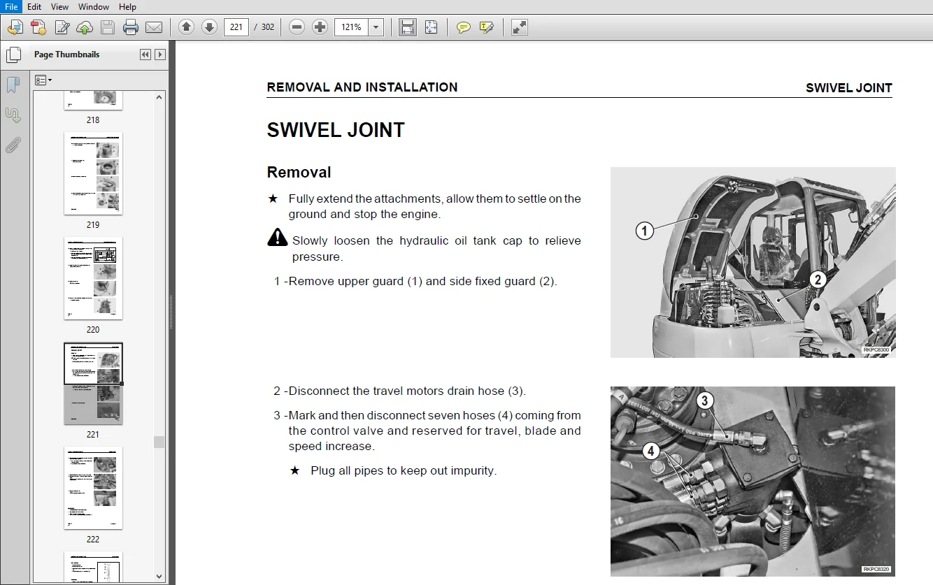
REMOVAL AND INSTALLATION:
This section explains the order to be followed when removing, installing, disassembling or assembling each component, as well as precautions to be taken for these operations.
TABLE OF CONTENTS:
Komatsu PC80MR-3 Hydraulic Excavator Shop Manual
CONTENTS.............................................................................  3
REVISED PAGES........................................................................  5
k SAFETY.............................................................................  7
FOREWORD.............................................................................  9
HOW TO READ THE SHOP MANUAL.......................................................... 10
HOISTING INSTRUCTIONS................................................................ 11
STANDARD TIGHTENING TORQUE........................................................... 12
COATING MATERIALS.................................................................... 14
ELECTRIC............................................................................. 15
WEIGHT TABLE......................................................................... 16
TABLE OF OIL AND COOLANT QUANTITIES.................................................. 17
CONVERSION TABLE..................................................................... 19
10 STRUCTURE AND FUNCTION............................................................ 27
	POWER TRAIN...................................................................... 28
	SWING CIRCLE..................................................................... 29
	SWING MACHINERY.................................................................. 31
	TRACK FRAME AND IDLER CUSHION.................................................... 34
	IDLER............................................................................ 36
	TRACK ROLLER..................................................................... 37
	CARRIER ROLLER................................................................... 38
	SPROCKET......................................................................... 39
	TRACK SHOE....................................................................... 40
	SHOES............................................................................ 43
	RUBBER SHOE...................................................................... 44
	SWIVEL JOINT..................................................................... 45
	TRAVEL MOTOR..................................................................... 46
	WORK EQUIPMENT CYLINDER.......................................................... 48
	SOLENOID VALVE GROUP............................................................. 52
	CONTROL VALVE.................................................................... 54
	CLSS............................................................................. 65
	SWING MOTOR...................................................................... 84
	ATTACHMENT....................................................................... 93
	TRAVEL PPC VALVE................................................................. 98
	BLADE, BOOM SWING, 2-PIECE BOOM PPC VALVES.......................................102
	EQUIPMENT........................................................................106
20 TESTING AND ADJUSTMENTS...........................................................109
	NORMAL OR STANDARD TECHNICAL DATA................................................111
		FOR THE ENGINE...............................................................111
		FOR MACHINE..................................................................112
	PUMP FEATURES....................................................................119
	CHECK POSITIONS..................................................................120
	SPECIAL TOOLS....................................................................125
	MEASURING THE ENGINE SPEED.......................................................127
		1. Measuring engine speed....................................................127
		2. Measuring engine speed to check compression pressure......................128
	CHECKING THE EXHAUST SMOKE COLOUR................................................129
		1. Checking with tool G1.....................................................129
		2. Checking with tool G2.....................................................129
	REMOVAL OF VALVES COVER..........................................................131
	ADJUSTING VALVE CLEARANCE........................................................133
	MEASURING COMPRESSION PRESSURE...................................................136
	TESTING AND ADJUSTING FUEL INJECTION TIMING......................................138
		Test.........................................................................138
		Adjustment procedure.........................................................140
	CHECKING ENGINE OIL PRESSURE.....................................................142
	CHECKING AND REGULATING PRESSURE IN THE HYDRAULIC CIRCUITS.......................143
	CHECKING AND CALIBRATING PRESSURE IN THE SECONDARY VALVES........................145
		1. Preparing the machine.....................................................145
		2. Checking revolving frame rotational pressure..............................145
		3. Adjusting general valve for revolving frame rotation and blade circuit....146
		4. Checking boom, arm, bucket, boom swing and travel pressure................146
		5. Adjusting secondary valve for boom, arm, bucket, boom swing and travel....147
		6. Checking Unloading pressure...............................................147
	CHECKING AND ADJUSTING THE LS (Load Sensing) VALVE...............................148
		1. Measuring DPLS differential pressure......................................148
		2. With analog pressure gauge................................................149
		3. Adjusting the valve.......................................................149
	ADJUSTING PC VALVE...............................................................150
	CHECKING SERVO-CONTROL CIRCUIT PRESSURE..........................................151
		1. Checking..................................................................151
		2. Adjustment................................................................151
	CHECKING PPC VALVE DELIVERY PRESSURE.............................................152
	CHECKING SOLENOID VALVE OUTPUT PRESSURE..........................................153
	ADJUSTING BOOM SAFETY VALVE......................................................154
	SAFETY PRESSURE SWITCH CALIBRATION:..............................................155
	ADJUSTING PPC VALVE CLEARANCE....................................................156
	MEASURING TRAVEL DEVIATION.......................................................157
		1. Measuring the deviation...................................................157
	CHECKING TRAVEL SPEED............................................................158
	ANALYSIS OF THE CAUSES OF HYDRAULIC DRIFTS.......................................159
		1. Boom test.................................................................159
		2. Arm test..................................................................160
		3. Testing the functionality of the boom safety valve........................161
		4. Bucket test...............................................................161
		5. Boom swing test...........................................................162
		8. Blade test................................................................163
		9. Swing motor test..........................................................164
		10. Travel motors............................................................164
	METHODS FOR TESTING FOR LEAKAGES INSIDE THE SWIVEL JOINT.........................165
		1. Functionality test........................................................165
		2. Identification of defective seal..........................................165
	ELIMINATING PRESSURES FROM CIRCUITS..............................................166
	MEASUREMENT OF CLEARANCE IN SWING CIRCLE BEARINGS................................167
	TESTING AND ADJUSTING TRACK SHOE TENSION.........................................168
		1. Checking..................................................................168
		2. Adjustment................................................................168
	AIR BLEEDING FROM HYDRAULIC CIRCUITS.............................................169
		Order for operations.........................................................169
		1. Bleeding air from pump....................................................169
		2. Bleeding air from tank....................................................170
		3. Bleeding air from LS circuits.............................................170
		4. Bleeding air from hydraulic cylinders.....................................170
		5. Bleeding air from swing motors............................................171
		6. Air bleeding from travel motors...........................................171
		7. Bleeding air from the revolving frame servocontrol circuit................171
	TESTING THE AIR-CONDITIONING UNIT................................................172
		1. Testing the working temperature...........................................172
		2. Checking the unit.........................................................173
	EMPTYING THE AIR-CONDITIONING UNIT...............................................174
30 REMOVAL AND INSTALLATION..........................................................175
	HOW TO READ THE MANUAL...........................................................177
	PRECAUTIONS TO BE TAKEN WHILE WORKING............................................178
	SPECIAL TOOLS....................................................................179
	COUNTERWEIGHT....................................................................183
		Removal......................................................................183
		Installation.................................................................184
	INJECTION PUMP...................................................................185
		Removal......................................................................185
		Installation.................................................................187
	ENGINE HEAD......................................................................188
		Removal......................................................................188
		Installation.................................................................192
	PUMP GROUP.......................................................................193
		Removal......................................................................193
		Installation.................................................................195
	GEAR-PUMP........................................................................196
		Installation.................................................................196
	ENGINE - PUMPS...................................................................197
		Installation.................................................................201
	COMPLETE RADIATOR AND AIR CONDITIONING CONDENSER.................................202
		Removal......................................................................202
		Installation.................................................................204
	SWING MOTOR AND REDUCTION GEAR...................................................205
		Removal......................................................................205
		Installation.................................................................206
	SWING MOTOR......................................................................207
		Removal......................................................................207
		Installation.................................................................207
	SWING REDUCTION GEAR.............................................................208
	SWIVEL JOINT.....................................................................221
		Removal......................................................................221
		Installation.................................................................222
	CONTROL VALVE....................................................................224
		Removal......................................................................224
		Installation.................................................................226
	LH PPC VALVE.....................................................................227
		Removal......................................................................227
		Installation.................................................................228
	R.H. PPC VALVE...................................................................229
		Removal......................................................................229
		Installation.................................................................229
	EQUIPMENT PPC VALVES.............................................................230
	TRAVEL PPC VALVE.................................................................231
		Removal......................................................................231
		Installation.................................................................232
	ADDITIONAL EQUIPMENT AND BOOM SWING PPC VALVE....................................234
		Removal......................................................................234
		Installation.................................................................234
	BLADE PPC VALVE..................................................................235
		Removal......................................................................235
		Installation.................................................................235
	ACCELERATOR POTENTIOMETER........................................................236
		Removal......................................................................236
		Installation.................................................................236
	CONTROLLER.......................................................................237
		Removal......................................................................237
		Installation.................................................................237
	SAFETY MICROSWITCH...............................................................238
		Removal......................................................................238
		Installation.................................................................239
	HYDRAULIC OIL TANK...............................................................240
		Removal......................................................................240
		Installation.................................................................241
	FUEL TANK........................................................................242
		Installation.................................................................244
	CONTROL MODULES (MACHINE - ENGINE - KOMTRAX).....................................245
		Removal......................................................................245
		Installation.................................................................245
	EVAPORATOR UNIT..................................................................246
		Removal......................................................................246
		Installation.................................................................250
	CABIN............................................................................251
		Removal......................................................................251
		Installation.................................................................255
	SWING CIRCLE.....................................................................256
		Removal......................................................................256
		Installation.................................................................256
	REVOLVING FRAME..................................................................257
		Removal......................................................................257
		Installation.................................................................259
	EQUIPMENT (1-piece boom version).................................................260
		Removal......................................................................260
		Installation.................................................................262
	BOOM CYLINDER (For 1-piece boom).................................................263
		Removal......................................................................263
		Installation.................................................................264
	ARM CYLINDER.....................................................................265
		Removal......................................................................265
		Installation.................................................................266
	BUCKET CYLINDER..................................................................267
		Removal......................................................................267
		Installation.................................................................268
	BOOM SWING CYLINDER..............................................................269
		Removal......................................................................269
		Installation.................................................................270
	BLADE CYLINDER...................................................................271
		Removal......................................................................271
		Installation.................................................................271
	CYLINDERS........................................................................272
	SWING SUPPORT....................................................................277
		Removal......................................................................277
		Installation.................................................................279
	STEEL SHOES......................................................................280
		Removal......................................................................280
		Installation.................................................................280
	RUBBER SHOES.....................................................................281
		Removal......................................................................281
		Installation.................................................................281
	SPROCKET.........................................................................282
		Removal......................................................................282
		Installation.................................................................282
	COMPLETE TRAVEL ASSEMBLY.........................................................283
		Removal......................................................................283
		Installation.................................................................284
	TRACK SHOE IDLER.................................................................285
	BUMPER SPRING....................................................................288
	LOWER IDLER ROLLERS..............................................................291
90 OTHER.............................................................................295
	HYDRAULIC CIRCUIT (STANDARD VERSION).............................................297
	ELECTRICAL DIAGRAM...............................................................299
PLEASE NOTE:
- This is the SAME MANUAL used by the dealerships to diagnose your vehicle
- No waiting for couriers / posts as this is a PDF manual and you can download it within 2 minutes time once you make the payment.
- Your payment is all safe and the delivery of the manual is INSTANT – You will be taken to the DOWNLOAD PAGE.
- So have no hesitations whatsoever and write to us about any queries you may have : heydownloadss @gmail.com


Kashton Ameer –