Komatsu PC88MR-8 Hydraulic Excavator Shop Manual – PDF DOWNLOAD
Original price was: $54.95.$22.95Current price is: $22.95.
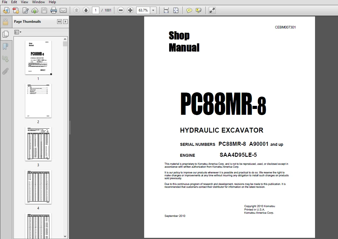
Komatsu PC88MR-8 Hydraulic Excavator Shop Manual
SERIAL NUMBERS : РСЗЗМR-8 А90001 and up
Description
Komatsu PC88MR-8 Hydraulic Excavator Shop Manual
FILE DETAILS:
Komatsu PC88MR-8 Hydraulic Excavator Shop Manual
Brands: Komatsu
Equipment Type: Hydraulic Excavator
Manuals Type: Shop Manual
Machine Model: PC88MR-8
Serial Number: А90001 and up
Book Code: CEBM007301
Language: English
Pages: 1001
File Format: Portable Document Format (PDF)
DESCRIPTION:
Komatsu PC88MR-8 Hydraulic Excavator Shop Manual
FOREWORD:
1 GENERAL :
This shop manual has been prepared as an aid to improve the quality of repairs by giving the serviceman an accurate understanding of the product and by showing him the correct way to perform repairs and make judgements. Make sure you understand the contents of this manual and use it to full effect at every opportunity. This shop manual mainly contains the necessary technical information for operations performed in a service workshop. For ease of understanding, the manual is divided into the following sections. These sections are further divided into each main group of components.
GENERAL:
This section lists the general machine dimensions, performance specifications, component weights, and fuel, coolant and lubricant specification charts.
STRUCTURE, FUNCTION AND MAINTENANCE STANDARD:
This section gives the judgement standards when inspecting disassembled parts. It explains the structure and function of each component. It serves not only to give an understanding of the structure, but also serves as reference material for troubleshooting.
TESTING, ADJUSTING AND TROUBLESHOOTING:
This section explains checks to be made before and after performing repairs, as well as adjustments to be made at completion of the checks and repairs. Troubleshooting charts correlating “Problems” to “Causes” are also included in this section.
DISASSEMBLY AND ASSEMBLY:
This section explains the order to be followed when removing, installing, disassembling or assembling each component, as well as precautions to be taken for these operations.
OTHER:
This section has the foldout drawings for the machine.
TABLE OF CONTENTS:
Komatsu PC88MR-8 Hydraulic Excavator Shop Manual
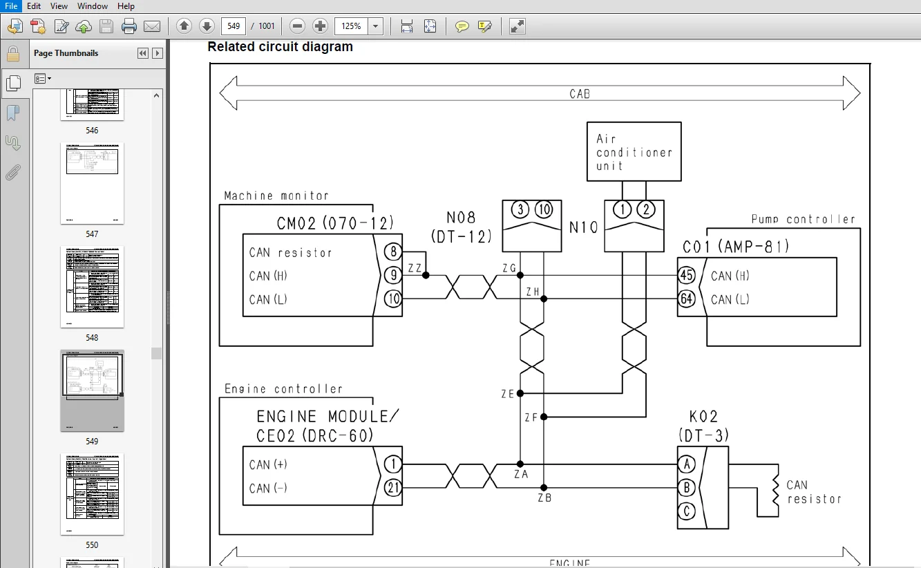
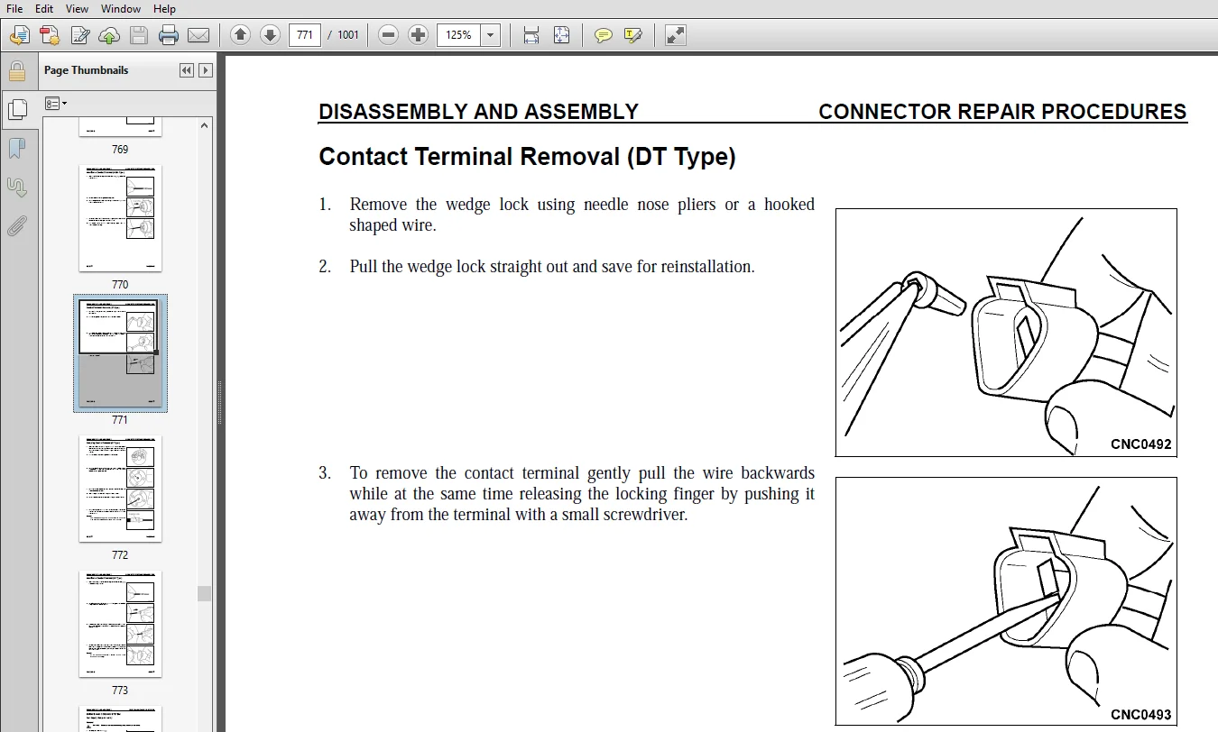
CEBM007301 - PC88MR-8 sn A90001-up...........................................................................   0
	CONTENTS.................................................................................................   2
	REVISED PAGES............................................................................................   3
	SAFETY...................................................................................................  19
		Safety Notice........................................................................................  19
			Important Safety Notice..........................................................................  19
			General Precautions..............................................................................  19
			Preparations For Work............................................................................  19
			Precautions During Work..........................................................................  19
	GENERAL..................................................................................................  22
	HOW TO READ THE SHOP MANUAL..............................................................................  23
		Volumes..............................................................................................  23
		Distribution And Updating............................................................................  23
		Filing Method........................................................................................  23
		Revised Edition Mark.................................................................................  23
		Revisions............................................................................................  23
		Symbols..............................................................................................  23
	HOISTING INSTRUCTIONS....................................................................................  24
		Hoisting.............................................................................................  24
		Wire Ropes...........................................................................................  24
	PUSH PULL COUPLER........................................................................................  25
		Type 1...............................................................................................  25
			Disconnection....................................................................................  25
			Connection.......................................................................................  25
		Type 2...............................................................................................  26
			Disconnection....................................................................................  26
			Connection.......................................................................................  26
		Type 3...............................................................................................  27
			Disconnection....................................................................................  27
			Connection.......................................................................................  27
	EXPLANATION OF MAINTENANCE STANDARD TERMS................................................................  28
	STANDARD TIGHTENING TORQUE...............................................................................  30
		Bolts And Nuts.......................................................................................  30
		Tightening Torque Of Hose Nuts.......................................................................  31
		Tightening Torque Of Split Flange Bolts..............................................................  31
		Tightening Torque For Flared Nuts....................................................................  31
		Tightening Torques For O-ring Boss Piping Joints.....................................................  32
		Table Of Tightening Torques For O-ring Boss Plugs....................................................  32
		Torque Table For Hoses (Taper Seal Type And Face Seal Type)..........................................  32
	ELECTRIC WIRE CODE.......................................................................................  33
		Classification By Thickness..........................................................................  33
		Classification By Color And Code.....................................................................  33
		How To Read Electric Wire Code.......................................................................  34
	CONVERSION TABLES........................................................................................  37
		Method Of Using The Conversion Table.................................................................  37
	COATING MATERIALS........................................................................................  43
01 GENERAL...................................................................................................  45
	SPECIFICATIONS DIMENSION DRAWING.........................................................................  46
		Working Range Diagram................................................................................  47
		Specifications.......................................................................................  48
		Weight Table.........................................................................................  52
	TABLE FOR FUEL, COOLANT AND LUBRICANTS...................................................................  54
		Selection According to Ambient Temperature...........................................................  54
		Mixing Rate of Water and Antifreeze..................................................................  55
10 STRUCTURE, FUNCTION AND MAINTENANCE STANDARD..............................................................  57
	ENGINE AND COOLING SYSTEM................................................................................  62
		Engine Mount.........................................................................................  62
		Cooling System.......................................................................................  64
		Power Take Off (PTO).................................................................................  66
	POWER TRAIN..............................................................................................  67
		Power Train..........................................................................................  67
		Swing Circle.........................................................................................  68
		Swing Machinery......................................................................................  70
	UNDERCARRIAGE AND FRAME..................................................................................  72
		Track Frame..........................................................................................  72
		Idler Cushion........................................................................................  73
		Idler................................................................................................  74
		Track Roller.........................................................................................  76
		Carrier Roller.......................................................................................  77
		Sprocket.............................................................................................  78
		Track Shoe...........................................................................................  80
			City Pad Shoe, Road Liner, Triple Grouser Shoe...................................................  80
			City Pad Shoe, Triple Grouser Shoe...............................................................  83
			Road Liner.......................................................................................  84
	HYDRAULIC SYSTEM.........................................................................................  86
		Hydraulic Equipment Layout Drawing...................................................................  86
		Valve Control........................................................................................  87
		Hydraulic Tank and Filter............................................................................  88
			Oil Filler Cap Breather..........................................................................  89
		Hydraulic Pump.......................................................................................  90
			Model: LPD45+45..................................................................................  90
			Operation of Pump................................................................................  95
			Servo Valve......................................................................................  96
			Control of Delivery..............................................................................  98
			LS Valve.........................................................................................  99
			PC Valve.........................................................................................  99
			Action of Spring................................................................................. 100
			When Pump Pressure (PAVE) is Low................................................................. 100
			When Pump Pressure (PAVE) is High................................................................ 100
			When Swing Gear Pump Pressure Increases or Decreases............................................. 100
			When PC-EPC Valve Operates....................................................................... 100
			When Load is Light............................................................................... 101
			When Load is Heavy............................................................................... 102
			When Balanced.................................................................................... 103
		Control Valve........................................................................................ 104
			10-Spool Valve (EU Specification)................................................................ 104
			Sectional Views.................................................................................. 106
			9-Spool Valve (North America Specification)...................................................... 118
		CLSS................................................................................................. 120
			Outline of CLSS.................................................................................. 120
				Features..................................................................................... 120
				Composition.................................................................................. 120
			Basic principle.................................................................................. 121
				Pump swash plate angle control............................................................... 121
				LS differential pressure (rPLS) and pump swash plate angle................................... 121
				Pressure compensation control................................................................ 122
		Functions and Operation by Valve..................................................................... 124
			Hydraulic Circuit Diagram and the Name of Valves................................................. 124
			9-Spool Valve (North America Specification)...................................................... 125
			Unload Valve..................................................................................... 126
			Merge-Divider Valve.............................................................................. 136
			Introduction of LS Pressure...................................................................... 138
			Travel Valve..................................................................................... 139
			LS Bypass Valve.................................................................................. 140
			LS Select Valve.................................................................................. 142
			Boom RAISE Merge Valve........................................................................... 144
			Pressure compensation valve...................................................................... 147
			Boom hydraulic drift prevention valve............................................................ 148
			Boom regeneration circuit........................................................................ 151
			Travel junction valve............................................................................ 154
			Travel LS Bleed Circuit and Travel Junction Valve................................................ 158
		PPC Valve............................................................................................ 162
			Work Equipment and Swing PPC Valve............................................................... 162
			Travel PPC Valve................................................................................. 168
			Blade and Boom Swing PPC Valve................................................................... 172
		Swing Motor.......................................................................................... 174
			Brake Valve...................................................................................... 178
			Modulating Relief Valve.......................................................................... 180
			Swing Holding Brake.............................................................................. 181
			Reverse Prevention Valve......................................................................... 182
		Travel Motor......................................................................................... 185
		Center Swivel Joint.................................................................................. 193
		Solenoid Valve....................................................................................... 194
			4-Spool Solenoid Valve........................................................................... 194
			Check Valve...................................................................................... 195
			Solenoid Valve................................................................................... 196
			EPC Valve........................................................................................ 198
		PPC Accumulator...................................................................................... 201
		Anti-Drop Valve...................................................................................... 203
		Multi-Control Valve.................................................................................. 208
	WORK EQUIPMENT........................................................................................... 209
		Dimensions of Components............................................................................. 212
			Arm.............................................................................................. 212
			Bucket........................................................................................... 216
		Work Equipment Cylinder.............................................................................. 218
			Boom Cylinder.................................................................................... 218
			Arm Cylinder..................................................................................... 218
			Bucket Cylinder.................................................................................. 218
			Boom Swing Cylinder.............................................................................. 219
			Blade Cylinder................................................................................... 219
	AIR CONDITIONER.......................................................................................... 222
		Air Conditioner Piping Diagram....................................................................... 222
			Refrigerant Circuit Diagram...................................................................... 224
		Air Conditioner Unit................................................................................. 226
			Air Conditioner Controller....................................................................... 229
		Compressor........................................................................................... 230
		Condenser............................................................................................ 231
		Receiver............................................................................................. 232
		Sensors.............................................................................................. 233
			Sunlight Sensor.................................................................................. 233
			Ambient Air Temperature Sensor................................................................... 233
	ELECTRICAL SYSTEM........................................................................................ 234
		Electrical Control System............................................................................ 234
			Machine Control System Diagram................................................................... 234
			Engine Control Function.......................................................................... 236
			Engine and Pump Mutual Control Function.......................................................... 238
			Auto-Deceleration Function....................................................................... 242
			Engine Automatic Warm-Up Function................................................................ 244
			Turbocharger Protection Function................................................................. 246
			Swing Control Function........................................................................... 248
			Travel Control Function.......................................................................... 250
			PPC Lock Function................................................................................ 252
			Oil Flow Adjuster Function for Attachment........................................................ 253
		System Components.................................................................................... 254
			Engine Controller................................................................................ 254
			Pump Controller.................................................................................. 256
			Fuel control dial................................................................................ 258
			Resistor......................................................................................... 259
			Engine Oil Pressure Switch....................................................................... 260
			PPC Oil Pressure Switch.......................................................................... 261
		Monitor System....................................................................................... 262
			Machine monitor.................................................................................. 264
			Display.......................................................................................... 266
			Switches......................................................................................... 270
		Operator Mode Function............................................................................... 274
			Service Mode Function............................................................................ 276
		KOMTRAX System....................................................................................... 277
			KOMTRAX terminal................................................................................. 278
			Input and Output Signals......................................................................... 278
		Sensor............................................................................................... 279
			Atmospheric Pressure Sensor...................................................................... 279
			Boost Pressure and Temperature Sensor............................................................ 279
			Coolant Temperature Sensor....................................................................... 280
			Crankshaft Speed Sensor.......................................................................... 280
			Camshaft Speed Sensor............................................................................ 280
			Common Rail Pressure Sensor...................................................................... 281
			Hydraulic Oil Temperature Sensor................................................................. 281
			Fuel Level Sensor................................................................................ 282
			Pump Oil Pressure Sensor......................................................................... 283
			Boom Cylinder Bottom Oil Pressure Sensor......................................................... 283
			PPC Oil Pressure Sensor.......................................................................... 284
20 STANDARD VALUE TABLES..................................................................................... 285
	STANDARD VALUE TABLE FOR ENGINE RELATED PARTS............................................................ 286
	STANDARD VALUE TABLE FOR CHASSIS......................................................................... 287
30 TESTING AND ADJUSTING..................................................................................... 295
	TOOLS FOR TESTING, ADJUSTING, AND TROUBLESHOOTING........................................................ 298
	ENGINE SPEED............................................................................................. 303
	EXHAUST TEMPERATURE...................................................................................... 304
	EXHAUST GAS COLOR........................................................................................ 306
	VALVE CLEARANCE.......................................................................................... 308
	COMPRESSION PRESSURE..................................................................................... 310
	BLOW-BY PRESSURE......................................................................................... 312
	ENGINE OIL PRESSURE...................................................................................... 314
	HANDLING FUEL SYSTEM PARTS............................................................................... 316
		Releasing Residual Pressure From Fuel System......................................................... 316
		Testing Fuel Pressure................................................................................ 317
		Testing Fuel Return Rate And Fuel Leakage............................................................ 318
		Bleeding Air From Fuel Circuit....................................................................... 320
		Checking Fuel Circuit for Leakage.................................................................... 322
	ALTERNATOR BELT TENSION.................................................................................. 324
		Testing.............................................................................................. 324
		Adjusting............................................................................................ 325
	AIR CONDITIONER COMPRESSOR BELT TENSION.................................................................. 326
		Checking............................................................................................. 326
		Adjusting............................................................................................ 326
	SWING CIRCLE BEARING CLEARANCE........................................................................... 327
	TRACK SHOE TENSION....................................................................................... 328
		Checking............................................................................................. 328
		Adjusting............................................................................................ 328
			Increasing tension............................................................................... 328
			Decreasing tension............................................................................... 329
	OIL PRESSURE IN WORK EQUIPMENT AND TRAVEL CIRCUITS....................................................... 330
		Testing.............................................................................................. 330
		Adjusting............................................................................................ 332
	SWING AND BLADE CIRCUIT OIL PRESSURE..................................................................... 334
		Testing.............................................................................................. 334
	CONTROL CIRCUIT BASIC PRESSURE........................................................................... 338
	OIL PRESSURE IN PUMP PC CONTROL CIRCUIT.................................................................. 340
	PC-EPC SOLENOID OUTPUT PRESSURE.......................................................................... 343
	LS DIFFERENTIAL PRESSURE AND LS VALVE.................................................................... 344
		Testing LS Differential Pressure..................................................................... 344
		Adjusting LS Valve................................................................................... 345
	SOLENOID VALVE OUTPUT PRESSURE........................................................................... 346
	PPC VALVE OUTPUT PRESSURE................................................................................ 348
	PLAY OF WORK EQUIPMENT AND SWING PPC VALVES.............................................................. 350
	PARTS WHICH CAUSE HYDRAULIC DRIFT OF WORK EQUIPMENT...................................................... 352
	TRAVEL DEVIATION......................................................................................... 354
		Inspection........................................................................................... 354
		Adjusting............................................................................................ 355
	RELEASING RESIDUAL PRESSURE FROM HYDRAULIC CIRCUIT....................................................... 356
	OIL LEAKAGE.............................................................................................. 358
		Bleeding Air from Each Part.......................................................................... 362
	MIRRORS.................................................................................................. 364
	SPECIAL FUNCTIONS OF MACHINE MONITOR..................................................................... 366
		Upper Section of Machine Monitor (Display Section)................................................... 367
		Upper Section of Machine Monitor (Switch Section).................................................... 367
		Lower Section of Machine Monitor (Switch Section).................................................... 367
		Ordinary and Special Functions of Machine Monitor.................................................... 368
			Operator Mode (Outline).......................................................................... 369
			Service Mode..................................................................................... 382
	HANDLING VOLTAGE CIRCUIT OF ENGINE CONTROLLER............................................................ 420
	PREPARATION WORK FOR TROUBLESHOOTING OF ELECTRICAL SYSTEM................................................ 421
		Machine Monitor...................................................................................... 421
		Engine Controller.................................................................................... 422
		Pump Controller...................................................................................... 422
		KOMTRAX Communication Module......................................................................... 423
		Engine Ne Speed Sensor (Crank Sensor)................................................................ 423
		Engine Bkup Speed Sensor (Cam Sensor)................................................................ 423
		Engine Oil Pressure Switch (Oil Pressure Switch)..................................................... 423
		Boost Pressure and Temperature Sensor (Boost Press and Imt).......................................... 424
		Supply Pump IMV Solenoid (Fuel Regulator)............................................................ 424
		Common Rail Pressure Sensor (Fuel Rail Press)........................................................ 425
		Engine Coolant Temperature Sensor (Coolant Temp)..................................................... 425
	PROCEDURE FOR TESTING DIODES............................................................................. 426
		When Using Digital Circuit Tester.................................................................... 426
		When Using Analog Circuit Tester..................................................................... 427
	PM CLINIC SERVICE........................................................................................ 428
		Max. range of engine coolant temperature gauge Max. range of hydraulic oil temperature gauge......... 428
		Check sheet (PC88MR-8)............................................................................... 429
		Engine............................................................................................... 429
		Work equipment speed................................................................................. 429
		Hydraulic drift of work equipment.................................................................... 429
		Hydraulic circuit.................................................................................... 430
		* Gauge changing work: Change hoses of gauges [3] and [4]............................................ 430
		* Gauge changing work: Change [3] and [4] to 60K and change hoses of [3], [4], and [5]............... 431
40 TROUBLESHOOTING........................................................................................... 433
	GENERAL INFORMATION ON TROUBLESHOOTING................................................................... 438
		Points to Remember When Troubleshooting.............................................................. 438
		Sequence of Events in Troubleshooting................................................................ 440
		Checks Before Troubleshooting........................................................................ 441
		Classification and Procedures for Troubleshooting.................................................... 442
			Procedure for Troubleshooting.................................................................... 442
		Phenomena Looking Like Troubles and Troubleshooting Nos.............................................. 444
	CONNECTION TABLE FOR CONNECTOR PIN NUMBERS............................................................... 447
	T-ADAPTER TABLE.......................................................................................... 470
	FAILURE CODE TABLE....................................................................................... 474
	FUSE LOCATIONS........................................................................................... 476
	TROUBLESHOOTING BY FAILURE CODE.......................................................................... 479
		Failure Code [989L00] Engine Controller Lock Caution 1............................................... 479
		Failure Code [989M00] Engine Controller Lock Caution 2............................................... 480
		Failure Code [989N00] Engine Controller Lock Caution 3............................................... 481
		Failure Code [AB00KE] Charge Voltage Low............................................................. 482
		Failure Code [B@BAZG] Eng Oil Press. Low............................................................. 484
		Failure Code [B@BCNS] Eng Coolant Overheat........................................................... 484
		Failure Code [B@HANS] Hyd. Oil Overheat.............................................................. 485
		Failure Code [CA111] ECM Critical Internal Failure................................................... 486
		Failure Code [CA115] Eng. Ne and Bkup Speed Sensor Error............................................. 489
		Failure Code [CA122] Charge Air Press Sensor High Error.............................................. 490
		Failure Code [CA123] Charge Air Press Sensor Low Error............................................... 492
		Failure Code [CA131] Throttle Sensor High Error...................................................... 494
		Failure Code [CA132] Throttle Sensor Low Error....................................................... 496
		Failure Code [CA144] Coolant Temp. Sensor High Error................................................. 498
		Failure Code [CA145] Coolant Temp. Sensor Low Error.................................................. 500
		Failure Code [CA153] Charge Air Temp. Sensor High Error.............................................. 502
		Failure Code [CA154] Charge Air Temp. Sensor Low Error............................................... 504
		Failure Code [CA187] Sensor Sup. 2 Volt. Low Error................................................... 505
		Failure Code [CA221] Ambient Air Press. Sensor High Error............................................ 506
		Failure Code [CA227] Sensor Sup. 2 Volt. High Error.................................................. 509
		Failure Code [CA234] Eng. Overspeed.................................................................. 510
		Failure Code [CA238] Ne Speed Sensor Sup. Volt. Error................................................ 512
		Failure Code [CA272] IMV/PCV1 Open Error............................................................. 516
		Failure Code [CA322] Injector #1 (L #1) System Open/Short Error...................................... 518
		Failure Code [CA324] Injector #3 (L #3) System Open/Short Error...................................... 520
		Failure Code [CA331] Injector #2 (L #2) System Open/Short Error...................................... 522
		Failure Code [CA332] Injector #4 (L #4) System Open/Short Error...................................... 524
		Failure Code [CA351] Inj. Drive Circuit Error........................................................ 526
		Failure Code [CA352] Sensor Sup. 1 Volt. Low Error................................................... 529
		Failure Code [CA386] Sensor Sup. 1 Volt. High Error.................................................. 530
		Failure Code [CA435] Abnormality in Engine Oil Pressure Switch....................................... 532
		Failure Code [CA441] Battery Voltage Low Error....................................................... 533
		Failure Code [CA442] Battery Voltage High Error...................................................... 534
		Failure Code [CA449] Rail Press. Very High Error..................................................... 535
		Failure Code [CA451] Rail Press. Sensor High Error................................................... 536
		Failure Code [CA452] Rail Press. Sensor Low Error.................................................... 538
		Failure Code [CA553] Rail Press. High Error.......................................................... 538
		Failure Code [CA559] Rail Press. Low Error........................................................... 539
		Failure Code [CA731] Eng. Bkup Speed Sensor Phase Error.............................................. 544
		Failure Code [CA757] All Persistent Data Lost Error.................................................. 545
		Failure Code [CA778] Eng. Bkup Speed Sensor Error.................................................... 546
		Failure Code [CA1633] KOMNET Datalink Timeout Error.................................................. 548
		Failure Code [CA2185] Throttle Sens. Sup. Volt. High Error........................................... 550
		Failure Code [CA2186] Throttle Sens. Sup. Volt. Low Error............................................ 552
		Failure Code [CA2249] Rail Press. Very Low Error..................................................... 553
		Failure Code [CA2311] Abnormality in IMV Solenoid.................................................... 554
		Failure Code [D110KB] Battery Relay Drive Short...................................................... 556
		Failure Code [D19JKZ] Personal Code Relay Abnormality................................................ 558
		Failure Code [D862KA] GPS Antenna Discon............................................................. 560
		Failure Code [DA22KK] Pump Solenoid Power Low Error.................................................. 562
		Failure Code [DA25KP] 5 V Sensor 1 Power Abnormality................................................. 564
		Failure Code [DA26KP] 5 V Sensor 2 Power Abnormality................................................. 567
		Failure Code [DA2RMC] CAN Discon (Pump Controller Detected).......................................... 568
		Failure Code [DAFGMC] GPS Module Error............................................................... 570
		Failure Code [DAFRMC] CAN Discon (Monitor Detected).................................................. 572
		Failure Code [DFB1KZ] Service Lever Pot. 1 Abnormality............................................... 574
		Failure Code [DFB2KZ] Service Lever Pot. 2 Abnormality............................................... 576
		Failure Code [DFB3L8] Service Lever 1 Potentio Error................................................. 578
		Failure Code [DFB4L8] Service Lever 2 Potentio Error................................................. 580
		Failure Code [DFB5KZ] Service Lever sPot. 1 Abnormality.............................................. 582
		Failure Code [DFB6KZ] Service Lever sPot. 2 Abnormality.............................................. 584
		Failure Code [DGH2KB] Hydr Oil Sensor Short.......................................................... 586
		Failure Code [DHPAMA] Pump Press Sensor Abnormality.................................................. 588
		Failure Code [DHS5KX] Travel PPC Sensor Abnormality.................................................. 590
		Failure Code [DHSAMA] Swing RH PPC Press Sensor Abnormality.......................................... 592
		Failure Code [DHSBMA] Swing LH PPC Press Sensor Abnormality.......................................... 594
		Failure Code [DHX1MA] Overload Sensor Abnormality.................................................... 596
		Failure Code [DV20KB] Travel Alarm Short Circuit..................................................... 598
		Failure Code [DW43KA] Travel Speed Sol Discon........................................................ 600
		Failure Code [DW43KB] Travel Speed Sol Short......................................................... 601
		Failure Code [DW45KA] Swing Brake Sol Discon......................................................... 602
		Failure Code [DW45KB] Swing Brake Sol Short.......................................................... 604
		Failure Code [DWJ0KA] Merge-Divider Sol Discon....................................................... 606
		Failure Code [DWJ0KB] Merge-Divider Sol Short........................................................ 607
		Failure Code [DXA8KA] PC-EPC Sol Discon.............................................................. 608
		Failure Code [DXA8KB] PC-EPC Sol Short............................................................... 610
		Failure Code [DXE7KA] Service Current EPC2 Open Circuit.............................................. 612
		Failure Code [DXE7KB] Service Current EPC2 Short Circuit............................................. 614
		Failure Code [DXE8KA] Service Current EPC3 Open Circuit.............................................. 616
		Failure Code [DXE8KB] Service Current EPC3 Short Circuit............................................. 618
		Failure Code [DXE9KA] Service Current EPC4 Open Circuit.............................................. 620
		Failure Code [DXE9KB] Service Current EPC4 Short Circuit............................................. 622
		Failure Code [DXEAKA] Service Current EPC1 Open Circuit.............................................. 624
		Failure Code [DXEAKB] Service Current EPC1 Short Circuit............................................. 626
		Failure Code [DY20KA] Wiper Working Abnormality...................................................... 628
		Failure Code [DY20MA] Wiper Parking Abnormality...................................................... 630
		Failure Code [DY2CKA] Washer Drive Open Circuit...................................................... 632
		Failure Code [DY2CKB] Washer Drive Short Circuit..................................................... 634
		Failure Code [DY2DKB] Wiper Drive (FWD) Short Circuit................................................ 636
		Failure Code [DY2EKB] Wiper Drive (REV) Short Circuit................................................ 638
	TROUBLESHOOTING OF ELECTRICAL SYSTEM (E-MODE)............................................................ 640
		Before Carrying Out Troubleshooting of Electrical System............................................. 640
			Connection table of fuse box..................................................................... 640
			Locations of fusible links....................................................................... 641
			Location of fuse box and fuse numbers............................................................ 641
		Information in Troubleshooting Table................................................................. 642
		E-1 When Starting Switch is Turned On, Machine Monitor Displays Nothing.............................. 644
		E-2 Engine Does Not Start (Engine Does Not Turn)..................................................... 646
		E-3 Preheater Does Not Operate....................................................................... 649
		E-5 All Work Equipment, Swing, and Travel Mechanism Does Not Move or Cannot Be Locked................ 652
		E-6 Precaution Lights Up While Engine Is Running..................................................... 654
		E-7 Emergency Stop Item Lights Up While Engine Is Running............................................ 657
		E-8 Engine Coolant Temperature Gauge Does Not Indicate Normally...................................... 658
		E-9 Hydraulic oil temperature gauge does not indicate normally....................................... 660
		E-10 Fuel Level Gauge Does Not Indicate Normally..................................................... 663
		E-11 Contents of Display by Machine Monitor are Different From Applicable Machine.................... 665
		E-12 Machine Monitor Does Not Display Some Items..................................................... 665
		E-13 Function Switch Does Not Work................................................................... 665
		E-14 Auto-decelerator Does Not Operate Normally...................................................... 666
		E-15 Working Mode Does Not Change.................................................................... 667
		E-16 Travel Speed Does Not Change.................................................................... 668
		E-17 Alarm Buzzer Cannot Be Stopped.................................................................. 669
		E-18 Windshield Wiper And Window Washer Do Not Operate............................................... 670
		E-19 Swing Holding Brake Does Not Operate Normally................................................... 674
		E-20 Travel Alarm Does Not Sound Or Does Not Stop Sounding........................................... 676
		E-21 Air Conditioner Does Not Operate Normally (Including Air Conditioner Abnormality Record)........ 677
		E-22 While Starting Switch is in Off Position, Service Meter is not Displayed........................ 690
		E-25 Komtrax System Does Not Operate Normally........................................................ 712
	TROUBLESHOOTING OF HYDRAULIC AND MECHANICAL SYSTEM (H-MODE).............................................. 715
		Information Contained in Troubleshooting Table....................................................... 715
		System Chart for Hydraulic and Mechanical Systems.................................................... 717
		H-1 Speed or Power of all Work Equipment, Swing, and Travel are Low.................................. 719
		H-2 Engine Speed Sharply Drops or Engine Stalls...................................................... 720
		H-3 No Work Equipment, Travel and Swing Move......................................................... 721
		H-4 Abnormal Noise is Heard from Around Hydraulic Pump............................................... 721
		H-5 Fine Control Performance or Response of Work Equipment and Travel is Low......................... 722
		H-6 Speed or Power of Boom is Low.................................................................... 723
		H-7 Speed or Power of Arm is Low..................................................................... 724
		H-8 Speed or Power of Bucket is Low.................................................................. 725
		H-9 Speed or Power of Boom Swing is Low.............................................................. 726
		H-10 Speed or Power of Blade is Low.................................................................. 727
		H-11 Work Equipment Does Not Move in its Single Operation............................................ 728
		H-12 Hydraulic Drift of Work Equipment is Large...................................................... 729
		H-13 Time Lag of Work Equipment is Large............................................................. 731
		H-14 Work Equipment Loaded More is Slower During Compound Operation.................................. 731
		H-15 Boom RAISE Speed is Low in Compound Operation of Swing + Boom Raise............................. 731
		H-16 Travel Speed Lowers Significantly During Compound Operation of Work Equipment/Swing + Travel.... 732
		H-17 Machine Deviates During Travel.................................................................. 733
		H-18 Travel Speed is Low............................................................................. 734
		H-19 Machine Cannot be Steered Easily or Steering Power is Low....................................... 735
		H-20 Travel Speed Does Not Change or it is Kept Low or High.......................................... 736
		H-21 Track Does Not Move (Only Either Side).......................................................... 736
		H-22 Machine Does Not Swing.......................................................................... 737
		H-23 Swing Acceleration, Swing Speed and Swing Power are Low......................................... 739
		H-24 Excessive Overrun when Stopping Swing........................................................... 741
		H-25 When Upper Structure Stops Swinging, it Makes Large Shock....................................... 742
		H-26 When Upper Structure Stops Swinging, it Makes Large Sound....................................... 742
		H-27 Hydraulic Drift of Swing is Large............................................................... 743
		H-28 Flow Rate in Attachment Circuit Cannot Be Adjusted.............................................. 744
50 DISASSEMBLY AND ASSEMBLY.................................................................................. 745
	HOW TO READ THIS MANUAL.................................................................................. 750
		Removal and Installation of Assemblies............................................................... 750
			Special Tools.................................................................................... 750
			Removal.......................................................................................... 750
			Installation..................................................................................... 750
		Disassembly and Assembly of Assemblies............................................................... 751
			Special Tools.................................................................................... 751
			Disassembly...................................................................................... 751
			Assembly......................................................................................... 752
	COATING MATERIALS LIST................................................................................... 754
	SPECIAL TOOLS LIST....................................................................................... 758
	SKETCHES OF SPECIAL TOOLS................................................................................ 762
	CONNECTOR REPAIR PROCEDURES.............................................................................. 767
		Stripping Insulation................................................................................. 767
		Wire Inspection...................................................................................... 767
		Contact Terminal Removal (HD30 Type)................................................................. 768
		Crimping Contact Terminal (HD30 Type)................................................................ 769
		Insertion of Contact Terminal (HD30 Type)............................................................ 770
		Contact Terminal Removal (DT Type)................................................................... 771
		Crimping Contact Terminal (DT Type).................................................................. 772
		Insertion of Contact Terminal (DT Type).............................................................. 773
	ENGINE AND COOLING SYSTEM................................................................................ 774
		Fuel Supply Pump Assembly............................................................................ 774
			Removal.......................................................................................... 774
			Installation..................................................................................... 778
		Fuel Injector Assembly............................................................................... 780
			Removal.......................................................................................... 780
			Installation..................................................................................... 784
		Engine Front Seal.................................................................................... 786
			Removal.......................................................................................... 786
			Installation..................................................................................... 787
		Engine Rear Seal..................................................................................... 788
			Removal.......................................................................................... 788
			Installation..................................................................................... 790
		Cylinder Head Assembly............................................................................... 791
			Removal.......................................................................................... 791
			Installation..................................................................................... 801
		Radiator Assembly.................................................................................... 806
			Removal.......................................................................................... 806
			Installation..................................................................................... 809
		Aftercooler Assembly................................................................................. 810
			Removal.......................................................................................... 810
			Installation..................................................................................... 813
		Hydraulic Oil Cooler Assembly........................................................................ 814
			Removal.......................................................................................... 814
			Installation..................................................................................... 817
		Engine and Hydraulic Pump Assembly................................................................... 818
			Removal.......................................................................................... 818
			Installation..................................................................................... 830
		Fuel Tank Assembly................................................................................... 834
			Removal.......................................................................................... 834
			Installation..................................................................................... 836
	POWER TRAIN.............................................................................................. 838
		Travel Motor and Final Drive Assembly................................................................ 838
			Removal.......................................................................................... 838
			Installation..................................................................................... 839
			Swing Motor and Swing Machinery Assembly......................................................... 840
			Installation..................................................................................... 841
			Swing Machinery.................................................................................. 842
			Disassembly...................................................................................... 842
			Assembly......................................................................................... 848
		Swing Circle Assembly................................................................................ 854
			Removal.......................................................................................... 854
			Installation..................................................................................... 855
	UNDERCARRIAGE AND FRAME.................................................................................. 856
		Track Roller Assembly................................................................................ 856
			Disassembly...................................................................................... 856
			Assembly......................................................................................... 858
		Idler Assembly....................................................................................... 862
			Disassembly...................................................................................... 862
			Assembly......................................................................................... 863
		Recoil Spring Assembly............................................................................... 866
			Disassembly...................................................................................... 866
			Assembly......................................................................................... 868
		Track Shoe Assembly.................................................................................. 870
			Spreading........................................................................................ 870
			Installation..................................................................................... 871
		Sprocket............................................................................................. 872
			Removal.......................................................................................... 872
			Installation..................................................................................... 872
		Revolving Frame Assembly............................................................................. 874
			Removal.......................................................................................... 874
			Installation..................................................................................... 876
		Counterweight Assembly............................................................................... 878
			Removal.......................................................................................... 878
			Installation..................................................................................... 883
	HYDRAULIC SYSTEM......................................................................................... 884
		Center Swivel Joint Assembly......................................................................... 884
			Removal.......................................................................................... 884
			Installation..................................................................................... 885
			Disassembly...................................................................................... 886
			Assembly......................................................................................... 887
		Hydraulic Tank Assembly.............................................................................. 888
			Removal.......................................................................................... 888
			Installation..................................................................................... 891
		Hydraulic Pump Assembly.............................................................................. 892
			Removal.......................................................................................... 892
			Installation..................................................................................... 897
		Control Valve Assembly............................................................................... 898
			Removal.......................................................................................... 898
			Disassembly...................................................................................... 908
			Assembly......................................................................................... 908
		Work Equipment PPC Valve Assembly.................................................................... 916
			Disassembly...................................................................................... 916
			Assembly......................................................................................... 916
		Travel PPC Valve Assembly............................................................................ 918
			Assembly......................................................................................... 918
		Boom Swing Cylinder Assembly......................................................................... 920
			Removal.......................................................................................... 920
			Installation..................................................................................... 923
		Hydraulic Cylinder Assembly.......................................................................... 924
			Disassembly...................................................................................... 925
			Assembly......................................................................................... 928
	WORK EQUIPMENT........................................................................................... 932
		Work Equipment Assembly (Machine With Boom Hydraulic Drift Prevention Valve)......................... 932
			Removal.......................................................................................... 932
			Installation..................................................................................... 935
		Boom Swing Bracket................................................................................... 936
			Removal.......................................................................................... 936
			Installation..................................................................................... 939
		Blade Assembly....................................................................................... 940
			Removal.......................................................................................... 940
			Installation..................................................................................... 941
	CAB AND ITS ATTACHMENTS.................................................................................. 942
		Operator Cab Assembly................................................................................ 942
			Removal.......................................................................................... 942
			Installation..................................................................................... 948
		Operator's Cab Glass (Stuck glass)................................................................... 950
			Removal.......................................................................................... 951
			Installation..................................................................................... 952
		Front Window Assembly................................................................................ 961
			Removal.......................................................................................... 961
			Installation..................................................................................... 961
		Floor Frame Assembly................................................................................. 962
			Removal.......................................................................................... 962
			Installation..................................................................................... 969
		Air Conditioner Compressor Assembly.................................................................. 970
			Removal.......................................................................................... 970
			Installation..................................................................................... 971
		Air Conditioner Condenser Assembly................................................................... 972
			Removal.......................................................................................... 972
			Installation..................................................................................... 972
		Air Conditioner Unit Assembly........................................................................ 974
			Removal.......................................................................................... 974
			Installation..................................................................................... 979
	ELECTRICAL SYSTEM........................................................................................ 980
		Machine Monitor Assembly............................................................................. 980
			Removal.......................................................................................... 980
			Installation..................................................................................... 981
		Pump Controller Assembly............................................................................. 982
			Removal.......................................................................................... 982
			Installation..................................................................................... 984
		Engine Controller Assembly........................................................................... 986
			Removal.......................................................................................... 986
			Installation..................................................................................... 989
		KOMTRAX Terminal Assembly............................................................................ 990
			Removal.......................................................................................... 990
			Installation..................................................................................... 990
90 DIAGRAMS AND SCHEMATICS................................................................................... 991
	HYDRAULIC SYSTEM......................................................................................... 993
		Hydraulic Circuit Diagram............................................................................ 993
	ELECTRICAL SYSTEM........................................................................................   0
		Electrical Circuit Diagram (2/6)..................................................................... 995
		Electrical Circuit Diagram (3/6)..................................................................... 996
		Electrical Circuit Diagram (4/6)..................................................................... 997
		Electrical Circuit Diagram (5/6)..................................................................... 998
		Electrical Circuit Diagram (6/6)..................................................................... 999
		Electrical Circuit Diagram for Air Conditioner.......................................................1000
		Connector List and Stereogram........................................................................1001
KOMATSU PC88MR-8 HYDRAULIC EXCAVATOR SHOP MANUAL – PDF DOWNLOAD:
IMAGES PREVIEW OF THE MANUAL:
PLEASE NOTE:
- This is the same manual used by the DEALERSHIPS to SERVICE your vehicle.
- The manual can be all yours – Once payment is complete, you will be taken to the download page from where you can download the manual. All in 2-5 minutes time!!
- Need any other service / repair / parts manual, please feel free to contact us at heydownloadss @gmail.com . We may surprise you with a nice offer


Ulises Musa –
Fast and perfect!