Komatsu WA150-6 Wheel Loader Shop Manual SEN04884-01 – PDF DOWNLOAD
Original price was: $46.95.$26.95Current price is: $26.95.
Komatsu WA150-6 Wheel Loader Shop Manual
SERIAL NUMBERS 80001 and up
Description
Komatsu WA150-6 Wheel Loader Shop Manual SEN04884-01
FILE DETAILS:
Komatsu WA150-6 Wheel Loader Shop Manual
Brands: Komatsu
Equipment Type: Wheel Loader
Manuals Type: Shop Manual
Machine Model: WA150-6
Serial Number: 80001 and up
Book Code: SEN04884-01
Language: English
Pages: 1244
File Format: Portable Document Format (PDF)
DESCRIPTION:
Komatsu WA150-6 Wheel Loader Shop Manual
How to read the shop manual:
1. Composition of shop manual
This shop manual contains the necessary technical information for services performed in a workshop. For ease of understanding, the manual is divided into the following sections.
00. Index and foreword
This section contains the index, foreword, safety and basic information. If any revision is made, the LIST OF REVISED PAGES will be added.
01. Specification:
This section explains the specifications of the machine.
10. Structure and function:
This section explains the structure and function of each component. It serves not only to give an understanding for the structure of each component, but also serves as reference material for troubleshooting.
20. Standard value table:
This section explains the standard values for new machine and judgement criteria for testing, adjusting, and troubleshooting. This standard value table is used to check the standard values in testing and adjusting and to judge parts in troubleshooting.
30. Testing and adjusting:
This section explains measuring tools and measuring methods for testing and adjusting, as well as the adjusting method of each part. The standard values and judgment criteria for “Testing and adjusting” are
explained in “Standard value table”.
40. Troubleshooting:
This section explains how to find out failed parts and how to repair them. The troubleshooting is dividedby failure modes. The “S mode” of the troubleshooting related to the engine may be also explained in the
Chassis volume and Engine volume. In this case, see the Chassis volume.
50. Disassembly and assembly:
This section explains the special tools and procedures for removing, installing, disassembling, and assembling each component, as well as precautions for them. In addition, tightening torque, and quantity and
weight of coating material, oil, grease, and coolant necessary for the work are also explained.
60. Maintenance standard:
This section gives maintenance standard values of each component. The maintenance standard sub-section explains the criteria and remedies for disassembly and service.
80. Appendix:
This section explains the structure, function, testing, adjusting, and troubleshooting for the equipment not classifiable in other sections.
90. Diagrams and drawings (chassis volume) /Repair and replacement of parts (engine volume):
- Chassis volume
This section gives hydraulic circuit diagrams and electrical circuit diagrams. - Engine volume
This section explains the method of remanufacturing and repairing engine and replacing parts.
TABLE OF CONTENTS:
Komatsu WA150-6 Wheel Loader Shop Manual
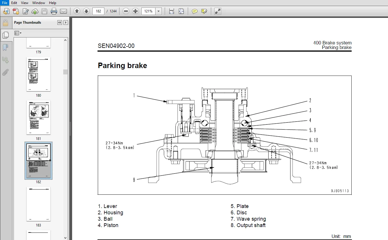
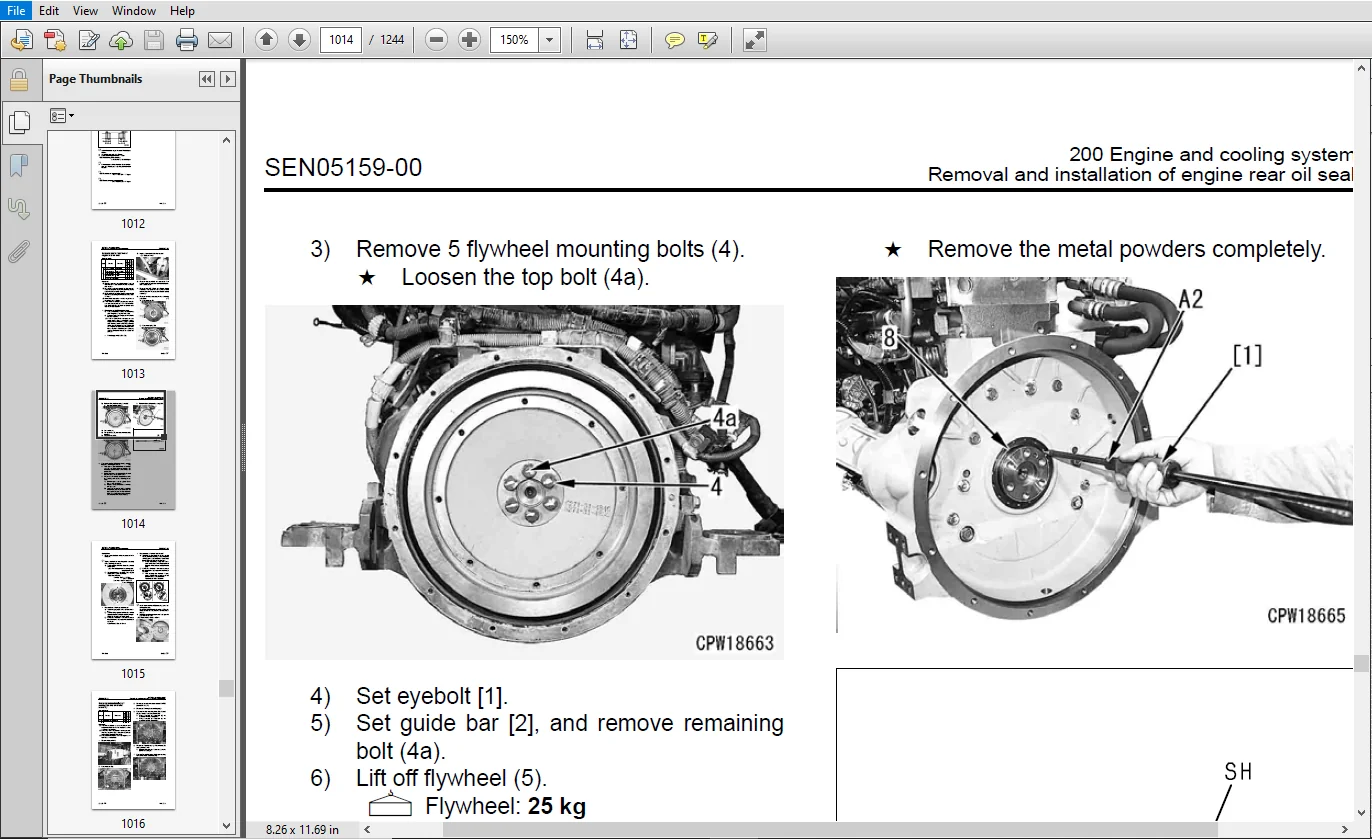
COVER.................................................................................................................................   1
00 Index and foreword.................................................................................................................   3
	100 Index.........................................................................................................................   3
		Composition of shop manual....................................................................................................   4
		Table of contents.............................................................................................................   6
	200 Foreword and general information..............................................................................................  17
		Safety notice.................................................................................................................  18
		How to read the shop manual...................................................................................................  23
		Explanation of terms for maintenance standard.................................................................................  25
		Handling of electric equipment and hydraulic component........................................................................  27
		Handling of connectors newly used for engines.................................................................................  36
		How to read electric wire code................................................................................................  39
		Precautions when carrying out operation.......................................................................................  42
		Method of disassembling and connecting push-pull type coupler.................................................................  45
		Standard tightening torque table..............................................................................................  48
		Conversion table..............................................................................................................  52
01 Specification......................................................................................................................  59
	100 Specification and technical data..............................................................................................  59
		Specification dimension drawing...............................................................................................  61
		Specifications................................................................................................................  62
		Weight table..................................................................................................................  66
		Table of fuel, coolant and lubricants.........................................................................................  68
10 Structure, function and maintenance standard.......................................................................................  71
	100 Engine and cooling system.....................................................................................................  71
		Engine mount and transfer mount...............................................................................................  72
		Damper........................................................................................................................  73
		Cooling system................................................................................................................  74
		Cooling system hydraulic piping diagram.......................................................................................  75
		Cooling fan motor.............................................................................................................  77
	200 Power train...................................................................................................................  87
		Power train...................................................................................................................  89
		Power train system diagram....................................................................................................  90
		Drive shaft...................................................................................................................  92
		HST hydraulic piping diagram..................................................................................................  93
		HST pump......................................................................................................................  94
		HST motor..................................................................................................................... 103
		Transfer...................................................................................................................... 110
		Clutch solenoid valve......................................................................................................... 121
		Axle.......................................................................................................................... 122
		Differential.................................................................................................................. 124
		Torque proportioning differential............................................................................................. 129
		Limited slip differential..................................................................................................... 130
		Final drive................................................................................................................... 134
	300 Steering system............................................................................................................... 139
		Steering piping diagram....................................................................................................... 141
		Steering column............................................................................................................... 142
		Priority valve................................................................................................................ 143
		Orbit-roll valve.............................................................................................................. 146
		Steering cylinder............................................................................................................. 154
		Emergency steering piping diagram............................................................................................. 156
		Emergency steering valve...................................................................................................... 157
	400 Brake system.................................................................................................................. 161
		Brake piping diagram.......................................................................................................... 163
		Charge valve.................................................................................................................. 164
		Brake valve................................................................................................................... 168
		Inching valve................................................................................................................. 172
		Accumulator (for brake)....................................................................................................... 173
		Slack adjuster................................................................................................................ 174
		Brake......................................................................................................................... 176
		Parking brake control......................................................................................................... 181
		Parking brake................................................................................................................. 182
	500 Undercarriage and frame....................................................................................................... 185
		Axle mount and center hinge pin............................................................................................... 186
		Tires......................................................................................................................... 191
	600 Hydraulic system.............................................................................................................. 193
		Hydraulic component layout drawing............................................................................................ 194
		Work equipment control lever linkage.......................................................................................... 196
		Hydraulic tank................................................................................................................ 198
		3-gear pump................................................................................................................... 200
		Work equipment control valve.................................................................................................. 203
		Work equipment PPC valve...................................................................................................... 243
		Attachment PPC valve.......................................................................................................... 250
		Lock valve.................................................................................................................... 252
		2-way restrictor valve........................................................................................................ 253
		Accumulator (for oil cooler circuit).......................................................................................... 254
		Accumulator (for PPC circuit)................................................................................................. 255
		Accumulator (for ECSS)........................................................................................................ 256
	700 Work equipment................................................................................................................ 259
		Work equipment linkage........................................................................................................ 260
		Bucket........................................................................................................................ 262
		Bucket positioner and boom kick-out........................................................................................... 264
		Work equipment cylinder....................................................................................................... 270
	800 Cab and its attachments....................................................................................................... 273
		Cab........................................................................................................................... 275
	901 Electrical system, Part 1..................................................................................................... 277
		Machine monitor system........................................................................................................ 278
		Machine monitor............................................................................................................... 282
	902 Electrical system, Part 2..................................................................................................... 303
		Electrical system (HST controller system)..................................................................................... 304
		HST controller................................................................................................................ 320
		ECSS system................................................................................................................... 321
		KOMTRAX system................................................................................................................ 322
		Engine starting circuit....................................................................................................... 324
		Engine stopping circuit....................................................................................................... 326
		Preheating circuit............................................................................................................ 327
		Engine output derating function............................................................................................... 328
		Automatic warm-up function.................................................................................................... 328
		Parking brake circuit......................................................................................................... 330
		Multi-function knob........................................................................................................... 332
		Sensor........................................................................................................................ 333
20 Standard value table............................................................................................................... 341
	100 Standard service value table.................................................................................................. 341
		Standard service value table for engine....................................................................................... 342
		Standard service value table for chassis...................................................................................... 343
30 Testing and adjusting.............................................................................................................. 351
	101 Testing and adjusting, Part 1................................................................................................. 351
		Tools for testing, adjusting, and troubleshooting............................................................................. 353
		Testing engine speed.......................................................................................................... 358
		Testing exhaust gas color..................................................................................................... 360
		Testing exhaust temperature................................................................................................... 362
		Adjusting valve clearance..................................................................................................... 363
		Testing compression pressure.................................................................................................. 365
		Testing blow-by pressure...................................................................................................... 367
		Testing engine oil pressure................................................................................................... 368
		Testing intake air (boost) pressure........................................................................................... 369
		Handling fuel system equipment................................................................................................ 369
		Releasing residual pressure in fuel system.................................................................................... 370
		Testing fuel pressure......................................................................................................... 371
		Testing fuel return rate and leakage.......................................................................................... 372
		Bleeding air from fuel circuit................................................................................................ 375
		Checking leakage in fuel system............................................................................................... 376
		Handling cylinder cut-out mode operation...................................................................................... 377
		Handling no-injection cranking operation...................................................................................... 377
		Handling controller voltage circuit........................................................................................... 378
		Check of muffler and muffler stack for looseness and damage................................................................... 378
		Check of muffler function..................................................................................................... 379
		Check of installed condition of cylinder head and manifolds................................................................... 379
		Check of engine piping for damage and looseness............................................................................... 380
		Testing and adjusting air conditioner compressor belt tension................................................................. 380
		Testing and adjusting alternator belt tension................................................................................. 381
	102 Testing and adjusting, Part 2................................................................................................. 383
		Checking operating force of accelerator pedal................................................................................. 385
		Checking directional lever.................................................................................................... 386
		Testing and adjusting HST oil pressure........................................................................................ 387
		Testing clutch control pressure............................................................................................... 391
		Testing and adjusting steering wheel.......................................................................................... 392
		Testing and adjusting steering oil pressure................................................................................... 394
		Bleeding air from steering circuit............................................................................................ 396
		Testing hydraulic fan......................................................................................................... 397
		Testing brake pedal........................................................................................................... 399
		Testing and adjusting brake pedal linkage..................................................................................... 400
		Testing brake performance..................................................................................................... 401
		Testing and adjusting accumulator charge pressure............................................................................. 402
		Testing wheel brake oil pressure.............................................................................................. 404
		Testing wear of brake disc.................................................................................................... 407
		Bleeding air from wheel brake circuit......................................................................................... 408
		Releasing residual pressure in brake accumulator circuit...................................................................... 409
		Testing parking brake performance............................................................................................. 410
		Testing and adjusting parking brake control cable............................................................................. 411
		Testing and adjusting parking brake switch.................................................................................... 412
		Testing and adjusting work equipment control lever............................................................................ 413
		Testing and adjusting work equipment hydraulic pressure....................................................................... 414
		Testing work equipment PPC oil pressure....................................................................................... 416
		Bleeding air from hydraulic circuit........................................................................................... 418
		Releasing remaining pressure in hydraulic circuit............................................................................. 418
		Testing and adjusting bucket positioner....................................................................................... 419
		Testing and adjusting boom kick-out switch.................................................................................... 421
		Checking proximity switch operation pilot lamp................................................................................ 422
		Procedure for testing diodes.................................................................................................. 423
		Preparation work for troubleshooting for electric system...................................................................... 425
		Starting KOMTRAX terminal operations.......................................................................................... 429
		Indicator lamps of KOMTRAX terminal........................................................................................... 433
	103 Testing and adjusting, Part 3................................................................................................. 437
		Adjusting replaced, reassembled or added sensor, controller, etc. with machine monitor........................................ 438
		Special functions of machine monitor (EMMS)................................................................................... 440
		Pm clinic inspection chart.................................................................................................... 495
40 Troubleshooting.................................................................................................................... 499
	100 Failure code table and fuse locations......................................................................................... 499
		Failure codes table........................................................................................................... 500
		Fuse locations................................................................................................................ 506
	200 General information on troubleshooting........................................................................................ 511
		Points to remember when troubleshooting....................................................................................... 512
		Sequence of events in troubleshooting......................................................................................... 513
		Testing before troubleshooting................................................................................................ 514
		Classification and procedures of troubleshooting.............................................................................. 515
		Information contained in troubleshooting table................................................................................ 518
		Connection table for connector pin numbers.................................................................................... 520
		T- branch box and T- branch adapter table..................................................................................... 556
	301 Troubleshooting by failure code (Display of code), Part 1..................................................................... 561
		Failure code [2G40ZG] Brake: Oil pressure reduction........................................................................... 562
		Failure code [6091NX] HST filter: Clogging.................................................................................... 564
		Failure code [989FN1] Travel speed: Overrun alarm............................................................................. 565
		Failure code [AB00L6] Alternator R system: Hot short.......................................................................... 566
		Failure code [AB00MA] Alternator R system: Ground fault/Disconnection/Low charge voltage...................................... 568
		Failure code [B@BAZG] Engine: Oil pressure reduction.......................................................................... 570
		Failure code [B@BCNS] Engine: Overheat........................................................................................ 571
		Failure code [B@BCZK] Engine: Low coolant level............................................................................... 572
		Failure code [B@C6NS] Front brake: High oil temperature....................................................................... 574
		Failure code [B@CRNS] HST: High oil temperature............................................................................... 575
	302 Troubleshooting by failure code (Display of code), Part 2..................................................................... 577
		Failure code [CA111] Abnormality in engine controller......................................................................... 579
		Failure code [CA115] Engine Ne or Bkup speed sensor error..................................................................... 582
		Failure code [CA122] Charge pressure sensor high error........................................................................ 584
		Failure code [CA123] Charge pressure sensor low error......................................................................... 586
		Failure code [CA131] Throttle sensor high error............................................................................... 588
		Failure code [CA132] Throttle sensor low error................................................................................ 590
		Failure code [CA144] Coolant sensor high error................................................................................ 592
		Failure code [CA145] Coolant sensor low error................................................................................. 594
		Failure code [CA153] Charge temperature sensor high error..................................................................... 596
		Failure code [CA154] Charge temperature sensor low error...................................................................... 598
		Failure code [CA187] Sensor power supply 2 low error.......................................................................... 599
		Failure code [CA221] Atmospheric pressure sensor high error................................................................... 600
		Failure code [CA222] Atmospheric sensor low error............................................................................. 602
		Failure code [CA227] Sensor power supply 2 high error......................................................................... 603
		Failure code [CA234] Engine overspeed......................................................................................... 605
		Failure code [CA238] Ne speed sensor power supply error....................................................................... 606
		Failure code [CA271] IMV (IMA) Short circuit.................................................................................. 608
		Failure code [CA272] IMV (IMA) Disconnection.................................................................................. 610
		Failure code [CA322] Injector #1 open/short error............................................................................. 612
		Failure code [CA324] Injector #3 open/short error............................................................................. 614
		Failure code [CA331] Injector #2 open/short error............................................................................. 616
		Failure code [CA332] Injector #4 open/short error............................................................................. 618
		Failure code [CA351] Injectors drive circuit error............................................................................ 620
		Failure code [CA352] Sensor power supply 1 low error.......................................................................... 622
		Failure code [CA386] Sensor power supply 1 high error......................................................................... 624
	303 Troubleshooting by failure code (Display of code), Part 3..................................................................... 627
		Failure code [CA431] Idle validation switch error............................................................................. 628
		Failure code [CA432] Idle validation action error............................................................................. 632
		Failure code [CA435] Engine oil pressure switch error......................................................................... 636
		Failure code [CA441] Battery voltage low error................................................................................ 637
		Failure code [CA442] Battery voltage high error............................................................................... 638
		Failure code [CA449] Common rail pressure high error 2........................................................................ 639
		Failure code [CA451] Common rail pressure sensor high error................................................................... 640
		Failure code [CA452] Common rail pressure sensor low error.................................................................... 642
		Failure code [CA553] Common rail pressure high error 1........................................................................ 643
		Failure code [CA559] Supply pump pressure very low error...................................................................... 644
		Failure code [CA689] Engine Ne speed sensor error............................................................................. 648
		Failure code [CA731] Engine Bkup speed sensor phase error..................................................................... 650
		Failure code [CA757] All continuous data lost error........................................................................... 651
		Failure code [CA778] Engine Bkup speed sensor error........................................................................... 652
		Failure code [CA1633] KOMNET datalink timeout error........................................................................... 654
		Failure code [CA2185] Throttle sensor supply voltage high error............................................................... 656
		Failure code [CA2186] Throttle sensor power supply low error.................................................................. 658
		Failure code [CA2249] Supply pump pressure very low error 2................................................................... 660
		Failure code [CA2311] Abnormality in IMV (IMA) solenoid....................................................................... 662
		Failure code [CA2555] Intake heater relay disconnection error................................................................. 664
		Failure code [CA2556] Intake heater relay short circuit error................................................................. 666
	304 Troubleshooting by failure code (Display of code), Part 4..................................................................... 669
		Failure code [D160KY] Backup alarm/lamp relay 1 circuit: Hot short............................................................ 670
		Failure code [D192KY] ECSS solenoid relay: Hot short.......................................................................... 672
		Failure code [D1B0KA] HST safety relay: Disconnection......................................................................... 674
		Failure code [D1B0KB] HST safety relay: Ground fault.......................................................................... 676
		Failure code [D1B0KY] HST safety relay: Hot short............................................................................. 678
		Failure code [D5ZHL6] IGN C system: Ground fault/Disconnection................................................................ 680
		Failure code [DAF3KK] UNSW power supply: Ground fault/Disconnection........................................................... 682
		Failure code [DAFRKR] Machine monitor CAN-NET Signal: Disconnection........................................................... 684
		Failure code [DAJ0KK] HST controller power supply: Low voltage................................................................ 688
		Failure code [DAJ0KT] HST controller memory (EEPROM): Abnormality............................................................. 690
		Failure code [DAJ1L4] HST controller main power line: Disconnection/Ground fault.............................................. 692
		Failure code [DAJ1L6] HST controller main power line: Hot short............................................................... 694
		Failure code [DAJ2KK] Controller solenoid power supply: Low voltage........................................................... 696
		Failure code [DAJ2L3] HST controller load power supply holding line: Hot short in wiring harness.............................. 698
		Failure code [DAJ2L4] HST controller load power supply holding line: Disconnection/Ground fault............................... 700
		Failure code [DAJ5KX] Sensor 5V power supply: Out of output range............................................................. 702
		Failure code [DAJ9KQ] HST controller model selection: Disagreement of model selection signals................................. 704
		Failure code [DAJRKR] HST controller CAN-NET signal: Disconnection............................................................ 705
		Failure code [DAJRMA] HST controller: Disagreement in option selection........................................................ 711
	305 Troubleshooting by failure code (Display of code), Part 5..................................................................... 713
		Failure code [DB2RKR] Engine controller CAN-NET: Disconnection in signal line................................................. 714
		Failure code [DD1NL4] Fan automatic reverse switch signal: Abnormality........................................................ 720
		Failure code [DD1NLD] Fan reverse switch signal: Abnormality.................................................................. 722
		Failure code [DDB6KA] Parking brake reminder signal: Disconnection/Hot short.................................................. 724
		Failure code [DDB6KB] Parking brake indicator signal: Ground fault............................................................ 726
		Failure code [DDB6KZ] Parking brake switch (bottom switch) or parking brake reminder switch (intermediate switch): Trouble.... 728
		Failure code [DDB6L0] Parking brake reminder signal: Ground fault............................................................. 730
		Failure code [DDB6L4] Parking brake indicator signal: Disconnection/Hot short................................................. 732
		Failure code [DDD7KX] Travel speed control dial signal: Disconnection/Ground fault............................................ 734
		Failure code [DDD7KY] Travel speed control dial signal: Hot short............................................................. 736
		Failure code [DDE5MA] Emergency steering operation switch: Disconnection...................................................... 738
		Failure code [DDK3KA] Directional selector switch: Disconnection/Hot short.................................................... 740
		Failure code [DDK3KB] Directional selector switch: Ground fault............................................................... 742
		Failure code [DDK6KA] FNR lever: Disconnection/Ground fault................................................................... 744
		Failure code [DDK6KY] FNR lever: Hot short.................................................................................... 748
		Failure code [DDS5L6] Steering: Low oil pressure (Operation of emergency steering)............................................ 750
	306 Troubleshooting by failure code (Display of code), Part 6..................................................................... 753
		Failure code [DF10KA] Travel speed range selector switch: Disconnection/Ground fault.......................................... 754
		Failure code [DF10KB] Travel speed range selector switch: Hot short........................................................... 758
		Failure code [DGH1KX] HST oil temperature sensor: Ground fault................................................................ 760
		Failure code [DGR2KB] Brake oil temperature sensor: Ground fault.............................................................. 761
		Failure code [DGR2KZ] Brake oil temperature sensor: Disconnection/Hot short................................................... 762
		Failure code [DHH1KX] HST oil pressure sensor: Disconnection/Ground fault..................................................... 764
		Failure code [DHH1KY] HST oil pressure sensor: Hot short...................................................................... 766
		Failure code [DHTCL6] HST filter clogging sensor: Functional defect........................................................... 768
		Failure code [DJF1KA] Fuel level sensor: Disconnection/Hot short.............................................................. 770
		Failure code [DLT3KX] Travel speed sensor B: Abnormality...................................................................... 772
		Failure code [DLT4KX] Travel speed sensor A: Abnormality...................................................................... 776
		Failure code [DLT4LC] Travel speed sensor A & B: Abnormality.................................................................. 778
		Failure code [DV00KY] Alarm buzzer: Hot short................................................................................. 780
		Failure code [DW26KA] Motor 2 solenoid: Disconnection/Ground fault............................................................ 782
		Failure code [DW26KY] Motor 2 solenoid: Hot short............................................................................. 784
		Failure code [DW7BKY] Fan reverse solenoid circuit: Hot short................................................................. 786
		Failure code [DW7BKZ] Fan reverse solenoid circuit: Disconnection/Ground fault................................................ 788
	307 Troubleshooting by failure code (Display of code), Part 7..................................................................... 791
		Failure code [DX16KA] Fan EPC solenoid: Disconnection......................................................................... 792
		Failure code [DX16KB] Fan EPC solenoid: Ground fault.......................................................................... 793
		Failure code [DX16KY] Fan EPC solenoid: Hot short............................................................................. 794
		Failure code [DX19KA] Motor 1 solenoid: Disconnection......................................................................... 796
		Failure code [DX19KB] Motor 1 solenoid: Ground fault.......................................................................... 798
		Failure code [DX19KY] Motor 1 solenoid: Hot short............................................................................. 800
		Failure code [DX20KA] Clutch EPC solenoid: Disconnection...................................................................... 802
		Failure code [DX20KB] Clutch EPC solenoid: Ground fault....................................................................... 804
		Failure code [DX20KY] Clutch EPC solenoid: Hot short.......................................................................... 806
		Failure code [DXH7KB] Reverse solenoid: Ground fault.......................................................................... 808
		Failure code [DXH7KZ] Reverse solenoid: Disconnection/Hot short............................................................... 810
		Failure code [DXH8KB] Forward solenoid: Ground fault.......................................................................... 812
		Failure code [DXH8KZ] Forward solenoid: Disconnection/Hot short............................................................... 814
		Failure code [J141N1] Steering pump: Overrun alarm............................................................................ 816
		Failure code [M100N1] HST pump: Overrun alarm................................................................................. 816
		Failure code [M400N1] Motor 1: Overrun alarm.................................................................................. 817
	400 Troubleshooting of electrical system (E-mode)................................................................................. 819
		E-1 Engine does not start..................................................................................................... 821
		E-2 Preheater does not operate normally....................................................................................... 828
		E-3 Travel speed is low or high............................................................................................... 832
		E-4 ECSS does not operate..................................................................................................... 838
		E-5 ECSS keeps operating...................................................................................................... 841
		E-6 Defective boom kick-out function and cancellation......................................................................... 844
		E-7 Defective bucket positioner function and cancellation..................................................................... 848
		E-8 Defective lift arm FLOATING holding function and cancellation............................................................. 852
		E-9 Travel direction selection system does not function....................................................................... 856
		E-10 Fan does not reverse..................................................................................................... 860
		E-11 Fan keeps rotating in reverse............................................................................................ 864
		E-12 Wiper does not operate................................................................................................... 866
		E-13 Windshield washer does not operate....................................................................................... 870
		E-14 Headlamp, clearance lamp and tail lamp do not light up or go off......................................................... 874
		E-15 Working lamp does not light up or go off................................................................................. 882
		E-16 Turn signal lamp and hazard lamp do not light up or go off............................................................... 887
		E-17 Brake lamp does not light or it keeps lighting up........................................................................ 894
		E-18 Backup lamp does not light or it keeps lighting up....................................................................... 896
		E-19 Backup alarm does not sound or it keeps sounding......................................................................... 899
		E-20 Horn does not sound or it keeps sounding................................................................................. 902
		E-21 Alarm buzzer does not sound or it keeps sounding......................................................................... 904
		E-22 The KOMTRAX system does not work properly................................................................................ 906
	500 Troubleshooting of hydraulic and mechanical system (H-mode)................................................................... 909
		Method of using troubleshooting chart......................................................................................... 911
		Failure code and cause table.................................................................................................. 914
		H-1 The machine does not start................................................................................................ 916
		H-2 The travel speed is slow.................................................................................................. 917
		H-3 The traction force is weak................................................................................................ 918
		H-4 Engine stalls when traveling or engine speed drops excessively............................................................ 919
		H-5 Speed range is not shifted................................................................................................ 920
		H-6 The steering wheel does not turn.......................................................................................... 921
		H-7 The steering wheel is heavy............................................................................................... 922
		H-8 Steering wheel shakes or jerks............................................................................................ 923
		H-9 Machine deviates naturally to one side when traveling..................................................................... 923
		H-10 The brake does not work or does not work well............................................................................ 924
		H-11 The brake is not released or is dragged.................................................................................. 925
		H-12 The lift arm does not rise or lower...................................................................................... 926
		H-13 The lift arm moves slowly or the lift arm rising force is insufficient................................................... 927
		H-14 When rising, the lift arm comes to move slowly at specific height........................................................ 928
		H-15 The lift arm cylinder cannot hold down the bucket (The bucket rises above the ground).................................... 928
		H-16 Hydraulic drifts of the lift arm occur often............................................................................. 928
		H-17 The lift arm wobbles during operation.................................................................................... 928
		H-18 When the control lever is switched from “HOLD” to “RAISE,” the lift arm falls temporarily................................ 929
		H-19 The bucket does not tilt back............................................................................................ 930
		H-20 The bucket moves slowly or the tilting-back force is insufficient........................................................ 931
		H-21 The bucket comes to operate slowly in the midst of tilting-back.......................................................... 932
		H-22 The bucket cylinder cannot hold down the bucket.......................................................................... 932
		H-23 Hydraulic drifts of the bucket occur often............................................................................... 932
		H-24 The bucket wobbles during travel with load (The work equipment valve is set to “HOLD”)................................... 932
		H-25 When the control lever is switched from “HOLD” to “TILT,” the bucket falls temporarily................................... 933
		H-26 The control levers of the lift arm and bucket do not move smoothly and heavy............................................. 933
		H-27 The ECSS does not operate and machine pitches and bounces................................................................ 934
		H-28 Fan revolution is abnormal (Fan sound/vibration is abnormally large or engine overheats)................................. 935
	600 Troubleshooting of engine (S-mode)............................................................................................ 937
		Method of using troubleshooting charts........................................................................................ 938
		S-1 Starting performance is poor.............................................................................................. 942
		S-2 Engine does not start..................................................................................................... 943
		S-3 Engine does not pick up smoothly.......................................................................................... 946
		S-4 Engine stops during operations............................................................................................ 947
		S-5 Engine does not rotate smoothly........................................................................................... 948
		S-6 Engine lacks output (or lacks power)...................................................................................... 949
		S-7 Exhaust smoke is black (incomplete combustion)............................................................................ 950
		S-8 Oil consumption is excessive (or exhaust smoke is blue)................................................................... 951
		S-9 Oil becomes contaminated quickly.......................................................................................... 952
		S-10 Fuel consumption is excessive............................................................................................ 953
		S-11 Oil is in coolant (or coolant spurts back or coolant level goes down).................................................... 954
		S-12 Oil pressure drops....................................................................................................... 955
		S-13 Oil level rises (Entry of coolant or fuel)............................................................................... 956
		S-14 Coolant temperature becomes too high (overheating)....................................................................... 957
		S-15 Abnormal noise is made................................................................................................... 958
		S-16 Vibration is excessive................................................................................................... 959
50 Disassembly and assembly........................................................................................................... 961
	100 General information on disassembly and assembly............................................................................... 961
		How to read this manual....................................................................................................... 962
		Coating materials list........................................................................................................ 964
		Special tools list............................................................................................................ 967
		Sketches of special tools..................................................................................................... 970
	200 Engine and cooling system..................................................................................................... 977
		Removal and installation of fuel supply pump assembly......................................................................... 978
		Removal and installation of fuel injector assembly............................................................................ 982
		Removal and installation of engine hood assembly.............................................................................. 986
		Removal and installation of cylinder head assembly............................................................................ 988
		Removal and installation of radiator.......................................................................................... 998
		Removal and installation of air aftercooler...................................................................................1001
		Removal and installation of hydraulic oil cooler assembly.....................................................................1003
		Removal and installation of engine and HST pump and 3-gear pump assembly......................................................1005
		Removal and installation of engine front oil seal.............................................................................1010
		Removal and installation of engine rear oil seal..............................................................................1013
		Removal and installation of cooling fan and fan motor assembly................................................................1016
		Removal and installation of fuel tank assembly................................................................................1019
	300 Power train...................................................................................................................1025
		Removal and installation of transfer and HST motor assembly...................................................................1026
		Disassembly and assembly of transfer assembly.................................................................................1029
		Removal and installation of parking brake assembly............................................................................1049
		Disassembly and assembly of parking brake assembly............................................................................1050
		Removal and installation of front axle assembly...............................................................................1054
		Removal and installation of rear axle assembly................................................................................1056
		Disassembly and assembly of axle housing assembly.............................................................................1058
		Disassembly and assembly of differential assembly.............................................................................1069
	400 Undercarriage and frame.......................................................................................................1093
		Removal and installation of center hinge pin..................................................................................1094
		Removal and installation of counterweight.....................................................................................1102
	500 Hydraulic system..............................................................................................................1105
		Removal and installation of transfer and HST pump and 3-gear pump assembly....................................................1106
		Removal and installation of HST motor 1 assembly..............................................................................1110
		Removal and installation of HST motor 2 assembly..............................................................................1113
		Removal and installation of work equipment control valve assembly.............................................................1115
		Removal and installation of hydraulic tank assembly...........................................................................1118
		Disassembly and assembly of hydraulic cylinder assembly.......................................................................1120
	600 Work equipment................................................................................................................1125
		Removal and installation of work equipment assembly...........................................................................1126
	700 Cab and its attachments.......................................................................................................1135
		Removal and installation of operator's cab and floor frame assembly...........................................................1136
		Removal and installation of operator's cab glass (Stuck glass)................................................................1141
		Removal and installation of air conditioner unit..............................................................................1149
	800 Electrical system.............................................................................................................1157
		Removal and installation of monitor panel.....................................................................................1158
		Removal and installation of engine controller assembly........................................................................1160
		Removal and installation of HST controller assembly...........................................................................1162
		Removal and installation of KOMTRAX terminal assembly.........................................................................1163
80 Appendix...........................................................................................................................1165
	100 Air conditioner...............................................................................................................1165
		Structure and function........................................................................................................1168
			Air conditioner component.................................................................................................1168
			Configuration and function of refrigerating cycle.........................................................................1170
			Outline of refrigerating cycle............................................................................................1171
			Air conditioner unit......................................................................................................1174
			Functions of major components in the air conditioner unit.................................................................1175
			Blower and intake unit....................................................................................................1176
			Compressor................................................................................................................1177
			Condenser.................................................................................................................1178
			Receiver drier............................................................................................................1179
			Air conditioner control panel.............................................................................................1180
		Testing, adjusting and troubleshooting........................................................................................1182
			Caution about refrigerant.................................................................................................1182
			Troubleshooting procedure.................................................................................................1183
			Block diagram and circuit diagram of control system.......................................................................1184
			Detail of air conditioner unit............................................................................................1187
			Arrangement of connector pins.............................................................................................1188
			Part and connector locations..............................................................................................1189
			Testing with self-diagnosis function (indication on control panel)........................................................1191
			Testing temperature control...............................................................................................1192
			Testing Recirc/Fresh changeover...........................................................................................1193
			Testing evaporator temperature sensor electrically........................................................................1195
			Testing relays............................................................................................................1196
			Troubleshooting chart 1...................................................................................................1197
			Troubleshooting chart 2...................................................................................................1198
			Troubleshooting for electrical system (E mode)............................................................................1201
				E-1 Power supply system (Air conditioner does not operate)............................................................1202
				E-2 Compressor or refrigerant system (Air is not cooled)..............................................................1205
				E-3 Blower motor system (No air comes out or air flow is abnormal)....................................................1208
				E-4 Temperature cannot be controlled..................................................................................1211
				E-5 Recirc/Fresh cannot be changed over...............................................................................1214
			Troubleshooting with gauge pressure.......................................................................................1216
			Connection of service tool................................................................................................1218
			Precautions for connecting air conditioner piping.........................................................................1219
			Handling of compressor oil................................................................................................1220
				1. Control of compressor oil..........................................................................................1220
				2. Adding of compressor oil...........................................................................................1220
				3. Compressor replacement.............................................................................................1221
				4. Applying compressor oil for O-ring.................................................................................1221
90 Diagrams and drawings..............................................................................................................1223
	100 Hydraulic diagrams and drawings...............................................................................................1223
		Hydraulic circuit diagram.....................................................................................................1225
	200 Electrical diagrams and drawings..............................................................................................1228
		Common electrical circuit diagram.............................................................................................1230
		Connector list and stereogram.................................................................................................1242
KOMATSU WA150-6 WHEEL LOADER SHOP MANUAL SEN04884-01 – PDF DOWNLOAD:
IMAGES PREVIEW OF THE MANUAL:
PLEASE NOTE:
- This is the SAME exact manual used by your dealers to fix your vehicle.
- The same can be yours in the next 2-3 mins as you will be directed to the download page immediately after paying for the manual.
- Any queries / doubts regarding your purchase, please feel free to contact [email protected]


Cameron Silas –
Rhys Easton –
Fast and easy