
Komatsu WA500-3 Wheel Loader Shop Manual – Serial 50001 & Up – Full PDF Service Guide
Original price was: $39.95.$23.95Current price is: $23.95.
Complete 1,335-page Komatsu WA500-3 wheel loader shop manual covering serial numbers 50001 and up. Includes structure and function, testing and adjusting, disassembly and assembly, maintenance standards, hydraulic and electrical circuit diagrams, troubleshooting, and full specifications for the S6D140E-2 and SA6D140E-3 engines.
Description
File Details
- Manual Type: Shop Manual (Workshop Service Manual)
- Brand: Komatsu
- Model: WA500-3 Wheel Loader
- Serial Number Coverage: 50001 and up
- Engines Covered: S6D140E-2, SA6D140E-3
- Language: English
- Page Count: 1,335
- File Format: PDF
- Document Number: SEBM009014
Chapters Covered
This Komatsu WA500-3 wheel loader shop manual is divided into six major sections, each containing detailed sub-sections for every major system on the machine:
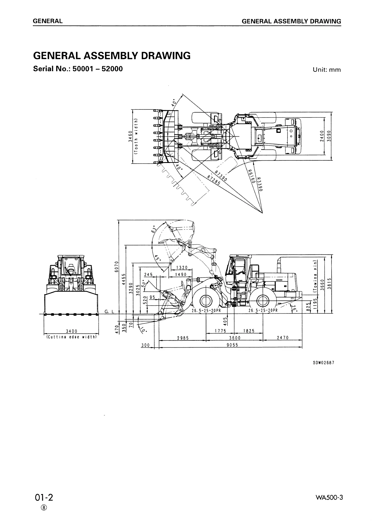
- 01 GENERAL — General assembly drawing, specifications, weight table, list of lubricant and water
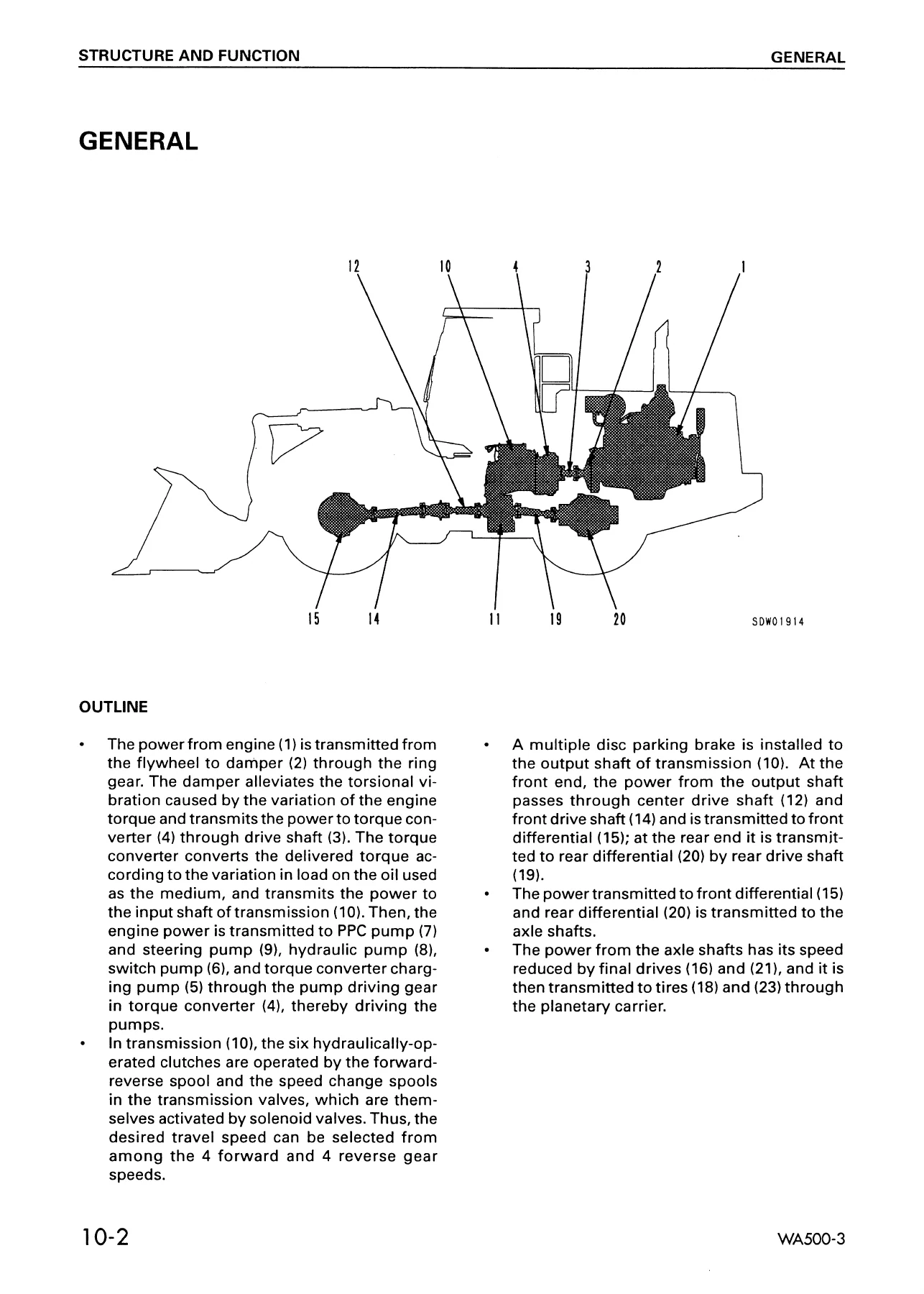
- 10 STRUCTURE AND FUNCTION — Radiator and oil cooler, damper, torque converter and transmission piping, power train hydraulic circuit, torque converter and PTO, transmission, transmission control valve, ECMV, main relief and torque converter relief valve, lubricating relief valve, torque converter oil filter, pilot filter, transfer, drive shaft, center support, axle, differential, limited slip differential, final drive, axle mount, center hinge pin, steering piping, steering column, steering valve, orbit-roll valve, stop valve, diverter valve, brake piping, brake circuit diagram, brake valve, charge valve, accumulator, slack adjuster, brake, parking brake control, parking brake, parking brake solenoid valve, hydraulic piping, hydraulic circuit system, work equipment hydraulic circuit diagram, work equipment lever linkage, hydraulic tank, accumulator (for PPC valve), PPC valve, PPC relief valve, cut-off valve, E.C.S.S. control valve, main control valve, work equipment linkage, bucket, bucket positioner and boom kick-out, operation of proximity switch, cab, ROPS canopy, air conditioner, electric circuit diagram, machine monitor system, main monitor, maintenance monitor, all-range electronic control automatic transmission system, joystick transmission system, E.C.S.S., transmission and E.C.S.S. controller, work equipment control system, remote position joystick steering controller, sensors, engine starting circuit, engine stop circuit, preheating circuit, electric transmission control, kick-down hold switch, kick-down electrical circuit diagram, electric parking brake control
- 20 TESTING AND ADJUSTING — Complete testing and adjustment procedures, troubleshooting of main monitor system (M-Mode), troubleshooting of ECSS (D-Mode), engine controller system error codes (ENG-1 through ENG-29), and related electrical circuit diagrams
- 30 DISASSEMBLY AND ASSEMBLY — Starting motor, alternator, engine oil cooler, fuel injection pump, fuel supply pump, water pump, nozzle holder, fuel injector, turbocharger, engine front seal, engine rear seal, cylinder head, radiator, engine, damper, torque converter, transmission, transfer, parking brake, transmission control valve, center support, drive shaft, front axle, front differential, rear axle, rear differential, differential gear, limited slip differential, final drive, orbit-roll, steering cylinder, steering valve, brake valve, slack adjuster, brake, accumulator charge, hydraulic pump, hydraulic tank, hydraulic filter, PPC valve, main control valve, bucket cylinder, boom cylinder, center hinge pin, work equipment, bulkhead, engine hood, floor frame, counterweight, fuel tank, cab, air conditioner unit, air conditioner condenser, receiver tank, air conditioner compressor
- 40 MAINTENANCE STANDARD — Wear limits, clearances, and adjustment standards for disassembled parts inspection
- 90 OTHERS — Hydraulic circuit diagrams, electric circuit diagrams, and attachment/option specifications
What This Manual Provides
The Komatsu WA500-3 shop manual is the comprehensive technical reference for professional service and repair of the WA500-3 wheel loader. Across 1,335 pages, it delivers the structure and function explanations, testing and adjusting procedures, disassembly and assembly sequences, and maintenance standards needed to correctly diagnose, repair, and overhaul every major system on the machine. The manual covers both engine variants fitted to this model — the S6D140E-2 for serial numbers 50001 through 52000 and the SA6D140E-3 for serial numbers 52001 and up — with dedicated procedures for each where they differ.
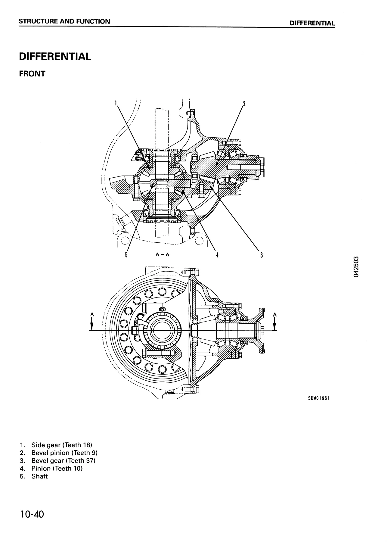
For power train work, the manual details the torque converter, transmission with its planetary gear sets and hydraulically actuated clutches, ECMV (Electronic Control Modulation Valve) operation, transmission control valve, transfer case, drive shafts, center support, axles, differentials (including limited slip), and final drives. Each component is covered with cutaway illustrations, oil flow explanations, and step-by-step disassembly and assembly procedures.
The hydraulic system coverage includes the main control valve, PPC valve, steering valve, orbit-roll valve, diverter valve, charge valve, accumulators, hydraulic tank, filters, and the complete work equipment hydraulic circuit. Full circuit diagrams are provided, with callouts to help trace oil flow through every section of the system.
Brake system coverage spans the brake valve, charge valve, accumulator, slack adjuster, wet disc brakes, parking brake, and parking brake emergency release. Both circuit diagrams and component-level rebuild procedures are included.
Electrical coverage is extensive: the machine monitor system, transmission and E.C.S.S. controller, engine controller system with all error codes, starting and stop circuits, preheating circuit, electric transmission control, kick-down and hold functions, and electric parking brake control. Wiring diagrams are included for every circuit, with wire color codes and connector references.
Troubleshooting is supported by detailed flow charts for the main monitor system (M-Mode), the ECSS system (D-Mode), and the engine controller, with error code tables that explain what each code means, what the controller does when the code is active, and what symptoms the operator will notice. For each error code, the manual provides the specific checks and measurements needed to isolate the fault.
The disassembly and assembly section covers every major component removal and installation, from the engine and transmission down to individual cylinders, valves, and final drives. Each procedure includes tightening torques, special tool requirements, and precautions to prevent damage during handling. The maintenance standard section provides the wear limits and clearances needed to judge whether disassembled parts can be reused or must be replaced.
Why This Manual Matters
Correct service and repair procedures are critical on a machine like the WA500-3. The torque converter, transmission, and hydraulic systems operate at high pressures and precise tolerances — using the wrong procedure, torque value, or assembly sequence can lead to premature failure, costly damage, or unsafe operating conditions. This manual gives the technician the exact specifications and step-by-step methods that Komatsu specifies for the WA500-3, so every repair is done correctly the first time.
For fleet maintenance, having the complete shop manual on hand means fewer delays waiting for information, faster diagnosis of electrical and hydraulic faults, and the confidence that rebuilds are performed to the manufacturer’s standards. The troubleshooting charts alone can save hours of diagnostic time by directing the technician to the most likely causes and the specific tests needed to confirm them.
Delivery
IMAGES PREVIEW
This Komatsu WA500-3 shop manual is delivered as an instant PDF download after payment. There is no shipping, no waiting, and no physical media to lose or damage. The file can be viewed on any device — laptop, tablet, or smartphone — and pages can be printed as needed for use in the workshop. Whether you are servicing one machine or maintaining an entire fleet, this manual provides the complete technical information needed to keep the WA500-3 running reliably.
Reviews
There are no reviews yet.