★ TRUSTED BY 321,897+ PROFESSIONALS WORLDWIDE
🏢
Trusted Business
Verified & Licensed
🛡️
Virus Free Files
100% Safe Downloads
🔒
Secure Payment
SSL Protected
Instant Delivery
Available Immediately
Sale!

Komatsu WA500-6 Wheel Loader Shop Manual SEN00236-19 Serial 55001 and Up

Original price was: $44.95.Current price is: $25.95.

Komatsu WA500-6 shop manual SEN00236-19 for wheel loaders serial 55001 and up: structure, testing, failure-code diagnosis, disassembly, hydraulics, and electrical diagrams for the SAA6D140E-5 machine.

Instant PDF Download
Available immediately
💾
Save to Your Device
Download & keep forever
🛡️
Antivirus Scanned
100% virus-free
🌍
Trusted Worldwide
175,000+ customers

Description

Komatsu WA500-6 Wheel Loader Shop Manual SEN00236-19 Serial 55001 and Up

This Komatsu WA500-6 Wheel Loader Shop Manual SEN00236-19 Serial 55001 and Up is the chassis shop volume used to service the WA500-6 wheel loader from serial number 55001 and up. It walks a technician from specification data through structure and maintenance standards, standard service values, testing and adjusting, failure-code troubleshooting, mechanical and electrical fault charts, and full disassembly and assembly of the major units. The binder form is SEN00236-19; related section forms include SEN00701-19 (index), SEN00702-05 (foreword), SEN00703-03 (specification), and the numbered structure, testing, troubleshooting, and dismantling books listed in the composition table. Copyright on the index form is 2017 Komatsu, printed in Japan 07-17 (01). Cover marking also shows ecoT3.

The shop manual itself states that Komatsu shop manuals are split into a chassis volume and an engine volume. This file is the chassis book for the machine. For complete engine-unit overhaul of the mounted engine, the engine volume for that engine model is required in addition to this chassis volume. Even so, this WA500-6 shop manual still carries chassis-side engine work: cooling-system structure, engine and transmission mounts, compression and blow-by checks, fuel-system handling for the common-rail installation, engine-controller failure codes, S-mode engine troubleshooting charts, and removal of the engine assembly, cylinder head, injectors, supply pump, and front and rear seals.

File Details

  • Manual type: Shop Manual (chassis volume)
  • Brand / model: Komatsu WA500-6 wheel loader
  • Serial range: 55001 and up
  • Engine identified in specification: SAA6D140E-5
  • Language: English
  • Page count: 1864
  • File format: PDF
  • Binder / contents form: SEN00236-19
  • Index form: SEN00701-19
  • Foreword form: SEN00702-05
  • Specification form: SEN00703-03
  • Print note: © 2017 Komatsu, Printed in Japan 07-17 (01)

Machine identity in the specification book

Section 01 records the machine as WA500-6, serial 55001 and up, with an operating weight of 32,230 kg, front wheel load 15,090 kg, and rear wheel load 17,140 kg. Heaped bucket capacity is 5.6 m³ with bolt-on cutting edge; rated load is 9,250 kg. Travel speeds are F1 7.7 km/h, F2 12.5 km/h, F3 22.3 km/h, F4 34.9 km/h and R1 8.6 km/h, R2 13.0 km/h, R3 24.8 km/h, R4 37.5 km/h. Maximum drawbar pull is 288.3 kN {29,400 kg} forward and 256.4 kN {26,150 kg} reverse. Gradeability is 25 degrees. Minimum turning radius at the center of the outside tire is 6,430 mm; turning radius at the bolt-on cutting-edge tip is 7,650 mm.

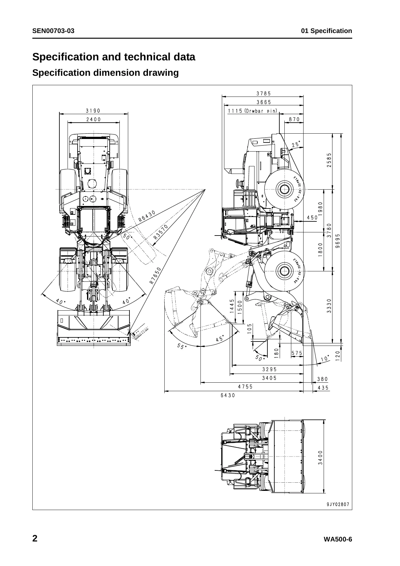
Overall length is 9,815 mm with BOC, overall width 3,190 mm, bucket width 3,400 mm with BOC, overall height at ROPS cab top 3,785 mm, overall height with bucket lifted 6,430 mm, wheelbase 3,780 mm, tread 2,400 mm, and minimum ground clearance 450 mm. Maximum hinge-pin height is 4,755 mm, dumping clearance 3,295 mm with BOC, dumping reach 1,500 mm with BOC, bucket tilt-forward angle 46 degrees, tilt-back angle in operating posture 50 degrees, and digging depth about 435 mm at approximately 10 degrees.

The engine line in the same specification table is SAA6D140E-5: 4-cycle, water-cooled, direct injection, turbocharged, with air-cooled aftercooler and water-cooled EGR. Cylinders, bore and stroke are 6 – 140 x 165 mm. Total piston displacement is 15.2 ℓ {15,240 cc}. Flywheel horsepower is 263 kW / 1,900 rpm {353 HP / 1,900 rpm}. Fuel consumption rate at rated speed is 216.2 g/kWh {161 g/HP·h}. Maximum no-load speed is 2,150 rpm and minimum no-load speed is 675 rpm. Starting motor is 24 V, 11 kW; alternator 24 V, 75 A; batteries 12 V, 170 Ah x 2.

Power train description in that table is a 3-element, 1-stage, 2-phase torque converter; planetary multi-disc transmission with four forward and four reverse speeds; spiral-bevel reduction gear with splash lubrication; straight-bevel differential; and planetary single-reduction final drives with splash lubrication. Drive is front and rear. Front axle is fixed-frame full-float; rear axle is center-pin support full-float. Standard tire size is 29.5-25-33-22PR(L3) on 25.00 x 25WTB rims, inflation 440 kPa {4.5 kg/cm²} front and 392 kPa {4.0 kg/cm²} rear. Foot brakes are independent front and rear enclosed wet multi-disc units; the parking brake is a hydraulically released, spring-applied wet-disc unit on the drive shaft.

IMAGES PREVIEW

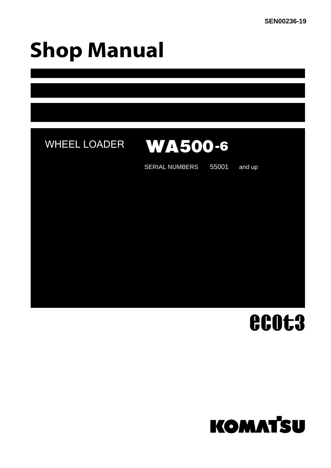
Komatsu WA500-6 Wheel Loader Shop Manual SEN00236-19 Serial 55001 and Up — PDF page 1 preview
Komatsu WA500-6 Wheel Loader Shop Manual SEN00236-19 Serial 55001 and Up — PDF page 62 preview
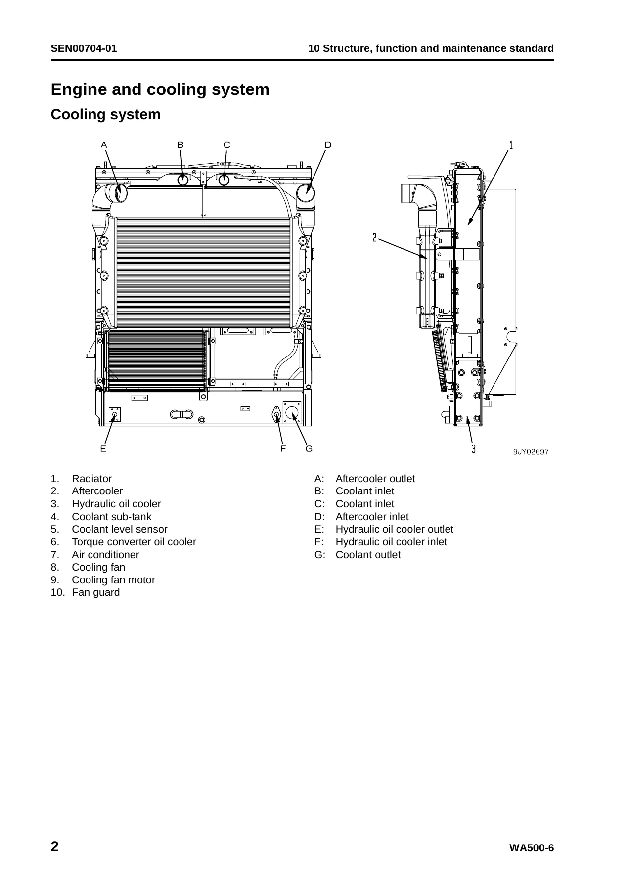
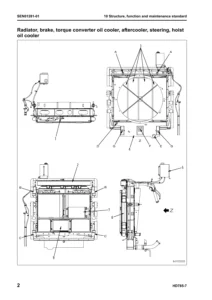
Komatsu WA500-6 Wheel Loader Shop Manual SEN00236-19 Serial 55001 and Up — PDF page 72 preview

Steering is articulated, fully hydraulic. Pump deliveries listed are work equipment HPV190 variable piston pump 321 ℓ/min, steering LPV90 120 ℓ/min, cooling-fan LPV45 70 ℓ/min, power-train gear pump SAR (3) 112 at 189 ℓ/min, hydraulic cooling gear pump SAL (3) 80 at 94 ℓ/min, and EPC and brake gear pump SAR (1) 28 at 54 ℓ/min. Work-equipment set pressure is 34.3 MPa {350 kg/cm²} on the 3-spool valve with HI valve; steering set pressure is 24.5 MPa {250 kg/cm²}. Lift cylinders are two double-acting 160 x 898 mm units; the bucket cylinder is one 185 x 675 mm unit; steering cylinders are two 100 x 486 mm units. Fan motor is fixed-displacement LMF40. Work equipment uses a single link and a straight bolt-on cutting edge.

Fluid capacities in the fuel, coolant and lubricant table are engine oil pan 45 ℓ specified (refill 45 ℓ, 37 ℓ for the pan alone), transmission case 95 ℓ specified / 76 ℓ refill, hydraulic system 460 ℓ specified / 337 ℓ refill, front axle 95 ℓ, rear axle 95 ℓ, cooling system 120 ℓ, and fuel tank 473 ℓ. Recommended fluids include Komatsu engine oils EOS0W30, EOS5W40, EO10W30-DH, EO15W40-DH and EO30-DH, power-train oil TO10, hydraulic oil HO46-HM, axle oil AXO80, greases G2-T / G2-TE / G2-LI, Supercoolant AF-NAC, and ASTM Grade No.1-D / No.2-D S15 and S500 diesel fuels by temperature band.

Chapters Covered

  • 00 Index and foreword — composition of shop manual; table of contents; safety notice; how to read the shop manual; maintenance-standard terms; handling of electric and hydraulic components; engine connectors; electric wire code; operation precautions; push-pull coupler; standard tightening torque; conversion table
  • 01 Specification — specification dimension drawing; specifications; weight table; table of fuel, coolant and lubricants
  • 10 Structure, function and maintenance standard — engine and cooling system (cooling system, mounts, joint, cooling fan pump and motor)
  • Power train, Part 1 — system diagram, drive shaft, piping, torque converter, regulator valve, transmission, transfer, control valve, ECMV, main and torque-converter relief valves, lubrication relief valve
  • Power train, Part 2 — torque converter oil cooler and filter, center support, axle, differential, limited slip differential, final drive
  • Steering system — piping, column, control valve, steering valve, stop valve, joystick linkage if equipped, steering cylinder, emergency steering piping and diverter valve if equipped
  • Brake system — piping, brake valve, slack adjuster, accumulator charge valve, PPC relief valve, brake accumulator, wheel brake, parking brake control, parking brake, solenoid and emergency release valve
  • Undercarriage and frame — axle mount, center hinge pin
  • Hydraulic system, Parts 1 and 2 — piping, lever linkage, tank, steering pump, work equipment pump, control valve, CLSS, valve functions, PPC accumulator, work equipment electric lever
  • Work equipment — linkage, bucket, bucket positioner and boom kick-out, lubrication, cylinders
  • Cab and attachments — ROPS cab, air conditioner
  • Electrical system, Parts 1–3 — machine monitor and EMMS, work equipment control, transmission controller, electric transmission control, starting/stopping/preheat, parking brake, lamps, horn, wiper, sensors, KOMTRAX
  • 20 Standard value table — engine and chassis service-value tables
  • 30 Testing and adjusting, Parts 1–4 — engine measurements, fuel system, belts, power-train pressures, flushing, steering, fan, brakes and accumulators, work equipment PPC and pressures, bucket positioner, KOMTRAX terminal, monitor adjustments, Pm clinic table
  • 40 Troubleshooting — general method; failure codes Parts 1–10; E-mode electrical; H-mode hydraulic and mechanical; S-mode engine
  • 50 Disassembly and assembly — special tools and coatings; engine and cooling; power train and axles; brakes; center hinge pin; hydraulic pumps, valves and cylinders; work equipment and counterweights; cab, glass and seat; controllers, KOMTRAX and air conditioner
  • 90 Diagrams and drawings — automatic greasing, power train, brake and work-equipment hydraulic circuits; air-conditioner and machine electrical circuits; connector arrangement

Taken together, the Komatsu WA500-6 Wheel Loader Shop Manual SEN00236-19 Serial 55001 and Up is the book a shop uses when the machine must be measured, diagnosed, adjusted, or taken apart to the component level. Structure chapters explain how each circuit and unit works and give maintenance-standard clearances. Testing chapters give tool lists, pickup points, and the numbers that belong on a new machine versus the service limit. Troubleshooting is split by displayed failure code, then by E-mode electrical symptoms, H-mode travel/steer/brake/implement complaints, and S-mode engine complaints. Disassembly chapters list slinging weights, special tools, coating materials, and reassembly torques. Section 90 supplies the hydraulic and electrical drawings needed to trace a circuit instead of guessing at hose or connector identity.

What the testing and failure-code books actually support

Testing and adjusting Part 1 covers engine speed, exhaust color and temperature, valve clearance, compression, blow-by, engine oil pressure, intake boost, residual-pressure release and fuel-pressure checks, injector return and leakage, air bleeding, reduced-cylinder mode, no-injection cranking, controller voltage cautions, alternator and A/C belt tension, transmission speed-sensor adjustment, directional-lever measurement, power-train oil pressures, torque-converter and transmission flushing, and moving the machine when a transmission valve has failed.

Part 2 continues with steering stop-valve and wheel checks, steering pressure and cylinder bleeding, hydraulic-drive fan tests and bleeding, brake pedal and stopping-distance checks, accumulator nitrogen charge, charge-pressure adjustment, wheel-brake pressure and disc wear, brake-circuit bleeding and residual-pressure release, parking-brake performance, pressure and disc wear, manual parking-brake release, work-equipment lever and PPC pressure, implement system pressure, circuit bleeding and residual-pressure release, cab-removal machine-move method on separate-cab machines, bucket positioner and lift-arm position-lever adjustment, proximity-switch lamp check, diode testing, and electrical-troubleshooting preparation.

Complete PDF Bookmark Tree

Complete Bookmarks

The complete bookmarks in the “Komatsu WA500-6 Wheel Loader Shop Manual SEN00236-19 Serial 55001 and Up” are as follows:

Coverp. 1
00 Index and foreword
Indexp. 3
Composition of shop manualp. 4
Table of contentsp. 6
Foreword and general informationp. 19
Safety noticep. 20
How to read the shop manualp. 25
Explanation of terms for maintenance standardp. 27
Handling of electric equipment and hydraulic componentp. 29
Handling of connectors newly used for enginesp. 38
How to read electric wire codep. 41
Precautions when carrying out operationp. 44
Method of disassembling and connecting push-pull type couplerp. 47
Standard tightening torque tablep. 50
Conversion tablep. 54
01 Specification
Specification and technical datap. 61
Specification and technical datap. 62
Specification dimension drawingp. 62
Specificationsp. 63
Weight tablep. 66
Table of fuel, coolant and lubricantsp. 68
10 Structure, function and maintenance standard
Engine and cooling systemp. 71
Engine and cooling systemp. 72
Cooling systemp. 72
Engine mount and transmission mountp. 75
Jointp. 76
Cooling fan pumpp. 78
Cooling fan motorp. 85
Power train, Part 1p. 93
Power train, Part 1p. 94
Power trainp. 94
Power train system diagramp. 95
Drive shaftp. 97
Power train piping diagramp. 100
Torque converterp. 102
Torque converter regulator valvep. 120
Transmissionp. 122
Transferp. 142
Transmission control valvep. 144
ECMVp. 150
Main relief valve and torque converter relief valvep. 157
Lubrication relief valvep. 159
Power train, Part 2p. 161
Power train, Part 2p. 162
Torque converter oil coolerp. 162
Torque converter oil filterp. 163
Center supportp. 166
Axlep. 168
Differentialp. 170
Limited slip differentialp. 179
Final drivep. 184
Steering systemp. 189
Steering systemp. 190
Steering piping diagramp. 190
Steering columnp. 191
Steering control valvep. 192
Steering valvep. 203
Stop valvep. 207
Joystick steering lever linkage (if equipped)p. 208
Steering cylinderp. 209
Emergency steering piping diagram (if equipped)p. 212
Diverter valvep. 213
Brake systemp. 219
Brake systemp. 220
Brake piping diagramp. 220
Brake valvep. 222
Slack adjusterp. 227
Accumulator charge valvep. 230
PPC relief valvep. 234
Accumulator (for brake)p. 236
Brakep. 238
Parking brake controlp. 241
Parking brakep. 242
Parking brake solenoid valvep. 244
Emergency parking brake release valvep. 246
Undercarriage and framep. 249
Undercarriage and framep. 250
Axle mountp. 250
Center hinge pinp. 255
Hydraulic system, Part 1p. 259
Hydraulic system, Part 1p. 260
Hydraulic piping diagramp. 260
Work equipment control lever linkagep. 262
Hydraulic tankp. 263
Steering pumpp. 265
Work equipment hydraulic pumpp. 276
Hydraulic system, Part 2p. 297
Hydraulic system, Part 2p. 298
Control valvep. 298
CLSSp. 312
Each function and operation of each valvep. 317
Accumulator (for PPC circuit)p. 328
Work equipment electric leverp. 329
Work equipmentp. 333
Work equipmentp. 334
Work equipment linkagep. 334
Bucketp. 338
Bucket positioner and boom kick-outp. 340
Work equipment lubricationp. 341
Work equipment cylinderp. 343
Cab and its attachmentsp. 345
Cab and its attachmentsp. 346
ROPS cabp. 346
Air conditionerp. 348
Electrical system, Part 1p. 357
Electrical system, Part 1p. 358
Machine monitor systemp. 358
Machine monitorp. 366
Electrical system, Part 2p. 421
Electrical system, Part 2p. 422
Work equipment control systemp. 422
Transmission controller systemp. 456
Electrical system, Part 3p. 489
Electrical system, Part 3p. 490
Electric transmission controlp. 490
Engine starting circuitp. 494
Engine stopping circuitp. 496
Preheating circuitp. 497
Parking brake circuitp. 499
Backup and stop lamp circuitsp. 504
Small lamp and head lamp circuitsp. 506
Working lamp circuitp. 507
Horn circuitp. 508
Wiper and window washer circuitsp. 509
Sensorp. 512
KOMTRAX systemp. 530
20 Standard value table
Standard service value tablep. 533
Standard service value tablep. 534
Standard service value table for enginep. 534
Standard service value table for chassisp. 535
30 Testing and adjusting
Testing and adjusting, Part 1p. 545
Testing and adjusting, Part 1p. 547
Tools for testing, adjusting, and troubleshootingp. 547
Measuring engine speedp. 551
Measuring exhaust gas colorp. 553
Measuring exhaust temperaturep. 555
Adjusting valve clearancep. 557
Testing compression pressurep. 558
Measuring blow-by pressurep. 560
Measuring engine oil pressurep. 561
Measuring intake air (boost) pressurep. 562
Handling fuel system equipmentp. 564
Releasing residual pressure in fuel systemp. 564
Testing fuel pressurep. 565
Testing return rate and leakagep. 566
Bleeding air from fuel circuitp. 569
Testing leakage in fuel systemp. 571
Handling reduced cylinder mode operationp. 572
Handling no injection cranking operationp. 572
Handling controller voltage circuitp. 573
Testing and adjusting alternator belt tensionp. 574
Testing and adjusting air conditioner compressor belt tensionp. 575
Adjusting transmission speed sensorp. 576
Measuring directional lever (Steering wheel specification)p. 578
Testing and adjusting power train oil pressurep. 579
Flushing procedure for torque converter and transmission hydraulic circuitp. 592
Method of moving machine when transmission valve is brokenp. 595
Testing and adjusting, Part 2p. 599
Testing and adjusting, Part 2p. 601
Testing and adjusting steering stop valvep. 601
Testing and adjusting steering wheelp. 603
Testing steering oil pressurep. 605
Bleeding air from steering cylinder circuitp. 608
Testing hydraulic drive fanp. 609
Bleeding air from hydraulic drive fan circuitp. 612
Measuring brake pedalp. 614
Measuring brake performancep. 615
Testing of accumulator nitrogen gas pressure and procedure for charging accumulator with nitrogen gasp. 616
Testing and adjusting accumulator charge pressurep. 621
Testing wheel brake oil pressurep. 623
Measuring wear of wheel brake discp. 625
Bleeding air from brake circuitp. 626
Releasing residual pressure in brake accumulator circuitp. 628
Testing parking brake performancep. 629
Measuring parking brake oil pressurep. 630
Testing wear of parking brake discp. 633
Method of releasing parking brake manuallyp. 634
Measuring and adjusting work equipment control leverp. 635
Testing and adjusting work equipment PPC oil pressurep. 636
Measuring work equipment oil pressurep. 638
Bleeding air from work equipment circuitp. 644
Releasing residual pressure in work equipment circuitp. 645
Method of moving machine when removing operator cab (when separate cab and floor specification)p. 646
Testing and adjusting bucket positionerp. 647
Testing and adjusting lift arm position detecting leverp. 649
Checking proximity switch operation indication lampp. 650
Procedure for testing diodesp. 651
Preparations for work on troubleshooting of electrical systemp. 652
Testing and adjusting, Part 3p. 657
Testing and adjusting, Part 3p. 658
How to start KOMTRAX terminal operations (if equipped)p. 658
Indicator lamps of KOMTRAX terminal (if equipped)p. 663
Machine monitor-based adjustment at replacement, disassembly and assembly, and additional installation for each sensor and controllerp. 666
Special functions of machine monitor (EMMS)p. 668
Testing and adjusting, Part 4p. 709
Testing and adjusting, Part 4p. 710
Special functions of machine monitor (EMMS)p. 710
Pm clinic inspection tablep. 748
40 Troubleshooting
General information on troubleshootingp. 753
Points to remember when performing troubleshootingp. 754
How to proceed in troubleshootingp. 756
Testing before troubleshootingp. 758
Classification and procedures of troubleshootingp. 759
Information in troubleshooting tablep. 763
Troubleshooting method for disconnecting wiring harness of pressure sensor systemp. 765
Connection table for connector pin numbersp. 767
T- branch box and T- branch adapter tablep. 803
Troubleshooting by failure code (Display of code), Part 1p. 807
Troubleshooting by failure code (Display of code), Part 1p. 809
Failure codes listp. 809
Before carrying out troubleshooting for electrical systemp. 820
Information contained in troubleshooting tablep. 822
Failure code [1500L0] (TORQFLOW transmission : Double meshing)p. 824
Failure code [15B0NX] (Transmission filter: Clogged)p. 826
Failure code [15SAL1] (ECMV F clutch: When command current is OFF, fill signal is ON)p. 828
Failure code [15SALH] (ECMV F clutch: When command current is ON, fill signal is OFF)p. 830
Failure code [15SBL1] (ECMV R clutch: When command current is OFF, fill signal is ON)p. 832
Failure code [15SBLH] (ECMV R clutch: When command current is ON, fill signal is OFF)p. 834
Failure code [15SEL1] (ECMV 1st clutch: When command current is OFF, fill signal is ON)p. 836
Failure code [15SELH] (ECMV 1st clutch: When command current is ON, fill signal is OFF)p. 838
Failure code [15SFL1] (ECMV 2nd clutch: When command current is OFF, fill signal is ON)p. 840
Failure code [15SFLH] (ECMV 2nd clutch: When command current is ON, fill signal is OFF)p. 842
Failure code [15SGL1] (ECMV 3rd clutch: When command current is OFF, fill signal is ON)p. 844
Failure code [15SGLH] (ECMV 3rd clutch: When command current is ON, fill signal is OFF)p. 846
Failure code [15SHL1] (ECMV 4th clutch: When command current is OFF, fill signal is ON)p. 848
Failure code [15SHLH] (ECMV 4th clutch: When command current is ON, fill signal is OFF)p. 850
Failure code [2F00MA] (Parking brake: Malfunction)p. 852
Failure code [2G42ZG] (Front accumulator: Low oil pressure)p. 854
Troubleshooting by failure code (Display of code), Part 2p. 857
Failure code [2G43ZG] Rear accumulator: Low oil pressurep. 860
Failure code [44K0L4] Bucket positioner: ON/OFF signals disagreep. 862
Failure code [AA1ANX] Air cleaner: Cloggingp. 865
Failure code [AB00L6] Alternator: Signal disagrees with operating state of enginep. 867
Failure code [AB00MA] Alternator: Malfunctionp. 869
Failure code [B@BAZG] Low engine oil pressurep. 871
Failure code [B@BAZK] Engine oil: Low levelp. 872
Failure code [B@BCNS] Coolant: Overheatingp. 874
Failure code [B@BCZK] Coolant: Low levelp. 876
Failure code [b@CENS] Torque converter oil: Overheatingp. 878
Failure code [B@CENS] Torque converter oil: Overheatingp. 879
Failure code [B@GAZK] Battery electrolyte: Low levelp. 880
Failure code [B@HANS] Hydraulic oil: Overheatingp. 881
Failure code [CA111] Abnormality in engine controllerp. 882
Failure code [CA115] Engine Ne or Bkup speed sensor errorp. 885
Failure code [CA122] Charge (boost) pressure sensor high errorp. 886
Failure code [CA123] Charge (boost) pressure sensor low errorp. 888
Failure code [CA131] Throttle sensor high errorp. 890
Failure code [CA132] Throttle sensor low errorp. 893
Failure code [CA135] Engine oil pressure sensor high errorp. 896
Failure code [CA141] Engine oil pressure sensor low errorp. 898
Failure code [CA144] Coolant temperature sensor high errorp. 900
Failure code [CA145] Coolant temperature sensor low errorp. 902
Failure code [CA153] Charge (boost) temperature sensor high errorp. 904
Failure code [CA154] Charge (boost) temperature sensor low errorp. 906
Failure code [CA187] Sensor power supply 2 low errorp. 908
Failure code [CA221] Atmospheric pressure sensor high errorp. 912
Failure code [CA222] Atmospheric pressure sensor low errorp. 914
Failure code [CA227] Sensor power supply 2 high errorp. 916
Troubleshooting by failure code (Display of code), Part 3p. 919
Failure code [CA234] Engine overspeedp. 921
Failure code [CA238] Ne speed sensor power supply errorp. 922
Failure code [CA263] Fuel Temp Sensor High Errorp. 924
Failure code [CA265] Fuel Temp Sensor Low Errorp. 926
Failure code [CA271] PCV1 Short circuitp. 928
Failure code [CA272] PCV1 Disconnectionp. 929
Failure code [CA273] PCV2 Short circuitp. 930
Failure code [CA274] PCV2 Disconnectionp. 931
Failure code [CA322] Injector #1 open/short errorp. 932
Failure code [CA323] Injector #5 open/short errorp. 934
Failure code [CA324] Injector #3 open/short errorp. 936
Failure code [CA325] Injector #6 open/short errorp. 938
Failure code [CA331] Injector #2 open/short errorp. 940
Failure code [CA332] Injector #4 open/short errorp. 942
Failure code [CA342] Calibration code inconsistencyp. 944
Failure code [CA351] Injectors drive circuit errorp. 945
Failure code [CA352] Sens Supply 1 Volt Low Errorp. 946
Failure code [CA386] Sensor power supply 1 high errorp. 948
Failure code [CA431] Idle validation switch errorp. 949
Failure code [CA432] Idle validation action errorp. 952
Failure code [CA441] Battery voltage low errorp. 955
Failure code [CA442] Battery voltage high errorp. 956
Failure code [CA449] Common rail pressure high error 2p. 957
Failure code [CA451] Rail Press Sensor High Errorp. 958
Failure code [CA452] Rail Press Sensor Low Errorp. 960
Failure code [CA553] Common rail pressure high error 1p. 962
Failure code [CA554] Common rail pressure sensor in range errorp. 963
Failure code [CA559] Supply pump pressure very low error 1p. 964
Failure code [CA689] Engine Ne speed sensor errorp. 968
Failure code [CA731] Engine Bkup speed sensor phase errorp. 970
Failure code [CA757] All continuous data lost errorp. 971
Failure code [CA778] Engine Bkup speed sensor errorp. 972
Failure code [CA1228] EGR valve servo error 1p. 976
Failure code [CA1625] EGR valve servo error 2p. 977
Failure code [CA1626] Bypass valve solenoid current high errorp. 978
Failure code [CA1627] Bypass valve solenoid current low errorp. 980
Failure code [CA1628] Bypass Valve Servo Error 1p. 982
Failure code [CA1629] Bypass Valve Servo Error 2p. 983
Failure code [CA1631] Bypass valve lift sensor high errorp. 984
Failure code [CA1632] Bypass valve lift sensor low errorp. 986
Failure code [CA1633] KOMNET datalink timeout errorp. 988
Failure code [CA1642] Abnormally low signal in EGR inlet pressure sensorp. 990
Failure code [CA1653] Abnormally high signal in EGR inlet pressure sensorp. 992
Troubleshooting by failure code (Display of code), Part 4p. 995
Failure code [CA2185] Throttle sensor supply voltage high errorp. 998
Failure code [CA2186] Throttle sensor power supply low errorp. 1000
Failure code [CA2249] Supply pump pressure very low error 2p. 1002
Failure code [CA2271] EGR valve lift sensor high errorp. 1004
Failure code [CA2272] EGR valve lift sensor low errorp. 1006
Failure code [CA2351] EGR valve solenoid operation short circuitp. 1008
Failure code [CA2352] EGR valve solenoid operation disconnectp. 1010
Failure code [CA2555] Intake air heater relay open circuit errorp. 1012
Failure code [CA2556] Intake air heater relay short circuit errorp. 1014
Failure code [D160KZ] Backup lamp relay: Disconnection or short circuitp. 1016
Failure code [D191KA] Joystick steering neutral safety relay: Disconnectionp. 1018
Failure code [D191KB] Joystick steering neutral safety relay: Short circuitp. 1020
Failure code [D192KA] ECSS solenoid: Disconnectionp. 1022
Failure code [D192KB] ECSS solenoid: Short circuitp. 1023
Failure code [D192KY] ECSS solenoid: Short circuit with power supply linep. 1024
Failure code [D193KA] Joystick steering solenoid cut relay: Disconnectionp. 1026
Failure code [D193KB] Joystick steering solenoid cut relay: Short circuitp. 1028
Failure code [D193KY] Joystick steering solenoid cut relay: Short circuit with power supply linep. 1030
Failure code [D5ZHKA] Terminal C signal: Disconnectionp. 1032
Failure code [D5ZHKB] Terminal C signal: Short circuitp. 1036
Failure code [D5ZHKZ] Terminal C signal: Disconnection or short circuitp. 1038
Failure code [D5ZHL6] Terminal C signal: Signal does not match engine running or stopped statep. 1040
Failure code [DA80L4] Auto grease controller: ON/OFF signals disagreep. 1043
Failure code [DAF3KK] Machine monitor: Low source voltage (input)p. 1046
Failure code [DAF5KP] Machine monitor: Low output voltagep. 1048
Failure code [DAFRKR] CAN communication with machine monitor: Communication error (Abnormality in target component system)p. 1050
Failure code [DAQ0KK] Transmission controller: Low source voltagep. 1051
Failure code [DAQ0KT] Transmission controller: Abnormality in controllerp. 1054
Failure code [DAQ2KK] Transmission controller load power supply line: Low source voltage (input)p. 1055
Failure code [DAQ9KQ] Transmission controller model selection: Disagreement of model selection signalsp. 1058
Troubleshooting by failure code (Display of code), Part 5p. 1061
Failure code [DAQRKR] CAN communication with transmission controller: Communication error (Abnormality in target component system)p. 1064
Failure code [DAQRMA] Transmission controller option setting: Malfunctionp. 1069
Failure code [DB2RKR] CAN communication from engine controller: Communication error (Abnormality in target component system)p. 1071
Failure code [DB90KK] Work equipment controller: Low source voltage (input)p. 1076
Failure code [DB90KT] Work equipment controller: Abnormality in controllerp. 1079
Failure code [DB92KK] Work equipment controller load power supply line: Low source voltage (input)p. 1080
Failure code [DB95KX] Work equipment controller power supply output: Out of input signal rangep. 1084
Failure code [DB99KQ] Work equipment controller model selection: Disagreement of model selection signalsp. 1086
Failure code [DB9RKR] CAN communication with work equipment controller: Communication error (Abnormality in target component system)p. 1087
Failure code [DB9RMA] Work equipment controller option setting: Malfunctionp. 1088
Failure code [DB9RMC] CAN communication with work equipment controller: Defective operationp. 1089
Failure code [DD15LD] t switch (Panel switch 1): Switch is kept pressed for long timep. 1090
Failure code [DD16LD] U switch (Panel switch 2): Switch is kept pressed for long timep. 1092
Failure code [DD17LD] < switch (Panel switch 3): Switch is kept pressed for long timep. 1094
Failure code [DD18LD] > switch (Panel switch 4): Switch is kept pressed for long timep. 1096
Failure code [DD1ALD] Remote positioner raise/lower set switch (raise): Switch is kept pressed for long timep. 1098
Failure code [DD1BLD] Remote positioner raise/lower set switch (lower): Switch is kept pressed for long timep. 1100
Failure code [DD1CLD] Load meter subtotal switch: Switch is kept pressed for long timep. 1102
Failure code [DD1FLD] Load meter mode selector switch (A/B): Switch is kept pressed for long timep. 1104
Failure code [DD1GLD] Load meter mode selector switch (+/–): Switch is kept pressed for long timep. 1106
Failure code [DD1HLD] Load meter display selector switch: Switch is kept pressed for long timep. 1108
Failure code [DDA7L4] RPM set ON/OFF switch: ON-OFF signals disagreep. 1110
Failure code [DDA8KB] RPM set idle-up/down selector switch (idle-up): Short circuitp. 1112
Failure code [DDA9KB] RPM set idle-up/down selector switch (idle-down): Short circuitp. 1115
Failure code [DDB6L4] Parking brake switch (Neutralizer): ON/OFF signals disagreep. 1118
Troubleshooting by failure code (Display of code), Part 6p. 1123
Troubleshooting by failure code (Display of code), Part 6p. 1126
Failure code [DDD1LD] (Remote positioner bucket angle set switch: Switch is kept pressed for long time)p. 1126
Failure code [DDE5MA] (Emergency steering drive switch: Malfunction)p. 1128
Failure code [DDK3KA] (Right FNR switch: Disconnection)p. 1130
Failure code [DDK3KB] (Right FNR switch: Short circuit)p. 1132
Failure code [DDK4KA] (Joystick steering FNR switch: Disconnection)p. 1134
Failure code [DDK4KB] (Joystick steering FNR switch: Short circuit)p. 1136
Failure code [DDK5L4] (Joystick steering shift-up/down switch: ON/OFF signals disagree)p. 1138
Failure code [DDK6KA] (FNR lever switch: Disconnection)p. 1140
Failure code [DDK6KB] (FNR lever switch: Short circuit)p. 1144
Failure code [DDT0L4] (Shift mode selector switch: ON/OFF signals disagree)p. 1146
Failure code [DDT4LD] (Transmission cut-off set switch: Switch is kept pressed for long time)p. 1148
Failure code [DDW9LD] (Kick-down switch: Switch is kept pressed for long time)p. 1150
Failure code [DDWLLD] (Hold switch: Switch is kept pressed for long time)p. 1152
Failure code [DDY0LD] (Load meter cancel switch: Switch is kept pressed for long time)p. 1154
Failure code [DF10KA] (Transmission shift lever switch: Disconnection)p. 1156
Failure code [DF10KB] (Transmission shift lever switch: Short circuit)p. 1160
Failure code [DGF1KA] (Transmission oil temperature sensor: Disconnection)p. 1162
Failure code [DGF1KB] (Transmission oil temperature sensor: Short circuit)p. 1164
Failure code [DGH2KX] (Hydraulic oil temperature sensor: Out of input signal range)p. 1166
Failure code [DGR2KA] (Rear brake oil temperature sensor: Disconnection)p. 1168
Failure code [DGR2KX] (Rear brake oil temperature sensor: Out of input signal range)p. 1170
Failure code [DGT1KX] (Torque converter oil temperature sensor: Out of input signal range)p. 1172
Failure code [DH21KA] (Work equipment pump oil pressure sensor: Disconnection)p. 1174
Troubleshooting by failure code (Display of code), Part 7p. 1177
Troubleshooting by failure code (Display of code), Part 7p. 1180
Failure code [DH21KB] (Work equipment pump oil pressure sensor: Short circuit)p. 1180
Failure code [DHPCKX] (Lift arm cylinder bottom pressure sensor: Out of input signal range)p. 1182
Failure code [DHPDKX] (Lift arm cylinder head pressure sensor: Out of input signal range)p. 1184
Failure code [DHT1KX] (Left brake pressure sensor: Out of input signal range)p. 1186
Failure code [DHT2L6] (Transmission filter clogging sensor: Signal disagrees with operating and stopped states of engine)p. 1188
Failure code [DK59KA] (Lift arm EPC lever potentiometer (Main): Disconnection)p. 1190
Failure code [DK59KY] (Lift arm EPC lever potentiometer (Main): Short circuit with power supply line)p. 1194
Failure code [DK59L8] (Lift arm EPC lever potentiometer (Main): Analog signals disagree)p. 1197
Failure code [DK5AKA] (Lift arm EPC lever potentiometer (Sub): Disconnection)p. 1200
Failure code [DK5AKY] (Lift arm EPC lever potentiometer (Sub): Short circuit with power supply line)p. 1203
Failure code [DK5BKA] (Bucket EPC lever potentiometer (Main): Disconnection)p. 1206
Failure code [DK5BKY] (Bucket EPC lever potentiometer (Main): Short circuit with power supply line)p. 1209
Failure code [DK5BL8] (Bucket EPC lever potentiometer (Main): Analog signals disagree)p. 1212
Failure code [DK5CKA] (Bucket EPC lever potentiometer (Sub): Disconnection)p. 1215
Failure code [DK5CKY] (Bucket EPC lever potentiometer (Sub): Short circuit with power supply line)p. 1218
Failure code [DK5DKA] (3-spool valve (attachment) EPC lever potentiometer (Main): Disconnection)p. 1221
Failure code [DK5DKY] (3-spool valve (attachment) EPC lever potentiometer (Main): Short circuit with power supply line)p. 1223
Failure code [DK5DL8] (3-spool valve (attachment) EPC lever potentiometer (Main): Analog signals disagree)p. 1225
Failure code [DK5EKA] (3-spool valve (attachment) EPC lever potentiometer (Sub): Disconnection)p. 1228
Troubleshooting by failure code (Display of code), Part 8p. 1231
Troubleshooting by failure code (Display of code), Part 8p. 1234
Failure code [DK5EKY] (3-spool valve EPC lever potentiometer (Sub): Short circuit with power supply line)p. 1234
Failure code [DK5FKA] (Joystick steering EPC lever potentiometer (Main): Disconnection)p. 1236
Failure code [DK5FKY] (Joystick steering EPC lever potentiometer (Main): Short circuit with power supply line)p. 1238
Failure code [DK5GKA] (Joystick steering EPC lever potentiometer (Sub): Disconnection)p. 1240
Failure code [DK5GKY] (Joystick steering EPC lever potentiometer (Sub): Short circuit with power supply line)p. 1242
Failure code [DK5FL8] (Joystick steering EPC lever potentiometer (Main): Analog signals disagree)p. 1244
Failure code [DKA0KA] (Lift arm angle sensor: Disconnection)p. 1248
Failure code [DKA0KX] (Lift arm angle sensor: Out of input signal range)p. 1250
Failure code [DKA0KY] (Lift arm angle sensor: Short circuit with power supply line)p. 1252
Failure code [DKA0L0] (Lift arm angle sensor: Double meshing)p. 1254
Failure code [DLF1KA] (Transmission input shaft speed sensor: Disconnection)p. 1256
Failure code [DLF1LC] (Transmission input shaft speed sensor: Speed signals disagree)p. 1258
Failure code [DLT4KB] (Transmission output shaft speed sensor: Short circuit)p. 1260
Failure code [DLT4KX] (Transmission output shaft speed sensor: Out of input signal range)p. 1262
Failure code [DT20KB] (Transmission cut-off indicator lamp: Short circuit)p. 1264
Failure code [DUM1KB] (Remote positioner raise set indicator lamp: Short circuit)p. 1266
Failure code [DUM2KB] (Remote positioner lower set indicator lamp: Short circuit)p. 1268
Failure code [DV00KB] (Alarm buzzer: Short circuit)p. 1270
Failure code [DW4PKA] (Lift arm raise EPC solenoid: Disconnection)p. 1272
Failure code [DW4PKB] (Lift arm raise EPC solenoid: Short circuit)p. 1273
Failure code [DW4PKY] (Lift arm raise EPC solenoid: Short circuit with power supply line)p. 1274
Failure code [DW4QKA] (Lift arm lower EPC solenoid: Disconnection)p. 1276
Failure code [DW4QKB] (Lift arm lower EPC solenoid: Short circuit)p. 1277
Failure code [DW4QKY] (Lift arm lower EPC solenoid: Short circuit with power supply line)p. 1278
Failure code [DW4RKA] (Bucket tilt EPC solenoid: Disconnection)p. 1280
Failure code [DW4RKB] (Bucket tilt EPC solenoid: Short circuit)p. 1282
Failure code [DW4RKY] (Bucket tilt EPC solenoid: Short circuit with power supply line)p. 1284
Troubleshooting by failure code (Display of code), Part 9p. 1287
Troubleshooting by failure code (Display of code), Part 9p. 1289
Failure code [DW4SKA] (Bucket dump EPC solenoid: Disconnection)p. 1289
Failure code [DW4SKB] (Bucket dump EPC solenoid: Short circuit)p. 1290
Failure code [DW4SKY] (Bucket dump EPC solenoid: Short circuit with power supply line)p. 1292
Failure code [DW7BKA] (Fan reverse solenoid: Disconnection)p. 1294
Failure code [DW7BKB] (Fan reverse solenoid: Short circuit)p. 1296
Failure code [DW7BKY] (Fan reverse solenoid: Short circuit with power supply line)p. 1298
Failure code [DW7DKA] (Hydraulic drive fan neutral solenoid: Disconnection)p. 1300
Failure code [DW7DKB] (Hydraulic drive fan neutral solenoid: Short circuit)p. 1300
Failure code [DW7DKY] (Hydraulic drive fan neutral solenoid: Short circuit with power supply line)p. 1301
Failure code [DWM1KA] (Work equipment neutral lock solenoid: Disconnection)p. 1302
Failure code [DWM1KB] (Work equipment neutral lock solenoid: Short circuit)p. 1304
Failure code [DWM1KY] (Work equipment neutral lock solenoid: Short circuit with power supply line)p. 1306
Failure code [DWN6KA] (Lift arm raise magnet detent solenoid: Disconnection)p. 1308
Failure code [DWN6KB] (Lift arm raise magnet detent solenoid: Short circuit)p. 1310
Failure code [DWN6KY] (Lift arm raise magnet detent solenoid: Short circuit with power supply line)p. 1312
Failure code [DWN7KA] (Lift arm float magnet detent solenoid: Disconnection)p. 1314
Failure code [DWN7KB] (Lift arm float magnet detent solenoid: Short circuit)p. 1316
Failure code [DWN7KY] (Lift arm float magnet detent solenoid: Short circuit with power supply line)p. 1318
Failure code [DWN8KA] (Bucket tilt magnet detent solenoid: Disconnection)p. 1320
Failure code [DWN8KB] (Bucket tilt magnet detent solenoid: Short circuit)p. 1322
Failure code [DWN8KY] (Bucket tilt magnet detent solenoid: Shorted with the power source)p. 1324
Failure code [DX16KA] (Fan pump EPC solenoid: Disconnection)p. 1326
Failure code [DX16KB] (Fan pump EPC solenoid: Short circuit)p. 1327
Failure code [DX16KY] (Fan pump EPC solenoid: Short circuit with power supply line)p. 1328
Failure code [DXA1KA] (Pump PC-EPC solenoid: Disconnection)p. 1329
Failure code [DXA1KB] (Pump PC-EPC solenoid: Short circuit)p. 1330
Failure code [DXH1KA] (Lockup ECMV solenoid: Disconnection)p. 1331
Failure code [DXH1KB] (Lockup ECMV solenoid: Short circuit)p. 1332
Failure code [DXH1KY] (Lockup ECMV solenoid: Short circuit with power supply line)p. 1334
Failure code [DXH4KA] (1st clutch ECMV solenoid: Disconnection)p. 1336
Failure code [DXH4KB] (1st clutch ECMV solenoid: Short circuit)p. 1338
Troubleshooting by failure code (Display of code), Part 10p. 1341
Troubleshooting by failure code (Display of code), Part 10p. 1344
Failure code [DXH4KY] (1st clutch ECMV solenoid: Short circuit with power supply line)p. 1344
Failure code [DXH5KA] (2nd clutch ECMV solenoid: Disconnection)p. 1346
Failure code [DXH5KB] (2nd clutch ECMV solenoid: Short circuit)p. 1348
Failure code [DXH5KY] (2nd clutch ECMV solenoid: Short circuit with power supply line)p. 1350
Failure code [DXH6KA] (3rd clutch ECMV solenoid: Disconnection)p. 1352
Failure code [DXH6KB] (3rd clutch ECMV solenoid: Short circuit)p. 1354
Failure code [DXH6KY] (3rd clutch ECMV solenoid: Short circuit with power supply line)p. 1356
Failure code [DXH7KA] (R clutch ECMV solenoid: Disconnection)p. 1358
Failure code [DXH7KB] (R clutch ECMV solenoid: Short circuit)p. 1360
Failure code [DXH7KY] (R clutch ECMV solenoid: Short circuit with power supply line)p. 1362
Failure code [DXH8KA] (F clutch ECMV solenoid: Disconnection)p. 1364
Failure code [DXH8KB] (F clutch ECMV solenoid: Short circuit)p. 1366
Failure code [DXH8KY] (F clutch ECMV solenoid: Short circuit with power supply line)p. 1368
Failure code [DXHHKA] (4th clutch ECMV solenoid: Disconnection)p. 1370
Failure code [DXHHKB] (4th clutch ECMV solenoid: Short circuit)p. 1372
Failure code [DXHHKY] (4th clutch ECMV solenoid: Short circuit with power supply line)p. 1374
Failure code [DXHJKA] (3-spool valve extract EPC solenoid: Disconnection)p. 1376
Failure code [DXHJKB] (3-spool valve extract EPC solenoid: Short circuit)p. 1377
Failure code [DXHJKY] (3-spool valve extract EPC solenoid: Short circuit with power supply line)p. 1378
Failure code [DXHKKA] (3-spool valve retract EPC solenoid: Disconnection)p. 1379
Failure code [DXHKKB] (3-spool valve retract EPC solenoid: Short circuit)p. 1380
Failure code [DXHKKY] (3-spool valve retract EPC solenoid: Short circuit with power supply line)p. 1381
Failure code [DXHLKA] (Joystick steering right EPC solenoid: Disconnection)p. 1382
Failure code [DXHLKB] (Joystick steering right EPC solenoid: Short circuit)p. 1384
Failure code [DXHLKY] (Joystick steering right EPC solenoid: Short circuit with power supply line)p. 1386
Failure code [DXHMKA] (Joystick steering left EPC solenoid: Disconnection)p. 1388
Failure code [DXHMKB] (Joystick steering left EPC solenoid: Short circuit)p. 1390
Failure code [DXHMKY] (Joystick steering left EPC solenoid: Short circuit with power supply line)p. 1392
Troubleshooting of electrical system (E-mode)p. 1395
Troubleshooting of electrical system (E-mode)p. 1397
Before carrying out troubleshooting of electrical systemp. 1397
Information in troubleshooting tablep. 1400
E-1 Engine does not startp. 1401
E-2 Wiper does not operatep. 1406
E-3 Windshield washer does not operatep. 1410
E-4 Headlamp, clearance lamp, tail lamp, and license lamp do not light up or go offp. 1413
E-5 Working lamp does not light up or go offp. 1421
E-6 Turn signal lamp and hazard lamp do not light up or go offp. 1426
E-7 Brake lamp does not light or it keeps lighting upp. 1432
E-8 Backup lamp does not light or it keeps lighting upp. 1434
E-9 Backup buzzer does not sound or it keeps soundingp. 1436
E-10 Horn does not sound or it keeps soundingp. 1438
E-11 Alarm buzzer does not sound or it keeps soundingp. 1441
E-12 Air conditioner does not operate or stopp. 1443
E-13 KOMTRAX system does not work properlyp. 1446
Troubleshooting of hydraulic and mechanical system (H-mode)p. 1449
Troubleshooting of hydraulic and mechanical system (H-mode)p. 1451
Method of using troubleshooting chartp. 1451
Table of failure modes and causesp. 1454
H-1 Machine does not startp. 1458
H-2 Torque converter lockup is not switched off (engine stalls) [Machine with lockup clutch (if equipped)]p. 1460
H-3 Torque converter lockup is not switched ON [Machine with lockup clutch (if equipped)]p. 1461
H-4 Travel speed is slow, thrusting force is weak, uphill traveling power is weak, and gear is not shiftedp. 1462
H-5 Shocks are large at the times of starting and shifting gearp. 1464
H-6 Time lag is large at the times of starting and shifting gearp. 1466
H-7 Torque converter oil temperature is highp. 1468
H-8 Steering does not turnp. 1469
H-9 Steering does not turn [Machine with joystick steering (if equipped)]p. 1470
H-10 Steering response is lowp. 1471
H-11 Turning response of steering is poor [machine with joystick steering (if equipped)]p. 1472
H-12 Steering is heavyp. 1473
H-13 When machine turns, it shakes or makes large shocksp. 1474
H-14 When machine turns, it shakes or makes large shocks [machine with joystick steering (if equipped)]p. 1475
H-15 Wheel brake does not work or does not work wellp. 1476
H-16 Wheel brake is not released or it dragsp. 1477
H-17 Parking brake does not work or does not work wellp. 1478
H-18 Parking brake is not released or it drags (including emergency release system)p. 1479
H-19 Lift arm does not risep. 1480
H-20 Lift arm speed is low or rising force of lift arm is insufficientp. 1481
H-21 When rising, lift arm comes to move slowly at specific heightp. 1482
H-22 Lift arm cylinder cannot hold down bucket (Bucket floats)p. 1482
H-23 Hydraulic drifts of lift arm occur oftenp. 1482
H-24 Lift arm wobbles during operationp. 1482
H-25 Bucket does not tilt backp. 1483
H-26 Bucket speed is low or tilting back force is insufficientp. 1484
H-27 Bucket comes to operate slowly in the midst of tilting-backp. 1485
H-28 Bucket cylinder cannot hold down the bucketp. 1485
H-29 Hydraulic drifts of bucket occur oftenp. 1485
H-30 Bucket wobbles during travel with cargo (Work equipment valve is set to “HOLD”)p. 1485
H-31 During operation of machine, engine speed lowers remarkably or engine stallsp. 1486
H-32 Large shocks are made when work equipment starts and stopsp. 1486
H-33 When work equipment circuit is relieved singly, other work equipment movesp. 1486
H-34 ECSS does not operate, and pitching and bouncing occurp. 1487
Troubleshooting of engine (S-mode)p. 1489
Troubleshooting of engine (S-mode)p. 1491
Method of using troubleshooting chartp. 1491
S-1 Engine does not start easily.p. 1494
S-2 Engine does not startp. 1496
S-3 Engine does not pick up smoothlyp. 1500
S-4 Engine stops during operationp. 1501
S-5 Engine does not rotate smoothly (Engine hunts.)p. 1502
S-6 Engine lacks output (or lacks power)p. 1503
S-7 Exhaust smoke is black (Incomplete combustion)p. 1504
S-8 Oil is consumed much (or exhaust gas color is blue)p. 1506
S-9 Engine oil becomes contaminated quicklyp. 1507
S-10 Fuel consumption is excessivep. 1508
S-11 Coolant contains oil (blows back or reduces)p. 1509
S-12 Oil pressure dropsp. 1510
S-13 Oil level rises (Water, fuel in oil)p. 1511
S-14 Coolant temperature rises too high (Overheating)p. 1513
S-15 Abnormal noise is madep. 1514
S-16 Vibration is excessivep. 1515
50 Disassembly and assembly
General information on disassembly and assemblyp. 1517
How to read this manualp. 1518
Coating materials listp. 1520
Special tool listp. 1523
Sketches of special toolsp. 1527
Engine and cooling system, Part 1p. 1535
Removal and installation of engine assemblyp. 1536
Removal and installation of radiator assemblyp. 1541
Removal and installation of air aftercoolerp. 1543
Removal and installation of cooling fan and fan motor assemblyp. 1544
Removal and installation of radiator guard and cooling fan motor assemblyp. 1546
Removal and installation of fuel tank assemblyp. 1549
Removal and installation of hoodp. 1551
Engine and cooling system, Part 2p. 1555
Removal and installation of fuel supply pump assemblyp. 1556
Removal and installation of cylinder head assemblyp. 1560
Removal and installation of fuel injector assemblyp. 1571
Removal and installation of engine front sealp. 1574
Removal and installation of engine rear sealp. 1578
Power train, Part 1p. 1585
Removal and installation of torque converter and transmission assemblyp. 1586
Disconnection and connection of power train unitp. 1592
Disassembly and assembly of input transfer assemblyp. 1596
Disassembly and assembly of torque converter assembly (Lockup specification)p. 1603
Disassembly and assembly of torque converter assembly (Lockup-less specification)p. 1616
Power train, Part 2p. 1629
Disassembly and assembly of transmission assemblyp. 1630
Disassembly and assembly of transfer and parking brake assemblyp. 1660
Removal and installation of front axle assemblyp. 1676
Removal and installation of rear axle assemblyp. 1678
Power train, Part 3p. 1681
Removal and installation of front differential assemblyp. 1682
Disassembly and assembly of differential assembly (LSD specification)p. 1684
Disassembly and assembly of differential assembly (LSD-less specification)p. 1698
Disassembly and assembly of final drive assembly (Front and rear)p. 1710
Brake systemp. 1719
Brake systemp. 1720
Removal and installation of brake assembly (Front and rear)p. 1720
Disassembly and assembly of brake assembly (Front and rear)p. 1722
Disassembly and assembly of slack adjuster assemblyp. 1728
Disassembly and assembly of brake accumulator charge valve assemblyp. 1729
Undercarriage and framep. 1731
Removal and installation of center hinge pinp. 1732
Hydraulic systemp. 1741
Removal and installation of hydraulic tank assemblyp. 1742
Removal and installation of cooling pump assemblyp. 1745
Removal and installation of fan pump assemblyp. 1746
Removal and installation of work equipment pump assemblyp. 1747
Removal and installation of steering, torque converter charge and EPC pump assemblyp. 1749
Removal and installation of work equipment valve assemblyp. 1750
Disassembly and assembly of work equipment control valve assemblyp. 1753
Disassembly and assembly of steering cylinder assemblyp. 1756
Disassembly and assembly of lift arm and/bucket cylinder assemblyp. 1760
Removal and installation of steering valve assemblyp. 1766
Work equipmentp. 1769
Removal and installation of work equipment assemblyp. 1770
Removal and installation of large counterweight assemblyp. 1774
Removal and installation of small counterweight assemblyp. 1775
Cab and its attachmentsp. 1777
Removal and installation of operator's cab assembly (Separate cab and floor specification)p. 1778
Removal and installation of operator's cab and floor frame assembly (Cab-floor unit specification)p. 1783
Removal and installation of operator's cab glass (Stuck glass)p. 1787
Disassembly and assembly of operator’s seat assemblyp. 1796
Electrical systemp. 1831
Removal and installation of engine controller assemblyp. 1832
Removal and installation of transmission controller assemblyp. 1833
Removal and installation of work equipment controller assemblyp. 1834
Removal and installation of KOMTRAX terminal assemblyp. 1835
Removal and installation of air conditioner unit assemblyp. 1836
90 Diagrams and drawings
Hydraulic diagrams and drawingsp. 1842
Automatic greasing circuit diagramp. 1842
Power train hydraulic circuit diagramp. 1845
Brake hydraulic circuit diagramp. 1847
Work equipment hydraulic circuit diagramp. 1849
Electrical diagrams and drawingsp. 1852
Electrical diagrams and drawingsp. 1854
Air conditioner electrical circuit diagramp. 1854
Electrical circuit diagram (1/7)p. 1855
Electrical circuit diagram (2/7)p. 1856
Electrical circuit diagram (3/7)p. 1857
Electrical circuit diagram (4/7)p. 1858
Electrical circuit diagram (5/7)p. 1859
Electrical circuit diagram (6/7)p. 1860
Electrical circuit diagram (7/7)p. 1861
Connector arrangement diagramp. 1862

Parts 3 and 4 cover KOMTRAX terminal start-up and indicator lamps (if equipped), monitor-based sensor and controller replacement adjustments, and the special functions of the machine monitor (EMMS), including the Pm clinic inspection table used to record serial numbers and measured values for the WA500-6 SAA6D140E-5 installation.

Failure-code books run from TORQFLOW double meshing and transmission-filter clogging through ECMV fill-signal faults on F, R, 1st, 2nd, 3rd and 4th clutches, parking-brake malfunction, front and rear accumulator low pressure, bucket-positioner disagreement, air-cleaner clogging, alternator faults, engine-oil and coolant level and temperature warnings, torque-converter and hydraulic-oil overheat, then the CA-series engine-controller codes for speed sensors, boost and oil-pressure sensors, throttle, coolant and charge-air temperature, rail pressure, injectors, PCV circuits, EGR and bypass valves, intake-air heater relay, idle validation, and battery voltage. Later parts cover monitor, transmission-controller and work-equipment-controller voltage and CAN faults, panel and FNR switches, temperature and pressure sensors, EPC lever potentiometers, lift-arm angle sensor, speed sensors, and the full set of EPC, ECMV, fan, lockup and joystick-steering solenoid open/short codes.

E-mode charts start from an engine that will not crank or start and continue through wiper, washer, lighting, working lamps, turn and hazard, brake and backup lamps, backup buzzer, horn, alarm buzzer, air conditioner, and KOMTRAX. H-mode charts cover a machine that will not start moving, lockup that will not release or engage, weak travel and shift, shift shock and lag, high converter temperature, steering that will not turn or is slow or heavy (wheel and joystick), brake drag or no brake, parking-brake faults including emergency release, lift-arm and bucket speed, drift and float, engine droop under implement load, and ECSS pitching. S-mode charts cover hard start, no start, poor pickup, stall in operation, hunting, lack of power, smoke, oil consumption and contamination, fuel use, coolant in oil, oil-pressure drop, overheat, abnormal noise, and vibration.

Disassembly coverage and lifting data

The weight table is written for slinging and transport. Dry engine weight is 1,700 kg; radiator with A/C condenser 326 kg; torque converter with drive gear 558 kg; transmission 1,106 kg; front axle 2,250 kg; rear axle 2,084 kg; hydraulic tank 412 kg; lift cylinder 282 kg each; bucket cylinder 289 kg; front frame 2,565 kg; rear frame 2,650 kg; lift arm with bushings 2,105 kg; 5.6 m³ BOC bucket 3,005 kg; counterweight 2,480 kg; cab with console 987 kg. Disassembly books then give the removal order for the engine assembly (noted around 1,900 kg when slung as a unit in the R&I text), radiator, aftercooler, cooling fan and fan motor, fuel tank, hood, supply pump, cylinder head, injectors, front and rear seals, torque converter and transmission, input transfer, lockup and lockup-less converters, transmission, transfer and parking brake, front and rear axles, differentials (LSD and LSD-less), final drives, brakes, slack adjuster, accumulator charge valve, center hinge pin, hydraulic tank and pumps, work-equipment valve, steering and lift/bucket cylinders, steering valve, work equipment, large and small counterweights, separate-cab and cab-floor-unit cabs, stuck glass, seat, and the engine, transmission, work-equipment controllers plus KOMTRAX terminal and A/C unit.

Using the Komatsu WA500-6 Wheel Loader Shop Manual SEN00236-19 Serial 55001 and Up on the job

A technician working a WA500-6 from serial 55001 upward can use this shop manual to confirm whether a pressure, speed, or temperature is still inside the standard-value table; to charge or test brake accumulators; to set steering stops and fan speed; to bleed steering, fan, brake, and implement circuits; to interpret a displayed code such as an ECMV fill disagreement or a CA rail-pressure fault; to follow an H-mode chart when travel is weak or the parking brake will not release; and to lift major units with the published component weights and special-tool list. Correct service values and the failure-code sequence matter on this machine because the transmission ECMVs, CLSS implement system, wet brakes, and common-rail engine controller all depend on measured pressure, current, and sensor agreement rather than guesswork.

After payment you receive the Komatsu WA500-6 Wheel Loader Shop Manual SEN00236-19 Serial 55001 and Up as an instant PDF download. There is no shipped binder and no waiting on freight. Open the file on a shop PC, tablet, or phone and print the specification sheet, a failure-code page, or a circuit diagram when the machine is on the floor.
Reviews

There are no reviews yet.

Be the first to review “Komatsu WA500-6 Wheel Loader Shop Manual SEN00236-19 Serial 55001 and Up”

What Our Customers Say

★★★★★ Live reviews from customers
Loading customer reviews...
0
    0
    Your Cart
    Your cart is emptyReturn to Shop
    🛒
    Recently Purchased
    🕒 verified order