
Komatsu WA65-3, WA75-3, WA85-3, WA90-3, WA95-3 Wheel Loader Shop Manual – PDF Download
Original price was: $79.95.$49.95Current price is: $49.95.
Komatsu shop manual for the WA65-3, WA65-3 Parallel Lift, WA75-3, WA85-3, WA90-3 and WA95-3 wheel loaders. Covers structure and function, testing and adjusting, disassembly and assembly, plus wiring diagrams. 422-page PDF, English.
Description
Komatsu WA65-3, WA75-3, WA85-3, WA90-3, WA95-3 Wheel Loader Shop Manual
This Komatsu shop manual covers the complete service and repair procedures for the WA65-3, WA65-3 Parallel Lift, WA75-3, WA85-3, WA90-3 and WA95-3 wheel loaders. Written for the service workshop, it delivers the structure, function, testing, adjusting, disassembly and assembly information needed to keep these machines working correctly. Every chapter is organised by component group, with step-by-step procedures, torque values, wear limits and judgement standards that let a technician move from diagnosis to repair with confidence.
File Details
- Manual type: Shop Manual
- Brand: Komatsu
- Models covered: WA65-3, WA65-3 Parallel Lift, WA75-3, WA85-3, WA90-3, WA95-3
- Language: English
- Page count: 422
- File format: PDF
- Document number: VEBM950201
Chapters Covered
- 00 SAFETY
- 01 GENERAL
- 10 STRUCTURE AND FUNCTION
- 20 TESTING AND ADJUSTING
- 30 DISASSEMBLY AND ASSEMBLY
- 90 APPENDIX
00 Safety
The opening chapter sets out the safety notices and general precautions that apply before any greasing, repair or disassembly work begins. It covers personal protection, preparation of the machine, handling of hydraulic pressure, safe use of hoists and wire ropes, and the correct approach to handling hot fluids, batteries and pressurised components. The hoisting instructions include rope diameter and allowable load tables, plus slinging angles and the effect of wide hanging angles on load capacity.
01 General
This chapter gathers the dimensions, weights and operating data for each model, including the WA65-3 Parallel Lift. It lists bucket capacity, static tipping weight, breakout force, lifting capacity, operating weight, turning radius, overall lengths and widths, tread, wheelbase, ground clearance and centre-of-gravity positions. Engine specifications are given per model, along with power train, axle, tyre, brake, steering, hydraulic and travel-speed details. Separate weight tables break the machine down by component — engine, radiator, axles, boom, bucket, counterweight, cab assembly and more — so that lifting equipment can be selected safely. The lubricants and operating mediums tables list quality classes, viscosity classes and filling volumes for each model, and the torque list gives the tightening torques for metric screws and nuts in both standard and fine thread.
10 Structure and Function
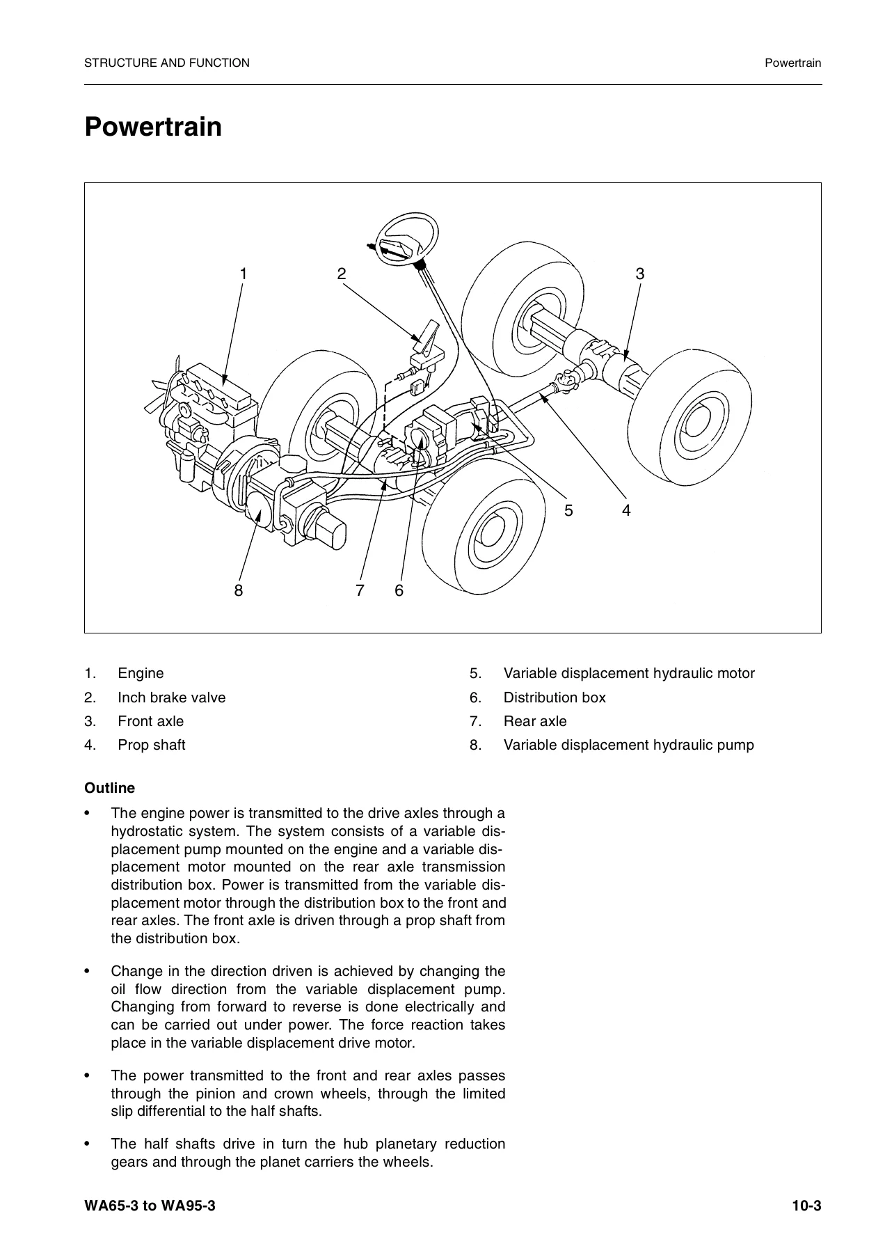
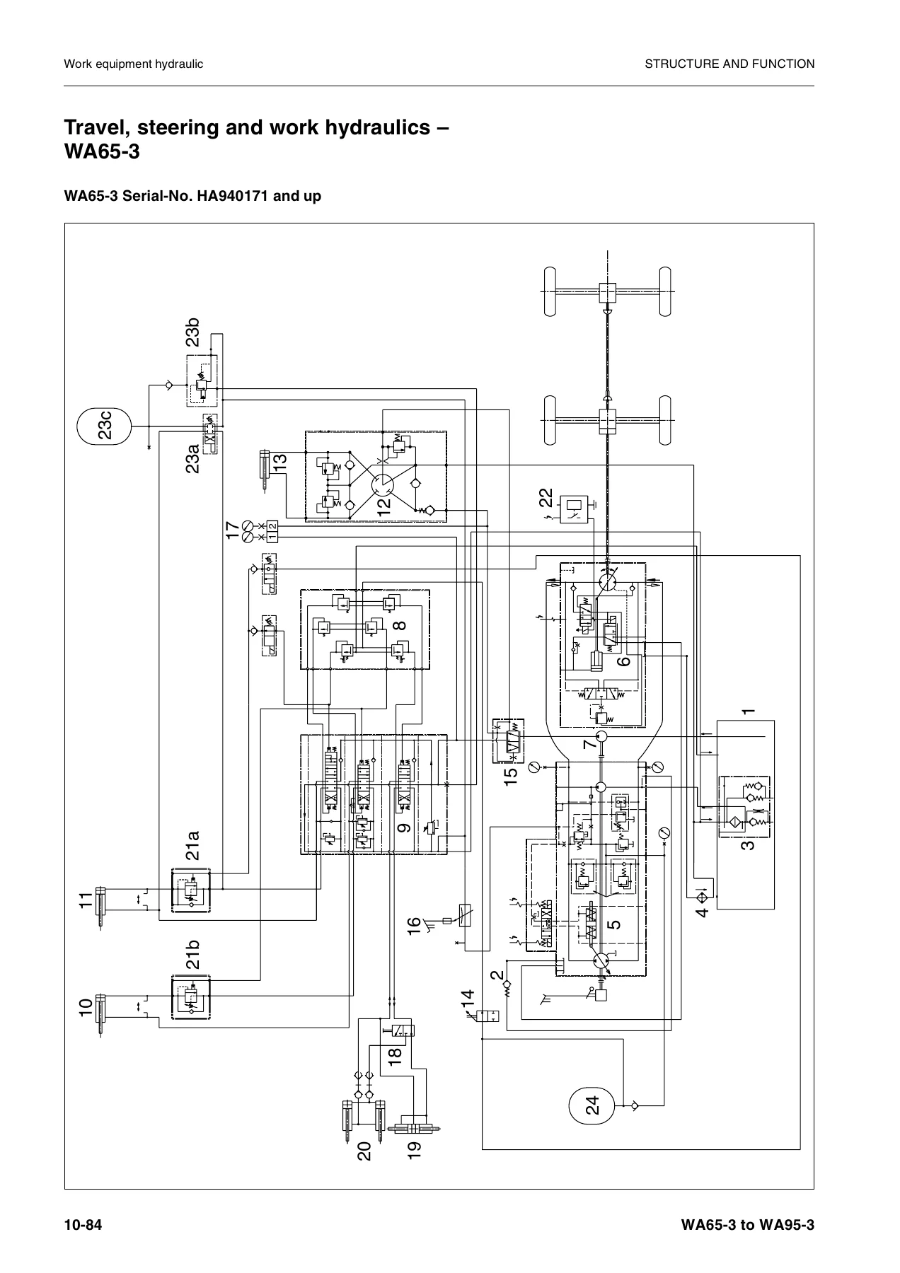
This is the technical heart of the manual. It explains how the hydrostatic drive system works, beginning with the closed circuit and the variable displacement pump. The regulating valve, charge pressure limiting valve, control cylinder, 4/3 way valve with direction control solenoids, pressure cut-off valve and safety/charge valve are all described with cross-section illustrations. Towing procedure and the bypass function are covered, followed by the variable displacement motor and its swash plate control. The drive shaft, axle mounting, front and rear axles, distributor box variants (single stage 20 km/h and double stage 30 km/h) and the limited slip differential are explained. The service and parking brake circuits, the inch-brake valve, the steering articulation joint and the steering system with priority valve and orbit-roll valve are documented. Work equipment hydraulics are covered through the travel, steering and work hydraulic circuit diagrams for each model. Lift, dump and steering cylinders are described with their dimensions, tightening torques and operating pressures. Bucket positioner function and monitor display symbols are also included.
20 Testing and Adjusting
This chapter provides the standard value tables and test certificates that a technician needs to judge machine condition. It covers engine speeds, chassis values and electrical component tests for each model. Specific procedures include valve clearance testing and adjustment, engine compression test, injection nozzle pressure, fuel injection timing, fan belt tension, engine RPM, RPM-dependent drive take-up, engine stall torque RPM, feed pump and servo oil pressure, hydraulic pressure cut-off, working hydraulic pressure, steering oil pressure, steering wheel operating time and force, brake lining and disc wear, brake disc clearance, brake bleeding, inch valve basic adjustment, parking brake setting, brake efficiency, travel speed and the standard value table for electrical parts.
30 Disassembly and Assembly
The largest chapter walks through removal and installation of every major assembly. It starts with the starter, alternator, water pump, engine cover and engine assembly, then moves through the clutch, radiator, fan and pulley, inch brake valve, priority valve, steering valve, counterweight, main control valve and pilot valve. Monitor assembly, articulated joint, variable motor, rear axle and front axle are covered with the special tools and torque values required. The rear axle section for WA65-3/WA75-3/WA85-3 and WA90-3/WA95-3 includes brake disc replacement, wheel hub, planetary gear, bevel pinion support and adjustment of the bevel gear set. The 30 km/h reduction gear, variable displacement pump, hydraulic pump, quick-attach coupler and all three cylinder assemblies (steering, lift and dump) round out the chapter. A section on replacing the cab windows closes it.
90 Appendix
The appendix contains the wiring diagrams for the machine, including Figure 1 through Figure 4 and the later 1a through 5a diagrams introduced from the listed serial numbers onward. These foldout-style diagrams show the electrical circuits, connectors and fuse assignments used throughout the machine.
What This Shop Manual Lets You Do
With this manual on hand, a technician can carry out scheduled maintenance, diagnose hydraulic and electrical faults, adjust pressures and clearances to specification, and rebuild major assemblies — axles, brakes, cylinders, pumps, motors and the hydrostatic drive system. The testing and adjusting chapter gives the numbers needed to decide whether a component is within limits or due for replacement, and the disassembly and assembly chapter gives the order of operations, the special tools and the torque values to put it back together correctly.
Correct procedures and specifications are what separate a repair that lasts from one that comes back. Komatsu builds these wheel loaders to work hard, and the tolerances, pressures and wear limits in this manual are what keep them working. Guessing at a torque value or a brake disc clearance is expensive; having the number in front of you is not.
IMAGES PREVIEW
This Komatsu wheel loader shop manual is delivered as an instant PDF download. There is no shipping, no waiting for a disc, and no restriction on which device you read it on — workshop PC, laptop, tablet or phone. Print the pages you need for the job at hand and keep the rest on file. Whether you are servicing a single WA65-3 or running a fleet that spans the WA65-3 through WA95-3 range, this manual is a working reference you will come back to.

Reviews
There are no reviews yet.