Komatsu WHEEL LOADER WA320 -6 WA320PZ-6 Shop Manual SEN04162-16 PDF
$37.95
Komatsu WHEEL LOADER WA320 -6 WA320PZ-6 Shop Manual SEN04162-16 – PDF DOWNLOAD
SERIAL NUMBERS WA320- 70001
WA320PZ-70001 and up
Description
Komatsu WHEEL LOADER WA320 -6 WA320PZ-6 Shop Manual SEN04162-16 – PDF DOWNLOAD
FILE DETAILS:
Komatsu WHEEL LOADER WA320 -6 WA320PZ-6 Shop Manual SEN04162-16 – PDF DOWNLOAD
Language : English
Pages :1368
Downloadable : Yes
File Type : PDF
IMAGES PREVIEW OF THE MANUAL:
DESCRIPTION:
Komatsu WHEEL LOADER WA320 -6 WA320PZ-6 Shop Manual SEN04162-16 – PDF DOWNLOAD
SERIAL NUMBERS WA320- 70001
WA320PZ-70001 and up
1. General precautions
Mistakes in operation are extremely dangerous. Read the Operation and Maintenance Manual carefully before operating the machine. In addition, read this manual and understand its contents before starting the work.
TABLE OF CONTENTS:
Komatsu WHEEL LOADER WA320 -6 WA320PZ-6 Shop Manual SEN04162-16 – PDF DOWNLOAD
SERIAL NUMBERS WA320- 70001
WA320PZ-70001 and up
COVER 1
00 Index and foreword 3
100 Index 3
Composition of shop manual 4
Table of contents 6
200 Foreword and general information 17
Safety notice 18
How to read the shop manual 23
Explanation of terms for maintenance standard 25
Handling of electric equipment and hydraulic component 27
Handling of connectors newly used for engines 36
How to read electric wire code 39
Precautions when carrying out operation 42
Method of disassembling and connecting push-pull type coupler 45
Standard tightening torque table 48
Conversion table 52
01 Specification 59
100 Specification and technical data 59
Specification dimension drawing 61
Specifications 62
Weight table 66
Table of fuel, coolant and lubricants 68
10 Structure, function and maintenance standard 71
100 Engine and cooling system 71
Engine mount and transfer mount 72
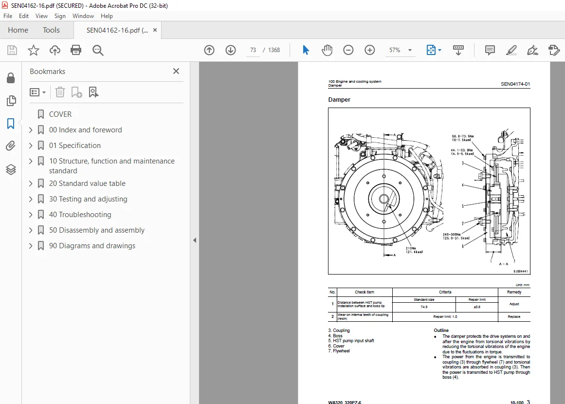
Damper 73
Cooling system 74
Cooling system hydraulic piping diagram 75
Cooling fan motor 77
200 Power train 87
Power train 89
Power train system diagram 90
Drive shaft 92
HST hydraulic piping diagram 93
HST pump 94
HST motor 102
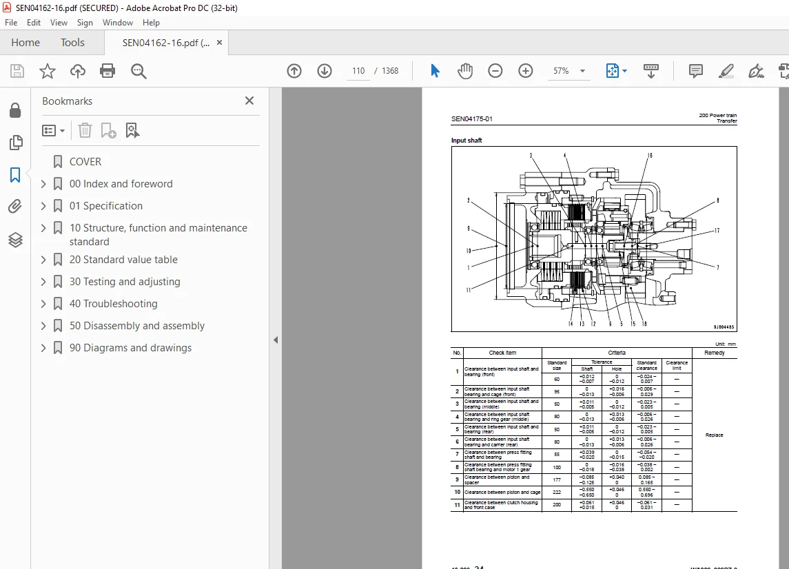
Transfer 108
Clutch solenoid valve 119
Axle 120
Differential 122
Torque proportioning differential 127
Limited slip differential 130
Final drive 134
300 Steering system 139
Steering piping diagram 141
Steering column 142
Priority valve 143
Orbit-roll valve 146
Cushion valve 154
Steering cylinder 155
Emergency steering piping diagram 157
Emergency steering valve 158
Steering relief valve 161
400 Brake system 163
Brake piping diagram 165
Charge valve 166
Brake valve 170
Inching valve 174
Accumulator (for brake) 175
Slack adjuster 176
Brake 178
Parking brake control 183
Parking brake 184
500 Undercarriage and frame 187
Axle mount and center hinge pin 188
Tires 197
600 Hydraulic system 199
Work equipment hydraulic piping diagram 200
Work equipment control lever linkage 204
Hydraulic tank 208
4-gear pump 210
Work equipment control valve 212
Cut-off valve 238
PPC valve 241
Lock valve 256
Accumulator (for PPC circuit) 257
ECSS valve 259
Accumulator (for ECSS) 261
700 Work equipment 263
Work equipment linkage 264
Bucket 268
Bucket positioner and boom kick-out 272
Work equipment cylinder 284
800 Cab and its attachments 287
Cab 289
Air conditioner 290
910 Electrical system, Part 1 303
Machine monitor system 304
Machine monitor 308
Rearview monitor system 329
920 Electrical system, Part 2 335
Electrical system (HST controller system) 336
HST controller 352
ECSS system 354
KOMTRAX system 356
Engine starting circuit 358
Engine stopping circuit 360
Preheating circuit 361
Engine output derating function 362
Automatic warm-up function 362
Parking brake circuit 364
Coupler plunger control system 366
Max traction switch 367
Multi-function knob 368
Sensor 369
20 Standard value table 377
100 Standard service value table 377
Standard service value table for engine 378
Standard service value table for chassis 379
30 Testing and adjusting 387
110 Testing and adjusting, Part 1 387
Tools for testing, adjusting, and troubleshooting 389
Measuring engine speed 394
Measuring exhaust gas color 396
Adjusting valve clearance 398
Measuring compression pressure 400
Measuring blow-by pressure 403
Measuring engine oil pressure 404
Measuring intake air (boost) pressure 405
Handling fuel system equipment 407
Releasing residual pressure in fuel system 407
Measuring fuel pressure 408
Measuring fuel return rate and leakage 410
Bleeding air from fuel circuit 414
Checking leakage in fuel system 415
Handling cylinder cut-out mode operation 416
Handling no-injection cranking operation 416
Handling controller voltage circuit 417
Check of muffler and muffler stack for looseness and damage 417
Check of muffler function 418
Check of installed condition of cylinder head and manifolds 418
Check of engine piping for damage and looseness 419
Checking and replacing alternator belt 420
Checking and replacing auto- tensioner 422
120 Testing and adjusting, Part 2 425
Checking operating force of accelerator pedal 427
Checking directional lever 428
Testing and adjusting HST oil pressure 429
Testing clutch control pressure 433
Testing and adjusting steering wheel 434
Testing and adjusting steering oil pressure 436
Bleeding air from steering circuit 438
Testing hydraulic fan 439
Measuring brake pedal 441
Testing and adjusting brake pedal linkage 442
Measuring brake performance 443
Testing and adjusting accumulator charge pressure 444
Testing wheel brake oil pressure 446
Testing wear of brake disc 449
Bleeding air from wheel brake circuit 450
Releasing residual pressure in brake accumulator circuit 451
Testing parking brake performance 452
Testing and adjusting parking brake control cable 453
Measuring and adjusting work equipment control lever 454
Testing and adjusting work equipment hydraulic pressure 455
Testing work equipment PPC oil pressure 456
Bleeding air from hydraulic circuit 458
Releasing remaining pressure in hydraulic circuit 459
Testing and adjusting bucket positioner 460
Testing and adjusting of boom kick-out switch 461
Checking proximity switch operation pilot lamp 462
Procedure for testing diodes 463
Preparation work for troubleshooting for electric system 464
Starting KOMTRAX terminal operations 468
Indicator lamps of KOMTRAX terminal 472
Adjustment of rearview camera angle 475
130 Testing and adjusting, Part 3 477
Adjusting machine monitor 478
Adjusting replaced, reassembled or added sensor, controller, etc with machine monitor 479
Special functions of machine monitor (EMMS) 481
Pm clinic inspection chart 534
40 Troubleshooting 537
100 Failure code table and fuse locations 537
Failure codes table 538
Fuse locations 544
200 General information on troubleshooting 549
Points to remember when troubleshooting 550
Sequence of events in troubleshooting 551
Testing before troubleshooting 552
Classification and procedures of troubleshooting 553
Information contained in troubleshooting table 556
Connection table for connector pin numbers 558
T- branch box and T- branch adapter table 594
310 Troubleshooting by failure code (Display of code), Part 1 599
Failure code [2G40ZG] Brake: Oil pressure reduction 600
Failure code [6091NX] HST filter: Clogging 602
Failure code [989FN1] Travel speed: Overrun alarm 603
Failure code [AA1ANX] Air cleaner: Clogging 604
Failure code [AB00L6] Alternator R system: Hot short 606
Failure code [AB00MA] Alternator R system: Ground fault/Disconnection/Low charge voltage 608
Failure code [B@BAZG] Engine: Oil pressure reduction 610
Failure code [B@BAZK] Engine oil: Low level 611
Failure code [B@BCNS] Engine: Overheat 612
Failure code [B@BCZK] Engine: Low coolant level 614
Failure code [B@C6NS] Front brake: High oil temperature 616
Failure code [B@CRNS] HST: High oil temperature 617
320 Troubleshooting by failure code (Display of code), Part 2 619
Failure code [CA111] Abnormality in engine controller 621
Failure code [CA115] Engine Ne or Bkup speed sensor error 622
Failure code [CA122] Charge pressure sensor high error 624
Failure code [CA123] Charge pressure sensor low error 626
Failure code [CA131] Throttle sensor high error 628
Failure code [CA132] Throttle sensor low error 630
Failure code [CA144] Coolant sensor high error 632
Failure code [CA145] Coolant sensor low error 634
Failure code [CA153] Charge temperature sensor high error 636
Failure code [CA154] Charge temperature sensor low error 638
Failure code [CA155] Derating of speed by abnormally high charge temperature 640
Failure code [CA187] Sensor power supply 2 low error 642
Failure code [CA221] Atmospheric pressure sensor high error 644
Failure code [CA222] Atmospheric sensor low error 646
Failure code [CA227] Sensor power supply 2 high error 648
Failure code [CA234] Engine overspeed 649
Failure code [CA238] Ne speed sensor power supply error 650
Failure code [CA271] IMV (IMA) Short circuit 651
Failure code [CA272] IMV (IMA) Disconnection 652
Failure code [CA322] Injector #1 open/short error 654
Failure code [CA323] Injector #5 open/short error 656
Failure code [CA324] Injector #3 open/short error 658
Failure code [CA325] Injector #6 open/short error 660
Failure code [CA331] Injector #2 open/short error 662
Failure code [CA332] Injector #4 open/short error 664
Failure code [CA342] Calibration code inconsistency 666
Failure code [CA351] Injectors drive circuit error 668
Failure code [CA352] Sensor power supply 1 low error 670
Failure code [CA386] Sensor power supply 1 high error 672
330 Troubleshooting by failure code (Display of code), Part 3 675
Failure code [CA428] Abnormally high level in water sensor 678
Failure code [CA429] Abnormally low level in water sensor 680
Failure code [CA431] Idle validation switch error 682
Failure code [CA432] Idle validation action error 686
Failure code [CA435] Engine oil pressure switch error 690
Failure code [CA441] Battery voltage low error 691
Failure code [CA442] Battery voltage high error 694
Failure code [CA449] Common rail pressure high error 2 696
Failure code [CA451] Common rail pressure sensor high error 698
Failure code [CA452] Common rail pressure sensor low error 700
Failure code [CA488] Derating of torque by abnormally high charge temperature 702
Failure code [CA553] Common rail pressure high error 1 703
Failure code [CA559] Supply pump pressure very low error 704
Failure code [CA689] Engine Ne speed sensor error 706
Failure code [CA731] Engine Bkup speed sensor phase error 708
Failure code [CA757] All continuous data lost error 709
Failure code [CA778] Engine Bkup speed sensor error 712
Failure code [CA1633] KOMNET datalink timeout error 714
Failure code [CA2185] Throttle sensor supply voltage high error 718
Failure code [CA2186] Throttle sensor power supply low error 720
Failure code [CA2249] Supply pump pressure very low error 2 722
Failure code [CA2311] Abnormality in IMV (IMA) solenoid 724
Failure code [CA2555] Intake heater relay disconnection error 726
Failure code [CA2556] Intake heater relay short circuit error 728
340 Troubleshooting by failure code (Display of code), Part 4 731
Failure code [D160KY] Backup alarm/lamp relay 1 circuit: Hot short 732
Failure code [D192KY] ECSS solenoid relay: Hot short 734
Failure code [D1B0KA] HST safety relay: Disconnection 736
Failure code [D1B0KB] HST safety relay: Ground fault 738
Failure code [D1B0KY] HST safety relay: Hot short 740
Failure code [D5ZHL6] IGN C system: Ground fault/Disconnection 742
Failure code [DAF3KK] UNSW power supply: Ground fault/Disconnection 744
Failure code [DAFRKR] Machine monitor CAN-NET Signal: Disconnection 746
Failure code [DAJ0KK] HST controller power supply: Low voltage 750
Failure code [DAJ0KT] HST controller memory (EEPROM): Abnormality 752
Failure code [DAJ1L4] HST controller main power line: Disconnection/Ground fault 754
Failure code [DAJ1L6] HST controller main power line: Hot short 756
Failure code [DAJ2KK] Controller solenoid power supply: Low voltage 758
Failure code [DAJ2L3] HST controller load power supply holding line: Hot short in wiring harness 760
Failure code [DAJ2L4] HST controller load power supply holding line: Disconnection/Ground fault 762
Failure code [DAJ5KX] Sensor 5V power supply: Out of output range 764
Failure code [DAJ9KQ] HST controller model selection: Disagreement of model selection signals 766
Failure code [DAJRKR] HST controller CAN-NET signal: Disconnection 767
Failure code [DAJRMA] HST controller: Disagreement in option selection 773
350 Troubleshooting by failure code (Display of code), Part 5 775
Failure code [DB2RKR] Engine controller CAN-NET: Disconnection in signal line 776
Failure code [DD1NL4] Fan automatic reverse switch signal: Abnormality 782
Failure code [DD1NLD] Fan reverse switch signal: Abnormality 784
Failure code [DDB6KA] Parking brake reminder signal: Disconnection/Hot short 786
Failure code [DDB6KB] Parking brake indicator signal: Ground fault 788
Failure code [DDB6KZ] Parking brake switch (bottom switch) or parking brake reminder switch (intermediate switch): Trouble 790
Failure code [DDB6L0] Parking brake reminder signal: Ground fault 792
Failure code [DDB6L4] Parking brake indicator signal: Disconnection/Hot short 794
Failure code [DDD7KX] Travel speed control dial signal: Disconnection/Ground fault 796
Failure code [DDD7KY] Travel speed control dial signal: Hot short 798
Failure code [DDE5MA] Emergency steering operation switch: Disconnection 800
Failure code [DDK6KA] FNR lever: Disconnection/Ground fault 802
Failure code [DDK6KY] FNR lever: Hot short 806
Failure code [DDS5L6] Steering: Low oil pressure (Operation of emergency steering) 808
360 Troubleshooting by failure code (Display of code), Part 6 811
Failure code [DF10KA] Travel speed range selector switch: Disconnection/Ground fault 812
Failure code [DF10KB] Travel speed range selector switch: Hot short 816
Failure code [DGH1KX] HST oil temperature sensor: Ground fault 818
Failure code [DGR2KB] Brake oil temperature sensor: Ground fault 819
Failure code [DGR2KZ] Brake oil temperature sensor: Disconnection/Hot short 820
Failure code [DHH1KX] HST oil pressure sensor: Disconnection/Ground fault 822
Failure code [DHH1KY] HST oil pressure sensor: Hot short 824
Failure code [DHTCL6] HST filter clogging sensor: Functional defect 826
Failure code [DJF1KA] Fuel level sensor: Disconnection/Hot short 828
Failure code [DLT3KX] Travel speed sensor B: Abnormality 830
Failure code [DLT4KX] Travel speed sensor A: Abnormality 834
Failure code [DLT4LC] Travel speed sensor A & B: Abnormality 836
Failure code [DV00KY] Alarm buzzer: Hot short 838
Failure code [DW26KA] Motor 2 solenoid: Disconnection/Ground fault 840
Failure code [DW26KY] Motor 2 solenoid: Hot short 842
Failure code [DW7BKY] Fan reverse solenoid circuit: Hot short 844
Failure code [DW7BKZ] Fan reverse solenoid circuit: Disconnection/Ground fault 846
370 Troubleshooting by failure code (Display of code), Part 7 849
Failure code [DX16KA] Fan EPC solenoid: Disconnection 850
Failure code [DX16KB] Fan EPC solenoid: Ground fault 851
Failure code [DX16KY] Fan EPC solenoid: Hot short 852
Failure code [DX19KA] Motor 1 solenoid: Disconnection 854
Failure code [DX19KB] Motor 1 solenoid: Ground fault 856
Failure code [DX19KY] Motor 1 solenoid: Hot short 858
Failure code [DX20KA] Clutch EPC solenoid: Disconnection 860
Failure code [DX20KB] Clutch EPC solenoid: Ground fault 862
Failure code [DX20KY] Clutch EPC solenoid: Hot short 864
Failure code [DXH7KB] Reverse solenoid: Ground fault 866
Failure code [DXH7KZ] Reverse solenoid: Disconnection/Hot short 868
Failure code [DXH8KB] Forward solenoid: Ground fault 870
Failure code [DXH8KZ] Forward solenoid: Disconnection/Hot short 872
Failure code [J141N1] Steering pump: Overrun alarm 874
Failure code [M100N1] HST pump: Overrun alarm 874
Failure code [M400N1] Motor 1: Overrun alarm 875
400 Troubleshooting of electrical system (E-mode) 877
E-1 Engine does not start 879
E-2 Preheater does not operate normally 886
E-3 Travel speed is low or high 890
E-4 ECSS does not operate 896
E-5 ECSS keeps operating 899
E-6 Defective boom kick-out function and cancellation 902
E-7 Defective bucket positioner function and cancellation 906
E-8 Defective lift arm FLOATING holding function and cancellation 910
E-9 Travel direction selection system does not function 914
E-10 Fan does not reverse 918
E-11 Fan keeps rotating in reverse 922
E-12 Wiper does not operate 924
E-13 Windshield washer does not operate 928
E-14 Headlamp, clearance lamp and tail lamp do not light up or go off 932
E-15 Working lamp does not light up or go off 940
E-16 Turn signal lamp and hazard lamp do not light up or go off 946
E-17 Brake lamp does not light or it keeps lighting up 952
E-18 Backup lamp does not light or it keeps lighting up 954
E-19 Backup alarm does not sound or it keeps sounding 957
E-20 Horn does not sound or it keeps sounding 960
E-21 Alarm buzzer does not sound or it keeps sounding 962
E-22 Air conditioner does not operate or stop 964
E-23 The KOMTRAX system does not work properly 968
E-24 Rearview monitor does not light up or backlight flickers 970
E-25 Rearview monitor images are not displayed clearly 974
E-26 Rearview monitor brightness cannot be adjusted 978
E-27 Night lighting lamp of rearview monitor is abnormal 982
E-28 Reverse interlock function of rearview monitor does not operate properly 985
500 Troubleshooting of hydraulic and mechanical system (H-mode) 989
Method of using troubleshooting chart 991
Failure code and cause table 994
H-1 The machine does not start 996
H-2 The travel speed is slow 997
H-3 The traction force is weak 998
H-4 Engine stalls when traveling or engine speed drops excessively 999
H-5 Shift range is not shifted1000
H-6 The steering wheel does not turn1001
H-7 The steering wheel is heavy1002
H-8 Steering wheel shakes or jerks1003
H-9 Machine deviates naturally to one side when traveling1003
H-10 The brake does not work or does not work well1004
H-11 The brake is not released or is dragged1005
H-12 The lift arm does not rise or lower1006
H-13 The lift arm moves slowly or the lift arm rising force is insufficient1007
H-14 When rising, the lift arm comes to move slowly at specific height1008
H-15 The lift arm cylinder cannot hold down the bucket (The bucket rises in the air)1008
H-16 Hydraulic drifts of the lift arm occur often1008
H-17 The lift arm wobbles during operation1008
H-18 When the control lever is switched from “HOLD” to “RAISE,” the lift arm falls temporarily1009
H-19 The bucket does not tilt back1010
H-20 The bucket moves slowly or the tilting-back force is insufficient1011
H-21 The bucket comes to operate slowly in the midst of tilting-back1012
H-22 The bucket cylinder cannot hold down the bucket1012
H-23 Hydraulic drifts of the bucket occur often1012
H-24 The bucket wobbles during travel with load (The work equipment valve is set to “HOLD”)1012
H-25 When the control lever is switched from “HOLD” to “TILT,” the bucket falls temporarily1013
H-26 The control levers of the lift arm and bucket do not move smoothly and heavy1013
H-27 The ECSS does not operate and machine pitches and bounces1014
H-28 Fan revolution is abnormal (Fan sound/vibration is abnormally large or engine overheats)1015
600 Troubleshooting of engine (S-mode)1017
Method of using troubleshooting charts1018
S-1 Starting performance is poor1022
S-2 Engine does not start1024
S-3 Engine does not pick up smoothly1027
S-4 Engine stops during operations1028
S-5 Engine does not rotate smoothly1029
S-6 Engine lacks output (or lacks power)1030
S-7 Exhaust smoke is black (incomplete combustion)1031
S-8 Oil consumption is excessive (or exhaust smoke is blue)1032
S-9 Oil becomes contaminated quickly1033
S-10 Fuel consumption is excessive1034
S-11 Oil is in coolant (or coolant spurts back or coolant level goes down)1035
S-12 Oil pressure drops1036
S-13 Oil level rises (Entry of coolant or fuel)1037
S-14 Coolant temperature becomes too high (overheating)1038
S-15 Abnormal noise is made1039
S-16 Vibration is excessive1040
50 Disassembly and assembly1043
100 General information on disassembly and assembly1043
How to read this manual1044
Coating materials list1046
Special tool list1049
Sketches of special tools1053
200 Engine and cooling system1061
Removal and installation of fuel supply pump assembly1062
Removal and installation of fuel injector assembly1066
Removal and installation of cylinder head assembly1075
Removal and installation of engine hood assembly1088
Removal and installation of radiator1091
Removal and installation of air aftercooler1094
Removal and installation of hydraulic oil cooler assembly1096
Removal and installation of engine assembly1098
Removal and installation of engine front oil seal assembly1104
Removal and installation of engine rear oil seal assembly1107
Removal and installation of cooling fan and fan motor assembly1110
Removal and installation of fuel tank assembly1113
310 Power train, Part 11117
Removal and installation of transfer assembly1118
Disassembly and assembly of transfer assembly1122
Removal and installation of parking brake assembly1142
Disassembly and assembly of parking brake assembly1143
320 Power train, Part 21149
Removal and installation of front axle assembly1150
Removal and installation of rear axle assembly1152
Disassembly and assembly of axle housing assembly1155
Disassembly and assembly of differential assembly1167
400 Undercarriage and frame1191
Removal and installation of center hinge pin1192
Removal and installation of counterweight assembly1204
500 Hydraulic system1207
Removal and installation of HST pump and 4-gear pump assembly1208
Disassembly and assembly of HST pump assembly1211
Removal and installation of HST motor 1 assembly1238
Removal and installation of HST motor 2 assembly1240
Disassembly and assembly of HST motor assembly1242
Removal and installation of work equipment control valve assembly1258
Removal and installation of hydraulic tank assembly1260
Disassembly and assembly of hydraulic cylinder assembly1262
600 Work equipment1271
Removal and installation of work equipment assembly1272
700 Cab and its attachments1279
Removal and installation of operator’s cab and floor frame assembly1280
Removal and installation of operator’s cab glass (Stuck glass)1286
Disassembly and assembly of operator’s seat assembly1294
Removal and installation of air conditioner unit1304
800 Electrical system1309
Removal and installation of monitor panel1310
Removal and installation of engine controller assembly1312
Removal and installation of HST controller assembly1313
Removal and installation of KOMTRAX terminal assembly1314
90 Diagrams and drawings1317
100 Hydraulic diagrams and drawings1317
Automatic greasing circuit diagram1318
Hydraulic circuit diagram1321
200 Electrical diagrams and drawings1327
Common electrical circuit diagram1329
Connector list and stereogram1365
S.M 29/12/24