Komatsu Wheel Loader WA470-3 Shop Manual VEBM480104 – PDF DOWNLOAD
$36.95
Komatsu Wheel Loader WA470-3 Shop Manual VEBM480104 – PDF DOWNLOAD
Serial Number
WA470H20051 and up
Description
Komatsu Wheel Loader WA470-3 Shop Manual VEBM480104 – PDF DOWNLOAD
FILE DETAILS:
Komatsu Wheel Loader WA470-3 Shop Manual VEBM480104 – PDF DOWNLOAD
Language : English
Pages :1006
Downloadable : Yes
File Type : PDF
DESCRIPTION:
Komatsu Wheel Loader WA470-3 Shop Manual VEBM480104 – PDF DOWNLOAD
Serial Number
WA470H20051 and up
FOREWORD GENERAL
- This shop manual has been prepared as an aid to improve the quality of repairs by giving the service personnel an accurate understanding of the product and by showing them the correct way to perform repairs and make judgements. Make sure you understand the contents of this manual and use it to full effect at every opportunity.
- This shop manual mainly contains the necessary technical information for operations performed in a service workshop. For ease of understanding, the manual is divided into the following chapters; these chapters are further divided into the each main group of components
STRUCTURE AND FUNCTION
This section explains the structure and function of each component. It serves not only to give an
understanding of the structure, but also serves as reference material for troubleshooting.
TESTING AND ADJUSTING
This section explains checks to be made before and after performing repairs, as well as adjustments
to be made at completion of the checks and repairs.
Troubleshooting charts correlating “Problems” to “Causes” are also included in this section.
DISASSEMBLY AND ASSEMBLY
This section explains the order to be followed when removing, installing, disassembling or assembling
each component, as well as precautions to be taken for these operations.
MAINTENANCE STANDARD
This section gives the judgement standards when inspecting disassembled parts
TABLE OF CONTENTS:
Komatsu Wheel Loader WA470-3 Shop Manual VEBM480104 – PDF DOWNLOAD
Serial Number
WA470H20051 and up
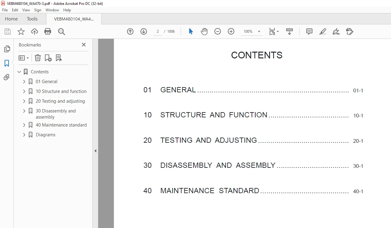
Contents 2
01 General 9
Up to SN WA470H20668 11
Dimensions and weights 11
Specifications 12
Weight table 14
List of lubricant and water 15
From SN WA470H20669 up to SN WA470H20941 16
Dimensions and weights 16
Specifications 17
Weight table 19
List of lubricant and water 20
SN WA470H20942 and up 21
Specifications 21
Weight table 22
List of lubricant and water 23
Outlines of service 25
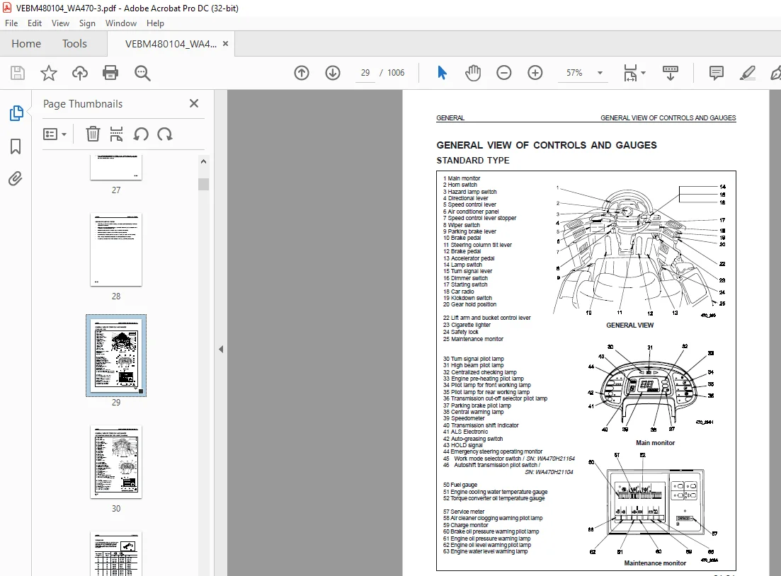
General view of controls and gauges 29
Torque list 31
10 Structure and function 33
Power train 35
Power train system 36
Torque converter, transmission piping 38
Transmission hydraulic system diagram 39
Transmission hydraulic circuit diagram 40
Torque converter 41
Transmission 45
Clutch 47
Transmission control valve 55
Transmission solenoid valve 58
Main relief valve 60
Torque converter outlet port valve 61
Priority valve 62
Directional selector valve 66
H-L selector valve and range selector valve 67
Emergency manual spool 69
Electronic control modulation valve (ECMV) 70
Pilot oil filter 73
Accumulator valve 74
Flow valve 76
Drive shaft 79
Axle 80
Differential 82
Final drive 89
Axle mount, center hinge pin 90
Steering piping 91
Steering column, orbit roll 92
Orbit-roll valve 94
Steering demand valve 95
Overload relief valve 96
Steering relief valve 98
Operation of demand valve 99
Emergency steering 109
Brake piping 119
Brake circuit diagram 120
Brake valve 121
Charge valve 126
Accumulator for system brake 130
Slack adjuster 131
Brake pressure regulating valve 142
Accumulator for PPC valve 144
Brake accumulator unit 146
Brake 147
Parking brake control 149
Parking brake 150
Parking brake valve 151
Hydraulic piping 153
Work equipment hydraulic system diagram 154
Work equipment hydraulic circuit diagram 156
Work equipment lever linkage 162
Hydraulic tank 163
Breather 164
PPC valve 165
PPC relief valve 173
Accumulator for PPC valve 174
Cut-off valve 175
Main control valve 177
Relief valve 185
Safety valve (with suction) 186
Suction valve 187
Hydraulic safety system 197
Work equipment linkage 201
Bucket 203
Bucket positioner and boom kick-out 204
Machine monitor system 211
Transmission auto-shift control system 219
Transmission controller 224
ECSS (electronic controlled suspension system) 227
ALS system 231
Sensors 237
Engine start circuit 243
Engine stop circuit 244
Preheating circuit 245
Ribbon heater 250
Electric transmission control 251
Combination switch 252
Kick-down, hold switch 254
Transmission electric circuit diagram 255
Transmission cut-off switch 260
Transmission cut-off function 261
Electric parking brake control 262
Air-conditioner 263
Wiring diagrams 317
20 Testing and adjusting 353
Standard value table for engine 354
Standard value table for chassis 357
Test certificate 360
Standard value table for electrical parts 365
Tools for testing, adjusting and troubleshooting 369
Frm SN WA470H20669 up to SN WA470H20941: MTA11(STC) 374
Measuring engine speed 375
Measuring intake air pressure 376
Testing and adjusting valves and injectors 377
Measuring blow-by pressure 384
Measuring engine oil pressure 385
Testing the fan belt tension 386
Measuring stall speed 388
Up to SN WA470H20668: S6D125-1; SN WA470H20942 and up:SA6D125E-2 391
Measuring engine speed 391
Measuring intake air pressure (boost pressure) 392
Adjusting valve clearance 393
Mesuring exhaust color 394
Measuring exhaust gas temperature 395
Measuring blow-by pressure 396
Measuring compression pressure 397
Measuring engine oil pressure 398
Testing and adjusting fuel injection timing 399
Method for adjusting engine motor stop cable 401
Testing and adjusting fan belt tension 403
Measuring accelerator pedal 404
Basic adjustment of accelerator pedal 406
Measuring operating force, travel of speed lever 408
Measuring stall speed 409
Measuring torque converter, transmission, parking brake oil pressure 411
Method of operating emergency manual spool 413
Measuring clearance between tyre and wheel 415
Measuring steering oil pressure 418
Measuring brake performance 421
Testing brake oil pressure 422
Measuring brake disc wear 423
Bleeding air from brake system 424
Measuring parking brake performance 425
Method of manual release of parking brake 426
Testing wear of parking brake disc 427
Measuring work equipment control lever 428
Measuring work equipment hydraulic pressure 430
Measuring PPC valve pressure 434
Measuring work equipment 436
Testing and adjusting bucket positioner 438
Testing and adjusting boom kick-out 439
Adjusting main monitor (speedometer modul) 441
Checking for abnormality in fuel level sensor 442
30 Disassembly and assembly 661
Method of using manual 663
Precautions when carrying out operation 664
Special tool list 666
Starting motor 669
Alternator 670
Engine oil cooler 671
Fuel injection pump 672
Water pump 676
Turbocharger 677
Nozzle holder 678
Thermostat 679
Cylinder head 680
Radiator 686
Engine 689
Torque converter charging pump 696
Torque converter, transmission 697
Torque converter 706
Tranmission 711
Transmission clutch pack 722
Parking brake 743
Transmission control valve 748
Transmission accumulator valve 766
Drive shaft 769
Front axle 773
Rear axle 776
Front differential 781
Rear differential 786
Differential 791
Final drive 802
Center hinge pin 809
Steering, orbit roll 823
Steering valve 825
Steering, switch pump 840
Steering cylinder 844
Brake valve 846
Right brake valve (tandem) 848
Left brake valve (single) 850
Slack adjuster 852
Brake 856
Parking brake disc 870
Hydraulic tank 873
Work equipment, PPC pump 876
PPC valve 883
Main control valve 885
Bucket cylinder 893
Boom cylinder 895
Hydraulic cylinder 897
Work equipment 903
Counterweight 908
Fuel tank 909
Cab 911
Main monitor 913
Maintenance monitor 915
Air conditioner unit 916
Air conditioner condenser 922
Dry receiver 924
Air conditioner compressor 925
Tyres 927
40 Maintenance standard 935
Engine mount, transmission mount 936
Torque converter 937
Transmission 938
Transmission control valve 948
Drive shaft 952
Diffential 954
Final drive 956
Axle mount 957
Steerig column, orbit roll 958
Steering valve 960
Steering cylinder mount 961
Slack adjuster 962
Brake valve 963
Brake 966
Parking brake 968
Torque converter, transmission pump 969
Steering, switch pump 970
Hydraulic, PPC pump 971
PPC valve 972
Cut-off valve 973
Main control valve 974
Boom cylinder 978
Bucket cylinder 979
Center hinge pin 980
Work equipment linkage 982
Bucket 984
Bucket positioner and boom kick-out 985
Diagrams 987
Diagrams_A3 987
Diagrams_A21003
IMAGES PREVIEW OF THE MANUAL:
S.M 26/12/24