Komatsu WHEEL LOADER WA500-8 Shop Manual SEN06581-17 – PDF
$40.95
Komatsu WHEEL LOADER WA500-8 Shop Manual SEN06581-17 – PDF DOWNLOAD
SERIAL NUMBERS 90001 and up
Description
Komatsu WHEEL LOADER WA500-8 Shop Manual SEN06581-17 – PDF DOWNLOAD
FILE DETAILS:
Komatsu WHEEL LOADER WA500-8 Shop Manual SEN06581-17 – PDF DOWNLOAD
Language : English
Pages :4276
Downloadable : Yes
File Type : PDF
IMAGES PREVIEW OF THE MANUAL:
DESCRIPTION:
Komatsu WHEEL LOADER WA500-8 Shop Manual SEN06581-17 – PDF DOWNLOAD
SERIAL NUMBERS 90001 and up
How to Read the Shop Manual
• Some of the attachments and options described in this shop manual may not be available in some areas. If
they are required, consult your Komatsu distributor.
• The materials and specifications are subject to change without notice.
• Shop Manuals are available for “machine part” and “engine part”. For the engine unit, see the shop manual
for the machine which has the same engine model.
• Actual machine may differ from the images which are contained in this manual. A typical model is shown in
the illustrations of this shop manual.
• The caution lamps, pilot lamps, and symbols of the switches on the machine monitor can be different in
accordance with the machine.
• For details of the symbols shown on the machine monitor, see Structure and Operation, “Caution
Lamps Shown on Machine Monitor” and “Pilot Lamps Shown on Machine Monitor”.
• For details of the switches of the machine monitor, see Testing and Adjusting, “Set and Operate Machine
Monitor”.
• For details of the switches, see the “Operation and Maintenance Manual”.
• All “AdBlue/DEF” shown on the machine monitor is referred to as “DEF” in the shop manual. Some machine
monitors installed to the product show “DEF” as “AdBlue/DEF” in the service mode. Thus, be sure to recognize
that “DEF” and “AdBlue/DEF” are the same when you read the shop manual.
REMARK
The illustrations in the shop manual reproduce the display of the machine monitor. They are not always the
same as the terminology in the shop manual.
Composition of the Shop Manual
This shop manual contains technical information necessary to perform services in workshops. It is divided into
the following chapters for the ease of use.
00 Index and Foreword
This section describes the index, foreword, safety, and basic information.
01 Specification
This section describes the specifications of the machine.
10 Structure and Function
This section describes the structure and operation of each component with respect to each system. “Structure
and Function” is helpful in not only understanding the structure of each component but performing troubleshooting.
20 Standard Value Table
This section describes the standard values for new machine and failure criteria for testing and adjusting, and
troubleshooting. Use the standard values table to check the standard values for testing and adjusting, and judge
troubles in troubleshooting.
30 Testing and Adjusting
This section describes the measuring tools and measuring methods for testing and adjusting as well as the adjusting
method of each part. The standard values and repair limit for TESTING AND ADJUSTING are described
in “Standard Value Table”.
40 Troubleshooting
This section describes troubleshooting of failure part and its remedy method on the occurrence of the failure.
Descriptions of troubleshooting are sorted by failure mode.
This section describes the special tools, work procedures, and safety precautions necessary for removal, installation,
disassembly, and assembly of the components and parts. In addition, tightening torques, quantity, and
weight of the coating materials, lubricants, and coolant necessary to these works are shown.
60 Maintenance Standard
This section describes the maintenance standard value of each component. The maintenance standard shows
the criteria and remedies for disassembly and assembly.
80 Others
This section describes the structure and function, testing and adjusting, and troubleshooting for all of the other
components or equipment which cannot be separately classified in the appendix.
90 Circuit Diagrams
This section describes hydraulic circuit diagrams and electrical circuit diagrams.
TABLE OF CONTENTS:
Komatsu WHEEL LOADER WA500-8 Shop Manual SEN06581-17 – PDF DOWNLOAD
SERIAL NUMBERS 90001 and up
Cover 1
00 Index and Foreword 3
Index 4
Abbreviation List 30
Foreword, Safety, Basic Information 36
How to Read the Shop Manual 36
Safety Notice for Operation 38
Precautions to Prevent Fire 46
Procedures If Fire Occurs 48
Precautions for Disposing of Waste Materials 49
Procedures for Exhaust Gas Regulations 50
Precautions for DEF 51
General Character and Precautions for Handling 51
Precautions for Adding 51
Precautions for Storage 51
Precautions for Fire Hazard and Leakage 51
Other Precautions 51
Store DEF 52
Precautions When You Handle Hydraulic Equipment 53
Precautions When You Disconnect and Connect Pipings 56
Precautions When You Handle Electrical Equipment 63
Precautions When You Handle Fuel System Equipment 65
Precautions When You Handle Intake System Equipment 66
Practical Use of KOMTRAX 67
Disconnect and Connect Push-Pull Type Coupler 68
How to Disconnect and Connect Type 1 Push-Pull Type Coupler 68
How to Disconnect and Connect Type 2 Push-Pull Type Coupler 69
How to Disconnect and Connect Type 3 Push-Pull Type Coupler 70
Precautions for Disconnection and Connection of Connectors 72
How to Disconnect and Connect Deutsch Connector 76
How to Disconnect and Connect Slide Lock Type Connector 77
How to Disconnect and Connect Connector with Lock to Pull 79
How to Disconnect and Connect Connector with Lock to Push 80
How to Disconnect and Connect Connector with Housing to Rotate 82
How to Read the Codes for Electric Cable 83
Explanation of Terms for Maintenance Standard 87
Standard Tightening Torque Table 90
Conversion Table 97
01 Specifications 103
Table of Contents 104
Abbreviation List 105
Specifications 111
Specification Drawing 111
Specification Drawing: WA500-8 111
Specifications 113
Specifications: WA500-8 113
Weight Table 118
Weight Table: WA500-8 118
Table of Fuel, Coolant, and Lubricants 120
10 Structure and Function 123
Table of Contents 124
Abbreviation List 129
Urea SCR System 135
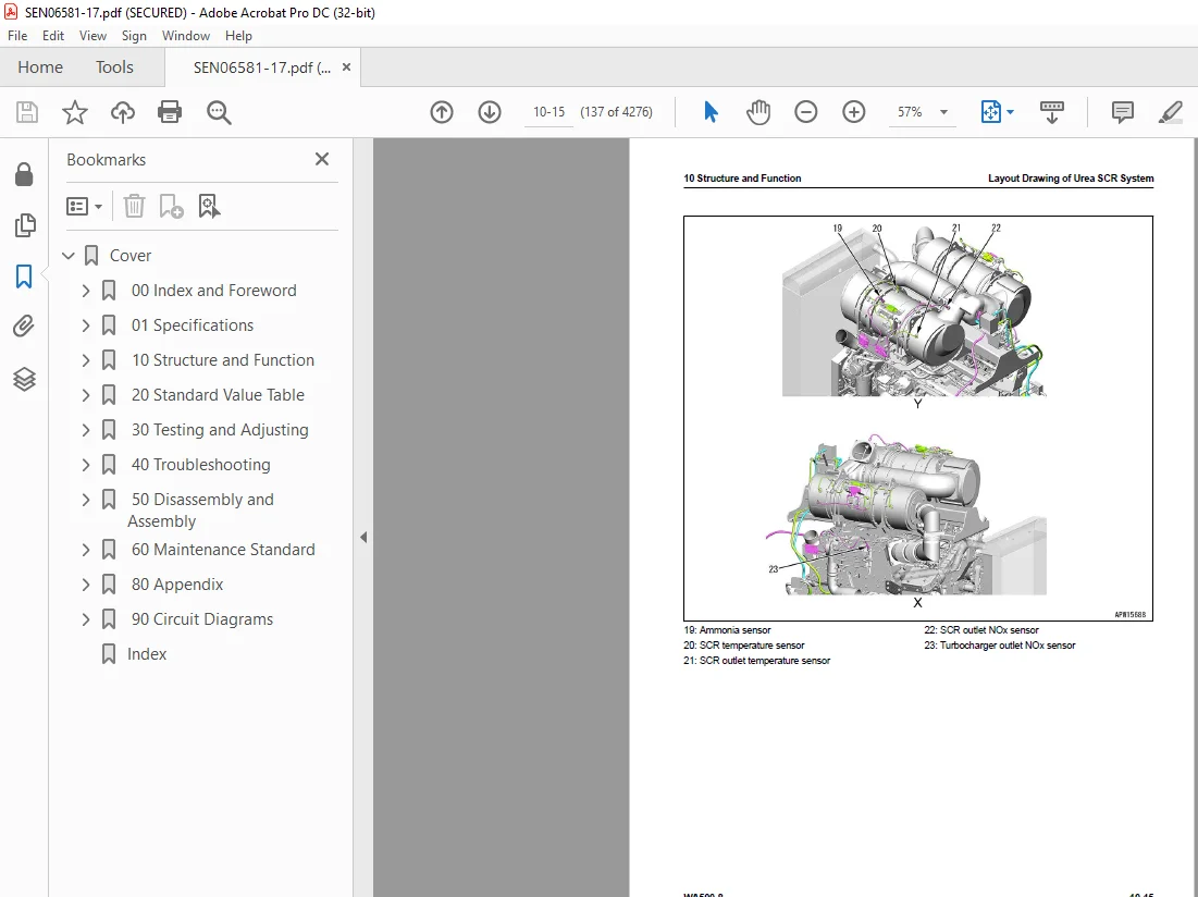
Layout Drawing of Urea SCR System 135
Urea SCR System Diagram 138
Function of Urea SCR System 139
Function of DEF System (Machine Without DEF purge relay) 139
Function of DEF System (Machine with DEF purge relay) 141
Inducement Strategy 144
Component Parts of Urea SCR System 158
DEF Mixing Tube 158
SCR Assembly 159
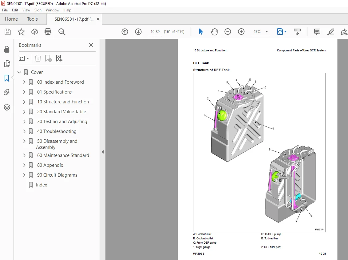
DEF Tank 161
DEF Pump 163
DEF Injector 164
DEF Hose 165
DEF Tank Heating Valve 166
Boot-up System 167
Layout Drawing of Boot-up System (Machine with KOMTRAX Terminal) 167
Layout Drawing of Boot-up System (Machine with Gateway Function Controller) 169
Layout Drawing of Boot-up System (For Emergency Engine Stop Switch Spec) (Machine with KOMTRAX Terminal) 171
Layout Drawing of Boot-up System (For Emergency Engine Stop Switch Spec) (Machine with Gateway Function Controller) 173
System Operating Lamp System 175
System Diagram of System Operating Lamp System (Machine with KOMTRAX Terminal) 175
System Diagram of System Operating Lamp System (Machine with Gateway Function Controller) 175
Function of System Operating Lamp System (Machine with KOMTRAX Terminal) 175
Function of System Operating Lamp System (Machine with Gateway Function Controller) (Machine Without DEF purge relay) 176
Function of System Operating Lamp System (Machine with Gateway Function Controller) (Machine with DEF purge relay) 177
Battery Disconnect Switch 178
Layout Drawing of Battery Disconnect Switch 178
Function of Battery Disconnect Switch (Machine with KOMTRAX Terminal) 178
Function of Battery Disconnect Switch (Machine with Gateway Function Controller) (Machine Without DEF purge relay) 179
Function of Battery Disconnect Switch (Machine with Gateway Function Controller) (Machine with DEF purge relay) 180
Preheating System 181
System Diagram of Preheating System 181
Function of Automatic Preheating System 181
Operation of Automatic Preheating System 181
Function of Manual Preheating System 182
Operation of Manual Preheating System 182
Engine Shutdown Secondary Switch 183
Layout Drawing of Engine Shutdown Secondary Switch 183
Function of Engine Shutdown Secondary Switch 183
Operation of Engine Shutdown Secondary Switch 184
Engine System 185
Layout Drawing of Engine System 185
Function of Engine System 186
Engine Control System 187
System Diagram of Engine Control System (Machine with KOMTRAX Terminal) 187
System Diagram of Engine Control System (Machine with Gateway Function Controller) 188
Function of Engine Control System 189
Operation of Engine Control System 192
Engine Power Mode Selector System 194
Engine Power Mode Selector System Diagram 194
Function of Engine Power Mode Selector System 194
Operation of Engine Power Mode Selector System 194
Automatic Idle Stop System 195
Function of Automatic Idle Stop System 195
RPM Set 196
Function of RPM Set 196
Operation of RPM Set 197
Component Parts of Engine System 200
Joint 200
VGT 201
EGR System 205
EGR Valve 208
EGR Cooler 210
KCCV System 212
KCCV Ventilator 214
KDPF 217
Cooling System 221
Layout Drawing of Cooling System 221
Specifications of Cooling System 221
Cooling Fan Control System 223
System Diagram of Cooling Fan Control System 223
Function of Cooling Fan Control System 223
Component Parts of Cooling System 228
Brake and Cooling Fan Pump 228
Cooling Fan Motor 236
Control System 242
Layout Drawing of Control System (Machine with KOMTRAX Terminal) 242
Layout Drawing of Control System (Machine with Gateway Function Controller) 244
Machine Monitor System 246
System Diagram of Machine Monitor System 246
Function of Machine Monitor System 246
Rearview Monitor System 248
System Diagram of Rearview Monitor System 248
Function of Rearview Monitor System 248
KOMTRAX System 249
KOMTRAX System Diagram (Machine with KOMTRAX Terminal) 249
System Diagram of KOMTRAX System (Machine with Gateway Function Controller) 249
Function of KOMTRAX System 250
Load Meter System 251
Load Meter System Diagram (Machine with KOMTRAX Terminal) 251
Load Meter System Diagram (Machine with Gateway Function Controller) 252
Function of Load Meter System 252
Component Parts of Control System 258
Machine Monitor 258
Switch Panel 277
Rearview Monitor 278
Rearview Camera 280
KOMTRAX Terminal 281
Gateway Function Controller 283
Communication Terminal 286
Transmission Controller 288
Work Equipment Controller 293
Monitor Controller 298
CAN Terminating Resistor 303
Engine Controller 304
Accelerator Pedal 311
Fuel Feed Pump 313
Fuel Feed Pump Switch 314
Hydraulic System 315
Layout Drawing of Hydraulic System 315
CLSS 316
Structure of CLSS 316
Function of CLSS 317
Work Equipment Pump Control System 320
Swash Plate Control Function of Work Equipment Pump 320
Pickup Assistance Control Function When Engine Speed is Low 320
Component Parts of Hydraulic System 321
Hydraulic Tank 321
Work Equipment Pump 324
Steering Pump 342
Power Train Charge Duplex Pump 356
Control Valve 357
Power Train System 391
Layout Drawing of Power Train System 391
Operation of Power Train System 395
Transmission Control System 396
Transmission Control System Diagram 396
Transmission Gear Shift Control System 398
Electric Modulation Function System Diagram 398
Electric Modulation Function 399
Gear Shift Display Function 399
Automatic Gear Shift Function 399
Shift Hold Function 400
Kickdown Function 400
Automatic Kickdown Function 401
Torque Converter Lockup Function 401
Hunting Prevention Function 402
Transmission Initial Learning and ECMV Current Adjustment Function 402
Shift Point Changing Function 402
4th Gear Speed Limitation Function 403
Transmission Protection Function 404
Protection Function When Travel Direction is Changed 404
Shift Down Protection Function 404
Engine Overrun Prevention Function 405
Maximum Speed Limitation Function 405
Neutralizer Function 406
Directional Selector Switch Control Function 407
Transmission Cut-off Function 409
Component Parts of Power Train System 411
Drive Shaft 411
Torque Converter 414
Lockup Clutch ECMV 420
Transmission 423
Transmission Control Valve 439
Forward and Reverse Clutch ECMV and Gear Speed Clutch ECMV 442
Transfer 446
Torque Converter Regulator Valve 448
Main Relief Valve, Torque Converter Relief Valve, and Main Flow Selector Valve 450
Transmission Lubrication Relief Valve 454
Power Train Oil Cooler 455
Axle 456
Conventional Differential 458
Limited Slip Differential 461
Final Drive 466
AJSS Knob 468
Combination Switch 469
Shift Hold Switch 473
Kickdown Switch 474
Work Equipment System 475
Layout Drawing of Work Equipment System 475
Work Equipment System Diagram (Applicable Machine: 90001 to 90960) 477
Work Equipment System Diagram (Applicable Machine: 90961 and Up) 479
Work Equipment Control System 481
Work Equipment Speed Pattern Control Function by Work Equipment Lever Stroke 481
Work Equipment Lever Detent Position and Work Equipment Startup Current Control Function 482
Work Equipment Lever Operating Function System Diagram 483
Work Equipment Lever Operation Function 484
Bucket Priority Control Function 484
Boom Stop Modulation Function 484
Work Equipment Neutral Lock System 486
Work Equipment Neutral Lock System Diagram 486
Function of Work Equipment Neutral Lock System 486
Remote Positioner System 488
Remote Bucket Positioner System Diagram 488
Function of Remote Bucket Positioner System 488
Remote Boom Positioner System Diagram 489
Function of Remote Boom Positioner System 489
Bucket Positioner and Boom Positioner 493
Structure of Bucket Positioner and Boom Positioner 493
Auto-Digging System 494
Auto-Digging System Diagram 494
Function of Auto-Digging System 494
ECSS 496
ECSS Diagram 496
Function of ECSS 496
Operation of ECSS 496
Component Parts of Work Equipment System 498
Work Equipment Lock Solenoid Valve 498
Pilot Circuit Accumulator 499
ECSS Circuit Accumulator 500
Work Equipment Electric Lever 501
Electric Mono-Lever 504
Multifunction Mono-Lever 508
Steering System 509
Layout Drawing of Steering System 509
Secondary Steering System 511
Secondary Steering System Diagram 511
Function of Secondary Steering System 511
Joystick Steering System 512
Layout Drawing of Joystick Steering System 512
Function of Joystick Steering System 512
Joystick Control Function 513
Joystick Neutral Safety Function 516
Joystick Neutral Interlock Function 516
Joystick Speed Sensing Steering Function 516
Joystick Hi/Lo Selector Function 517
AJSS 518
Layout Drawing of AJSS 518
AJSS System Diagram 519
Function of AJSS 520
Neutralizer Function of AJSS 521
AJSS Neutral Interlock Function 521
AJSS Speed Sensing Steering Function 522
AJSS Turn Signal Pilot Lamp Control Function 523
Steering Column 525
Structure of Steering Column 525
Component Parts of Steering System 526
AJSS EPC Valve 526
Steering Lock Valve 527
Rotary Valve 528
Orbitrol Valve 531
Stop Valve 535
Steering Valve 536
Diverter Valve 547
Secondary Steering Relief Valve 552
Secondary Steering Pump 554
Joystick Knob 555
Brake System 556
Layout Drawing of Brake System 556
Parking Brake Control System 559
System Diagram of Parking Brake Control System 559
Operation of Parking Brake Control System 559
Component Parts of Brake System 561
Charge Valve 561
Brake Circuit Accumulator 566
Parking Brake Solenoid Valve 567
Parking Brake Emergency Release Valve 569
Brake Valve 570
Slack Adjuster 574
Brake 576
Parking Brake 578
Auto-Greasing System 580
Layout Drawing of Auto-Greasing System 580
Specifications of Auto-Greasing System 581
Function of Auto-Greasing System 583
Auto-Greasing System 584
Auto-Greasing Pump 584
Undercarriage and Frame 585
Frame, Axle Mount and Center Hinge Pin 585
Structure of Frame, Axle Mount and Center Hinge Pin 585
Function of Frame, Axle Mount and Center Hinge Pin 586
Tires 587
Features of Radial Tire When Compared with Bias Tire 587
Structure of Radial Tire 587
Function of Radial Tire 588
Structure of Bias Tire 588
Function of Bias Tire 588
Work Equipment 589
Structure of Work Equipment 589
Structure of Bucket 590
Structure of Lubrication System for Work Equipment 592
CAB Related Parts 594
ROPS CAB 594
Structure of ROPS CAB (Machine with KOMTRAX Terminal) 594
Structure of ROPS CAB (Machine with Gateway Function Controller) 595
Function of ROPS CAB 595
20 Standard Value Table 597
Table of Contents 598
Abbreviation List 599
Standard Value Table for Engine 605
Standard Value Table for Engine: WA500-8 605
Standard Value Table for Machine 608
Standard Value Table for Machine: WA500-8 608
Machine Posture and Procedures to Measure Performance 629
30 Testing and Adjusting 633
Table of Contents 634
Precautions Before Work 638
Abbreviation List 639
Related Information on Testing and Adjusting 645
Differences In Machine Monitor Symbols 645
Tools for Testing and Adjusting 646
Sketch of Tools for Testing and Adjusting 657
Engine and Cooling System 658
Examine Engine Speed 658
How to Examine Engine Speed 658
Examine Boost Pressure 665
How to Examine Boost Pressure on Machine Monitor 665
How to Examine Boost Pressure by Testing Tool 666
Examine Exhaust Gas Temperature 669
How to Examine Exhaust Gas Temperature 669
Examine Exhaust Gas Color 671
How to Examine Exhaust Gas Color with the Handy Smoke Checker 671
How to Examine Exhaust Gas Color with Smoke Meter 672
Examine Mass Air Flow and Temperature Sensor 674
How to Examine Mass Air Flow and Temperature Sensor 674
Examine and Adjust Valve Clearance 676
How to Examine Valve Clearance 676
How to Adjust Valve Clearance 677
Examine Compression Pressure 678
How to Examine Compression Pressure 678
Examine Blowby Pressure 681
How to Examine Blowby Pressure 681
Examine Engine Oil Pressure 684
How to Examine Engine Oil Pressure on Machine Monitor 684
How to Examine Engine Oil Pressure by Testing Tool 684
Examine EGR Valve and VGT Oil Pressure 686
How to Examine EGR Valve and VGT Oil Pressure 686
Examine Fuel Pressure 688
How to Examine Fuel Pressure 688
Examine Fuel Return Rate and Leakage 690
How to Examine Fuel Return Rate and Leakage 691
Bleed Air from Fuel System 694
How to Bleed Air from Fuel System 695
Examine Fuel Circuit for Leakage 696
How to Examine Fuel System for Leakage 696
Handle Cylinder Cut-out Mode Operation 698
Handle No-Injection Cranking Operation 699
Examine KDPF, SCR and Muffler Stack for Looseness and Damage 700
How to Examine KDPF, SCR and Muffler Stack for Looseness and Damage 700
Examine Installed Condition of Cylinder Heads and Manifolds 701
How to Examine Installed Condition of Cylinder Heads and Manifolds 701
Examine Engine Piping for Damage and Looseness 702
How to Examine Engine Piping for Damage and Looseness 702
Clean Fuel Doser 703
How to Clean Fuel Doser 703
Write Injector Compensation Value to Engine Controller 706
How to Write Injector Compensation Value 706
Write Correction for Ash in Soot Accumulation to Engine Controller 713
How to Write Correction for Ash in Soot Accumulation to Engine Controller 713
Examine SCR Related Functions 714
Examine DEF Pump Raised Pressure 718
Examine Injection Volume from DEF Injector 721
Examine DEF Line Heater Relay 1 726
Examine DEF Line Heater Relay 2 730
Examine DEF Pump Heater Relay 734
Examine DEF Tank Heater Valve 738
Examine SCR Denitration Efficiency 742
Clean DEF Tank 746
How to Clean DEF Tank 746
Clean DEF Pump 750
How to Clean DEF Pump 750
Power Train 756
Examine and Adjust Power Train Oil Pressure 756
How to Examine Power Train Oil Pressure 758
How to Adjust Power Train Oil Pressure 773
Adjust Transmission Input Shaft Speed Sensor 774
How to Adjust Transmission Input Shaft Speed Sensor 774
Adjust Transmission Output Shaft Speed Sensor 776
How to Adjust Transmission Output Shaft Speed Sensor 776
Flush Torque Converter and Transmission Hydraulic Circuit 778
How to Flush Torque Converter and Transmission Hydraulic Circuit 778
Move Disabled Machine Due to Transmission Valve Failure 780
How to Move Disabled Machine Due to Transmission Valve Failure 780
Examine Drive Shaft for Looseness, Backlash, and Damage 782
How to Examine Drive Shaft for Looseness, Backlash, and Damage 782
Steering System 783
Examine Steering Wheel 783
How to Examine Steering Wheel 783
Examine and Adjust Steering Circuit Oil Pressure 785
How to Examine Steering Circuit Oil Pressure 785
How to Adjust Steering Circuit Oil Pressure 790
Bleed Air from Steering Cylinder Circuit 791
How to Bleed Air from Steering Cylinder Circuit 791
Examine and Adjust Steering Stop Valve 792
How to Examine Steering Stop Valve 792
How to Adjust Steering Stop Valve 792
Brake System 794
Release Remained Pressure in Brake Accumulator Circuit 794
How to Release Remained Pressure in Brake Accumulator Circuit 794
Examine Wheel Brake Oil Pressure 795
How to Examine Wheel Brake Oil Pressure 795
Examine and Adjust Brake Accumulator Charge Pressure 797
How to Examine Brake Accumulator Charge Pressure 797
How to Adjust Brake Accumulator Charge Pressure 798
Examine Nitrogen Gas Pressure in Brake Accumulator and Charge Gas 799
How to Examine Accumulator Nitrogen Gas Pressure for Brake 799
How to Charge Accumulator Nitrogen Gas for Brake 802
How to Release Nitrogen Gas When You Discard Accumulator 806
Bleed Air from Brake Circuit 808
How to Bleed Air from Brake Circuit 808
Examine Brake Performance 811
How to Examine Brake Performance 811
Examine Brake Pedal 812
How to Examine Brake Pedal 812
Examine and Adjust Brake Pedal and Linkage 813
How to Examine Brake Pedal and Linkage 813
How to Adjust Brake Pedal and Linkage 813
Adjust Left Brake Pedal Operation Switch 814
How to Adjust Left Brake Pedal Operation Switch 814
Examine Pressure Decrease of Wheel Brake 815
How to Examine Pressure Decrease of Wheel Brake 816
Examine Wear of Wheel Brake Disc 818
How to Examine Wear of Wheel Brake Disc 818
Examine Parking Brake Oil Pressure 820
How to Examine Parking Brake Oil Pressure 820
Examine Parking Brake Performance 822
How to Examine Parking Brake Performance 822
Release Parking Brake Manually 823
How to Release Parking Brake with Parking Brake Emergency Release Valve 823
How to Release Parking Brake with Bolt 824
Examine Wear Volume of Parking Brake Disc 826
How to Examine Wear Quantity of Parking Brake Disc 826
Hydraulic System 828
Release Remained Pressure from Work Equipment Circuit 828
How to Release Remained Pressure from Work Equipment Circuit 828
Examine and Adjust Work Equipment Oil Pressure 830
How to Examine Work Equipment Oil Pressure 830
How to Adjust Work Equipment Oil Pressure 835
Examine and Adjust Work Equipment EPC Oil Pressure 836
How to Examine Work Equipment EPC Oil Pressure 836
How to Adjust Work Equipment EPC Oil Pressure 838
Bleed Air from Work Equipment Circuit 839
How to Bleed Air from Work Equipment Circuit 839
Examine Cooling Fan Speed 841
How to Examine Cooling Fan Speed 841
Examine Cooling Fan Circuit Oil Pressure 842
How to Examine Cooling Fan Circuit Oil Pressure 842
Bleed Air from Cooling Fan Circuit 846
How to Bleed Air from Cooling Fan Circuit 846
Examine ECSS Accumulator Nitrogen Gas Pressure and Charge Accumulator with Nitrogen Gas 848
How to Examine ECSS Accumulator Nitrogen Gas Pressure 849
How to Charge ECSS Accumulator with Nitrogen Gas 854
Work Equipment 862
Examine and Adjust Bucket Potentiometer Lever 862
How to Examine Bucket Potentiometer Lever 862
How to Adjust Bucket Potentiometer Lever 862
Examine and Adjust Boom Potentiometer Lever 864
How to Examine Boom Potentiometer Lever 864
How to Adjust Boom Potentiometer Lever 864
CAB Related Parts 865
Examine Directional Lever 865
How to Examine Directional Lever 865
Examine Work Equipment Control Lever 866
How to Examine Work Equipment Control Lever 866
Examine Multifunction Mono-Lever 867
How to Examine Multifunction Mono-Lever 867
Examine AJSS Lever (For AJSS Spec) 869
How to Examine AJSS Lever 869
Examine Steering Lock Lever (AJSS Specification) 872
How to Examine Steering Lock Lever 872
Examine and Adjust AJSS Lever Angle Sensor and AJSS Frame Angle Sensor (AJSS Specifications) 873
How to Examine AJSS Lever Angle Sensor and AJSS Frame Angle Sensor 873
How to Adjust AJSS Lever Angle Sensor and AJSS Frame Angle Sensor 873
Examine and Adjust Steering Stopper Bolt (For AJSS Spec) 875
How to Examine Steering Stopper Bolt 875
How to Adjust Steering Stopper Bolt 875
Adjust Play of Operator Seat 877
How to Adjust Play of Operator Seat 877
Electrical System 878
Set and Adjust Each Equipment 878
Set and Operate Machine Monitor 883
Operator Mode 887
Function to Show Technician Identification Status Screen 887
Function to Show Operator Identification Input Screen 887
Examine Function by LCD (Liquid Crystal Display) 888
Examine Function of Service Meter and Odometer 889
How to Set Usage Limitation and Change Maintenance Password 889
Service Mode 893
How to Operate Service Mode 893
How to See Pre-defined Monitoring Information 896
How to Examine Self-Define Monitor Information 910
Abnormality Record Menu 926
How to See Maintenance Record 931
Maintenance Mode Setting 933
How to Set Phone Number Entry 938
Default Menu 940
Diagnostic Tests Menu 956
Adjustment Menu 967
No-Injection Cranking Operation1013
KOMTRAX Settings Menu1016
How to Show Service Message1021
How to Start Up KOMTRAX Terminal (Machine with KOMTRAX Terminal)1023
How to Stop Use of KOMTRAX Terminal (Machine with KOMTRAX Terminal)1027
How to Start Up KOMTRAX System (Machine with Gateway Function Controller)1029
How to Stop Use of KOMTRAX System (Machine with Gateway Function Controller)1035
Adjust Rearview Camera Angle1037
How to Adjust Rearview Camera Angle1037
Set Region of Bluetooth(R) Compatible Radio1038
How to Set Region of Bluetooth(R) Compatible Radio1038
Handle Voltage Circuit of Engine Controller1040
Handle Battery Disconnect Switch (Machine with KOMTRAX Terminal)1041
Handle Battery Disconnect Switch (Machine with Gateway Function Controller)1042
Examine Diodes1043
How to Examine Diodes by Digital Tester1043
How to Examine Diodes by Analog Tester1043
Auto-Greasing Device1044
Bleed the Air in Auto-Greasing System1044
How to Bleed the Air in Auto-Greasing System1044
Change Lubrication Time and Lubrication Interval1047
How to Change Lubrication Time and Lubrication Interval1048
Examine and Fill Auto-Greasing1050
How to Examine Auto-Greasing1050
How to Fill Auto-Greasing1051
Pm Clinic1052
Pm Clinic Service1052
Pm Clinic Check Sheet: WA500-81055
40 Troubleshooting1065
Table of Contents1066
Precautions Before Work1081
Abbreviation List1082
Related Information to Troubleshooting1088
General Troubleshooting Points1088
Troubleshooting Points for Urea SCR System1089
Sequence of Events in Troubleshooting1103
Checks Before Troubleshooting1105
Inspection Procedure Before Troubleshooting1107
Walk-Around Check1107
Test in Accordance with Testing Procedure1109
Examine Fuel Level and Type1109
Examine for Impure Ingredient in Fuel1109
Examine DEF Level and Type1110
Examine Fuel Prefilter1110
Examine Fuel Main Filter1112
Examine Engine Oil Level (Oil Quantity in Oil Pan) and Type1113
Examine Coolant Level (Reservoir Tank)1114
Examine Air Cleaner Clogging1115
Clean Outer Element1115
Replace Inner Element1118
Examine Hydraulic Oil Level1120
Examine Hydraulic Oil Strainer1120
Examine Hydraulic Oil Filter1123
Examine Oil Level in Transmission Case1126
Examine Oil Level in Front Axle Case1128
Examine Oil Level in Rear Axle Case1128
Bleed Air from Fuel System1129
Bleed Air from Hydraulic System1129
How to Examine Electric Equipment1129
Preparation for Troubleshooting of Electrical System1135
Procedure for Troubleshooting1148
Symptom and Troubleshooting Numbers1150
Information Shown in Troubleshooting Table1155
Connector List and Layout (Machine with KOMTRAX Terminal)1157
Connector List and Layout (Machine with Gateway Function Controller)1185
Connector Contact Connection Table1216
T-Branch Box and T-Branch Adapter Table1256
Fuse Location Table (Machine with KOMTRAX Terminal)1262
Fuse Location Table (Machine with Gateway Function Controller)1266
Precautions When You Clean and Replace KDPF (KCSF and KDOC)1270
Prepare Troubleshoot Machine Monitor1274
Procedure to Make Harness Checker on Machine Monitor LCD Unit1276
Prepare Short Circuit Electrical Connector (For Failure Codes [CA1883] and [CA3135])1282
Failure Code Table1284
Troubleshooting by Failure Code (Display of Code)1309
Failure Code [1500L0]1309
Failure Code [15B0NX]1310
Failure Code [15SAL1]1312
Failure Code [15SALH]1314
Failure Code [15SBL1]1316
Failure Code [15SBLH]1318
Failure Code [15SEL1]1320
Failure Code [15SELH]1322
Failure Code [15SFL1]1324
Failure Code [15SFLH]1326
Failure Code [15SGL1]1328
Failure Code [15SGLH]1330
Failure Code [15SHL1]1332
Failure Code [15SHLH]1334
Failure Code [2F00MA]1337
Failure Code [2F00MB]1341
Failure Code [2G42ZG]1344
Failure Code [2G43ZG]1346
Failure Code [879AKA]1348
Failure Code [879AKB]1350
Failure Code [879BKA]1352
Failure Code [879BKB]1354
Failure Code [879CKA]1356
Failure Code [879CKB]1358
Failure Code [879DKZ]1360
Failure Code [879EMC]1362
Failure Code [879FMC]1365
Failure Code [989A00]1368
Failure Code [989L00]1369
Failure Code [989M00]1370
Failure Code [989N00]1371
Failure Code [A1U0N3]1372
Failure Code [A1U0N4]1374
Failure Code [AA10NX]1376
Failure Code [AB00KE]1378
Failure Code [AB00KY]1380
Failure Code [AQ10N3]1382
Failure Code [AS00N3]1384
Failure Code [AS00R2]1386
Failure Code [AS00R3]1387
Failure Code [AS00R4]1388
Failure Code [AS00R5]1389
Failure Code [AS00R6]1390
Failure Code [AS00ZK]1391
Failure Code [AS10KM]1392
Failure Code [AS10NR]1393
Failure Code [AS10NT]1394
Failure Code [B@BAZG]1395
Failure Code [B@BCNS]1396
Failure Code [B@BCQA]1397
Failure Code [B@BCZK]1399
Failure Code [B@CENS]1401
Failure Code [B@HANS]1402
Failure Code [CA115]1403
Failure Code [CA122]1407
Failure Code [CA123]1409
Failure Code [CA131]1411
Failure Code [CA132]1413
Failure Code [CA135]1415
Failure Code [CA141]1417
Failure Code [CA144]1419
Failure Code [CA145]1421
Failure Code [CA153]1423
Failure Code [CA154]1426
Failure Code [CA187]1428
Failure Code [CA221]1430
Failure Code [CA222]1432
Failure Code [CA227]1434
Failure Code [CA234]1436
Failure Code [CA238]1437
Failure Code [CA239]1438
Failure Code [CA249]1439
Failure Code [CA256]1441
Failure Code [CA271]1443
Failure Code [CA272]1445
Failure Code [CA273]1446
Failure Code [CA274]1448
Failure Code [CA322]1449
Failure Code [CA323]1451
Failure Code [CA324]1453
Failure Code [CA325]1455
Failure Code [CA331]1457
Failure Code [CA332]1459
Failure Code [CA343]1461
Failure Code [CA351]1463
Failure Code [CA352]1465
Failure Code [CA356]1467
Failure Code [CA357]1469
Failure Code [CA386]1471
Failure Code [CA431]1473
Failure Code [CA432]1476
Failure Code [CA441]1480
Failure Code [CA442]1482
Failure Code [CA449]1484
Failure Code [CA451]1485
Failure Code [CA452]1487
Failure Code [CA515]1489
Failure Code [CA516]1491
Failure Code [CA553]1493
Failure Code [CA555]1494
Failure Code [CA556]1496
Failure Code [CA559]1498
Failure Code [CA595]1503
Failure Code [CA687]1505
Failure Code [CA689]1507
Failure Code [CA691]1509
Failure Code [CA692]1511
Failure Code [CA697]1513
Failure Code [CA698]1514
Failure Code [CA731]1515
Failure Code [CA778]1519
Failure Code [CA1117]1521
Failure Code [CA1664]1523
Failure Code [CA1669]1526
Failure Code [CA1673]1527
Failure Code [CA1677]1528
Failure Code [CA1678]1529
Failure Code [CA1682]1530
Failure Code [CA1683]1534
Failure Code [CA1684]1536
Failure Code [CA1686]1538
Failure Code [CA1691]1539
Failure Code [CA1694]1541
Failure Code [CA1695]1543
Failure Code [CA1696]1545
Failure Code [CA1712]1547
Failure Code [CA1713]1550
Failure Code [CA1714]1552
Failure Code [CA1715]1553
Failure Code [CA1776]1554
Failure Code [CA1777]1557
Failure Code [CA1843]1560
Failure Code [CA1844]1562
Failure Code [CA1879]1564
Failure Code [CA1881]1566
Failure Code [CA1883]1568
Failure Code [CA1885]1572
Failure Code [CA1887]1574
Failure Code [CA1921]1576
Failure Code [CA1922]1579
Failure Code [CA1923]1584
Failure Code [CA1924]1586
Failure Code [CA1925]1588
Failure Code [CA1927]1590
Failure Code [CA1928]1592
Failure Code [CA1942]1594
Failure Code [CA1963]1596
Failure Code [CA1977]1600
Failure Code [CA1993]1602
Failure Code [CA2185]1605
Failure Code [CA2186]1607
Failure Code [CA2249]1609
Failure Code [CA2265]1614
Failure Code [CA2266]1616
Failure Code [CA2271]1618
Failure Code [CA2272]1620
Failure Code [CA2349]1622
Failure Code [CA2353]1624
Failure Code [CA2357]1626
Failure Code [CA2381]1628
Failure Code [CA2382]1630
Failure Code [CA2383]1632
Failure Code [CA2386]1634
Failure Code [CA2387]1636
Troubleshooting Flowchart1640
Failure Code [CA2555]1641
Failure Code [CA2556]1643
Failure Code [CA2637]1645
Failure Code [CA2639]1647
Failure Code [CA2732]1649
Failure Code [CA2733]1651
Failure Code [CA2741]1653
Failure Code [CA2765]1654
Failure Code [CA2771]1655
Failure Code [CA2777]1661
Failure Code [CA2878]1664
Failure Code [CA2881]1667
Failure Code [CA2976]1670
Failure Code [CA3133]1672
Failure Code [CA3134]1674
Failure Code [CA3135]1676
Failure Code [CA3142]1680
Failure Code [CA3143]1681
Failure Code [CA3144]1682
Failure Code [CA3146]1685
Failure Code [CA3147]1686
Failure Code [CA3148]1687
Failure Code [CA3151]1690
Failure Code [CA3165]1695
Failure Code [CA3167]1698
Failure Code [CA3229]1702
Failure Code [CA3231]1705
Failure Code [CA3232]1708
Failure Code [CA3235]1713
Failure Code [CA3239]1715
Failure Code [CA3241]1718
Failure Code [CA3242]1721
Failure Code [CA3251]1724
Failure Code [CA3253]1727
Failure Code [CA3254]1732
Failure Code [CA3255]1736
Failure Code [CA3256]1739
Failure Code [CA3311]1742
Failure Code [CA3312]1745
Failure Code [CA3313]1748
Failure Code [CA3314]1749
Failure Code [CA3315]1750
Failure Code [CA3316]1754
Failure Code [CA3317]1755
Failure Code [CA3318]1756
Failure Code [CA3319]1760
Failure Code [CA3321]1761
Failure Code [CA3322]1762
Failure Code [CA3419]1766
Failure Code [CA3421]1768
Failure Code [CA3497]1770
Failure Code [CA3498]1771
Failure Code [CA3543]1772
Failure Code [CA3545]1777
Failure Code [CA3547]1779
Failure Code [CA3558]1780
Failure Code [CA3559]1782
Failure Code [CA3562]1784
Failure Code [CA3563]1786
Failure Code [CA3567]1789
Failure Code [CA3568]1792
Failure Code [CA3571]1798
Failure Code [CA3572]1800
Failure Code [CA3574]1802
Failure Code [CA3575]1805
Failure Code [CA3577]1807
Failure Code [CA3578]1809
Failure Code [CA3582]1811
Failure Code [CA3583]1818
Failure Code [CA3596]1820
Failure Code [CA3649]1824
Failure Code [CA3681]1827
Failure Code [CA3682]1832
Failure Code [CA3713]1838
Failure Code [CA3717]1841
Failure Code [CA3718]1842
Failure Code [CA3725]1843
Failure Code [CA3748]1846
Failure Code [CA3751]1849
Failure Code [CA3755]1851
Failure Code [CA3866]1853
Failure Code [CA3867]1857
Failure Code [CA3868]1860
Failure Code [CA3899]1864
Failure Code [CA3911]1866
Failure Code [CA3912]1870
Failure Code [CA3932]1872
Failure Code [CA3933]1874
Failure Code [CA3934]1876
Failure Code [CA3935]1879
Failure Code [CA3936]1881
Failure Code [CA4151]1883
Failure Code [CA4152]1887
Failure Code [CA4155]1891
Failure Code [CA4156]1893
Failure Code [CA4157]1896
Failure Code [CA4158]1898
Failure Code [CA4159]1899
Failure Code [CA4161]1900
Failure Code [CA4162]1903
Failure Code [CA4163]1906
Failure Code [CA4164]1908
Failure Code [CA4165]1911
Failure Code [CA4166]1914
Failure Code [CA4168]1916
Failure Code [CA4169]1921
Failure Code [CA4171]1926
Failure Code [CA4249]1931
Failure Code [CA4251]1935
Failure Code [CA4259]1939
Failure Code [CA4261]1943
Failure Code [CA4277]1946
Failure Code [CA4281]1949
Failure Code [CA4459]1953
Failure Code [CA4461]1955
Failure Code [CA4658]1958
Failure Code [CA4731]1962
Failure Code [CA4732]1963
Failure Code [CA4739]1964
Failure Code [CA4768]1965
Failure Code [CA4769]1967
Failure Code [CA4842]1970
Failure Code [CA4952] (Machine with KOMTRAX Terminal)1974
Failure Code [CA4952] (Machine with Gateway Function Controller)1976
Failure Code [CA5115]1979
Failure Code [CA5179]1982
Failure Code [CA5181]1984
Failure Code [CA5383]1986
Failure Code [D160KA]1988
Failure Code [D160KB]1990
Failure Code [D160KY]1992
Failure Code [D191KA]1994
Failure Code [D191KB]1997
Failure Code [D191KY]2000
Failure Code [D192KA]2002
Failure Code [D192KB]2004
Failure Code [D192KY]2006
Failure Code [D193KA]2007
Failure Code [D193KB]2009
Failure Code [D193KY]2011
Failure Code [D193MC] (Applicable Machine: 90001 to 90960)2013
Failure Code [D193MC] (Applicable Machine: 90961 and Up)2015
Failure Code [D19JKZ]2017
Failure Code [D1E6KA]2019
Failure Code [D1E6KB]2021
Failure Code [D1E6KY]2023
Failure Code [D5ZHKA]2025
Failure Code [D5ZHKB]2027
Failure Code [D5ZHKZ]2029
Failure Code [D5ZHL6]2032
Failure Code [D5ZMLD]2034
Failure Code [D811MC] (Machine with KOMTRAX Terminal)2036
Failure Code [D811MC] (Machine with Gateway Function Controller)2037
Failure Code [D862KA] (Machine with KOMTRAX Terminal)2038
Failure Code [D862KA] (Machine with Gateway Function Controller)2039
Failure Code [D8ALKA] (Machine with KOMTRAX Terminal)2040
Failure Code [D8ALKA] (Machine with Gateway Function Controller)2042
Failure Code [D8ALKB] (Machine with KOMTRAX Terminal)2045
Failure Code [D8ALKB] (Machine with Gateway Function Controller)2047
Failure Code [D8AQK4] (Machine with KOMTRAX Terminal)2050
Failure Code [D8AQK4] (Machine with Gateway Function Controller)2051
Failure Code [D8AQKR] (Machine with KOMTRAX Terminal)2052
Failure Code [D8AQKR] (Machine with Gateway Function Controller)2054
Failure Code [D8G1KT]2056
Failure Code [D8G6KT]2057
Failure Code [DAF0KT]2058
Failure Code [DAF0MB]2059
Failure Code [DAF0MC]2060
Failure Code [DAF3KK]2061
Failure Code [DAF8KB]2063
Failure Code [DAFDKB]2065
Failure Code [DAFGMC] (Machine with KOMTRAX Terminal)2067
Failure Code [DAFGMC] (Machine with Gateway Function Controller)2068
Failure Code [DAFLKA] (Machine with KOMTRAX Terminal)2069
Failure Code [DAFLKA] (Machine with Gateway Function Controller)2071
Failure Code [DAFLKB] (Machine with KOMTRAX Terminal)2074
Failure Code [DAFLKB] (Machine with Gateway Function Controller)2076
Failure Code [DAFQKR] (Machine with KOMTRAX Terminal)2079
Failure Code [DAFQKR] (Machine with Gateway Function Controller)2080
Failure Code [DAQ0KK]2081
Failure Code [DAQ0KT]2084
Failure Code [DAQ0MC]2085
Failure Code [DAQ1KA]2086
Failure Code [DAQ2KK]2089
Failure Code [DAQ2KT]2092
Failure Code [DAQ4KB]2095
Failure Code [DAQ9KQ]2097
Failure Code [DAQLKA] (Machine with KOMTRAX Terminal)2098
Failure Code [DAQLKA] (Machine with Gateway Function Controller)2100
Failure Code [DAQLKB] (Machine with KOMTRAX Terminal)2103
Failure Code [DAQLKB] (Machine with Gateway Function Controller)2105
Failure Code [DAQQKR]2108
Failure Code [DAQRKR]2109
Failure Code [DAQRMA]2110
Failure Code [DAZ9KQ]2111
Failure Code [DAZQKR]2112
Failure Code [DB2QKR] (Machine with KOMTRAX Terminal)2113
Failure Code [DB2QKR] (Machine with Gateway Function Controller)2118
Failure Code [DB2RKR]2123
Failure Code [DB90KK]2129
Failure Code [DB90KT]2132
Failure Code [DB90MC]2133
Failure Code [DB91KA]2134
Failure Code [DB92KK] (Applicable Machine: 90001 to 90960)2137
Failure Code [DB92KK] (Applicable Machine: 90961 and Up)2140
Failure Code [DB92KT]2143
Failure Code [DB95KX] (Applicable Machine: 90001 to 90960)2146
Failure Code [DB95KX] (Applicable Machine: 90961 and Up)2149
Failure Code [DB96KX] (Applicable Machine: 90001 to 90960)2152
Failure Code [DB96KX] (Applicable Machine: 90961 and Up)2154
Failure Code [DB99KQ]2156
Failure Code [DB9LKA] (Machine with KOMTRAX Terminal)2157
Failure Code [DB9LKA] (Machine with Gateway Function Controller)2159
Failure Code [DB9LKB] (Machine with KOMTRAX Terminal)2162
Failure Code [DB9LKB] (Machine with Gateway Function Controller)2164
Failure Code [DB9QKR]2167
Failure Code [DB9RKR]2168
Failure Code [DB9RMA]2169
Failure Code [DBE5KX] (Applicable Machine: 90001 to 90960)2170
Failure Code [DBE5KX] (Applicable Machine: 90961 and Up)2172
Failure Code [DBE6KX]2174
Failure Code [DD1ALD]2176
Failure Code [DDA8KY]2178
Failure Code [DDA9KY]2180
Failure Code [DDAAL6]2182
Failure Code [DDAAL6]2184
Failure Code [DDB6L4]2187
Failure Code [DDD1LD]2190
Failure Code [DDE5KA]2192
Failure Code [DDK3KA]2194
Failure Code [DDK3KB]2197
Failure Code [DDK4KA]2200
Failure Code [DDK4KB]2203
Failure Code [DDK5L4]2205
Failure Code [DDK6KA]2207
Failure Code [DDK6KB]2210
Failure Code [DDKLKA] (Applicable Machine: 90001 to 90960)2213
Failure Code [DDKLKA] (Applicable Machine: 90961 and Up)2215
Failure Code [DDKLKB] (Applicable Machine: 90001 to 90960)2218
Failure Code [DDKLKB] (Applicable Machine: 90961 and Up)2220
Failure Code [DDNRKA]2222
Failure Code [DDNRKY] (Applicable Machine: 90001 to 90960)2225
Failure Code [DDNRKY] (Applicable Machine: 90961 and Up)2227
Failure Code [DDP5KA]2229
Failure Code [DDT0L4]2231
Failure Code [DDT4LD]2233
Failure Code [DDT9LD]2235
Failure Code [DDTALD]2237
Failure Code [DDW9LD]2239
Failure Code [DDWLLD]2241
Failure Code [DF10KA]2243
Failure Code [DF10KB]2246
Failure Code [DGF1KA]2249
Failure Code [DGF1KB]2251
Failure Code [DGH2KX]2253
Failure Code [DGR2KB]2255
Failure Code [DGR2KZ]2257
Failure Code [DGT1KA]2259
Failure Code [DGT1KB]2261
Failure Code [DH21KA]2263
Failure Code [DH21KB]2266
Failure Code [DHA4KA]2268
Failure Code [DHAAMA]2270
Failure Code [DHACMA]2272
Failure Code [DHPCKX]2274
Failure Code [DHPDKX]2277
Failure Code [DHQ2KX]2280
Failure Code [DHT1KX]2282
Failure Code [DHT2L6]2285
Failure Code [DHT5KX]2287
Failure Code [DHT7KX]2290
Failure Code [DHT8KA]2293
Failure Code [DHT8KB]2296
Failure Code [DHT8ZG]2298
Failure Code [DJF1KA]2299
Failure Code [DK30KA]2301
Failure Code [DK30KY]2303
Failure Code [DK55KA]2305
Failure Code [DK55KY]2308
Failure Code [DK55L5]2310
Failure Code [DK59KA] (Applicable Machine: 90001 to 90960)2311
Failure Code [DK59KA] (Applicable Machine: 90961 and Up)2315
Failure Code [DK59KY] (Applicable Machine: 90001 to 90960)2317
Failure Code [DK59KY] (Applicable Machine: 90961 and Up)2321
Failure Code [DK59L8] (Applicable Machine: 90001 to 90960)2325
Failure Code [DK59L8] (Applicable Machine: 90961 and Up)2330
Failure Code [DK5AKA] (Applicable Machine: 90001 to 90960)2335
Failure Code [DK5AKA] (Applicable Machine: 90961 and Up)2339
Failure Code [DK5AKY] (Applicable Machine: 90001 to 90960)2343
Failure Code [DK5AKY] (Applicable Machine: 90961 and Up)2347
Failure Code [DK5BKA] (Applicable Machine: 90001 to 90960)2351
Failure Code [DK5BKA] (Applicable Machine: 90961 and Up)2355
Failure Code [DK5BKY] (Applicable Machine: 90001 to 90960)2359
Failure Code [DK5BKY] (Applicable Machine: 90961 and Up)2363
Failure Code [DK5BL8] (Applicable Machine: 90001 to 90960)2367
Failure Code [DK5BL8] (Applicable Machine: 90961 and Up)2372
Failure Code [DK5CKA] (Applicable Machine: 90001 to 90960)2377
Failure Code [DK5CKA] (Applicable Machine: 90961 and Up)2381
Failure Code [DK5CKY] (Applicable Machine: 90001 to 90960)2385
Failure Code [DK5CKY] (Applicable Machine: 90961 and Up)2389
Failure Code [DK5DKA] (Applicable Machine: 90001 to 90960)2393
Failure Code [DK5DKA] (Applicable Machine: 90961 and Up)2396
Failure Code [DK5DKY] (Applicable Machine: 90001 to 90960)2399
Failure Code [DK5DKY] (Applicable Machine: 90961 and Up)2402
Failure Code [DK5DL8] (Applicable Machine: 90001 to 90960)2405
Failure Code [DK5DL8] (Applicable Machine: 90961 and Up)2410
Failure Code [DK5EKA] (Applicable Machine: 90001 to 90960)2415
Failure Code [DK5EKA] (Applicable Machine: 90961 and Up)2418
Failure Code [DK5EKY] (Applicable Machine: 90001 to 90960)2421
Failure Code [DK5EKY] (Applicable Machine: 90961 and Up)2424
Failure Code [DK5FKA]2427
Failure Code [DK5FKY]2430
Failure Code [DK5FL8]2433
Failure Code [DK5GKA]2437
Failure Code [DK5GKY]2440
Failure Code [DKA0KA]2443
Failure Code [DKA0KY]2446
Failure Code [DKA0L0]2449
Failure Code [DKA1KA]2452
Failure Code [DKA1KY]2455
Failure Code [DKD0KA]2458
Failure Code [DKD0KY]2460
Failure Code [DKD0L8]2462
Failure Code [DLF1KA]2463
Failure Code [DLF1LC]2465
Failure Code [DLM3KA]2467
Failure Code [DLM3LC]2469
Failure Code [DLT3KA]2471
Failure Code [DLT3LC]2473
Failure Code [DPQ1KR]2475
Failure Code [DPQ2KR]2478
Failure Code [DPQ3KR]2481
Failure Code [DSJ0KR]2485
Failure Code [DT20KB] (Applicable Machine: 90001 to 90960)2489
Failure Code [DT20KB] (Applicable Machine: 90961 and Up)2491
Failure Code [DT22KB]2493
Failure Code [DT23KB]2495
Failure Code [DV00KB]2497
Failure Code [DW2BKA]2499
Failure Code [DW2BKB]2500
Failure Code [DW2BKY]2501
Failure Code [DW2BL1]2502
Failure Code [DW2BLH]2504
Failure Code [DW4PKA]2506
Failure Code [DW4PKB]2508
Failure Code [DW4PKY]2510
Failure Code [DW4QKA]2512
Failure Code [DW4QKB]2514
Failure Code [DW4QKY]2516
Failure Code [DW4RKA]2518
Failure Code [DW4RKB]2520
Failure Code [DW4RKY]2522
Failure Code [DW4SKA]2524
Failure Code [DW4SKB]2526
Failure Code [DW4SKY]2528
Failure Code [DW7BKA]2530
Failure Code [DW7BKB]2532
Failure Code [DW7BKY]2534
Failure Code [DWM1KA] (Applicable Machine: 90001 to 90960)2535
Failure Code [DWM1KA] (Applicable Machine: 90961 and Up)2537
Failure Code [DWM1KB] (Applicable Machine: 90001 to 90960)2539
Failure Code [DWM1KB] (Applicable Machine: 90961 and Up)2541
Failure Code [DWM1KY]2543
Failure Code [DWN6KA]2545
Failure Code [DWN6KB]2547
Failure Code [DWN6KY]2549
Failure Code [DWN8KA]2551
Failure Code [DWN8KB]2553
Failure Code [DWN8KY]2555
Failure Code [DX16KA]2557
Failure Code [DX16KB]2559
Failure Code [DX16KY]2561
Failure Code [DXA1KA]2563
Failure Code [DXA1KB]2565
Failure Code [DXA1KY]2567
Failure Code [DXF0KA]2569
Failure Code [DXF0KB]2571
Failure Code [DXF0KY]2573
Failure Code [DXH1KA]2575
Failure Code [DXH1KB]2577
Failure Code [DXH1KY]2579
Failure Code [DXH4KA]2581
Failure Code [DXH4KB]2583
Failure Code [DXH4KY]2585
Failure Code [DXH5KA]2587
Failure Code [DXH5KB]2589
Failure Code [DXH5KY]2591
Failure Code [DXH6KA]2593
Failure Code [DXH6KB]2595
Failure Code [DXH6KY]2597
Failure Code [DXH7KA]2599
Failure Code [DXH7KB]2601
Failure Code [DXH7KY]2603
Failure Code [DXH8KA]2605
Failure Code [DXH8KB]2607
Failure Code [DXH8KY]2609
Failure Code [DXHHKA]2611
Failure Code [DXHHKB]2613
Failure Code [DXHHKY]2615
Failure Code [DXHJKA]2617
Failure Code [DXHJKB]2619
Failure Code [DXHJKY]2621
Failure Code [DXHKKA]2623
Failure Code [DXHKKB]2625
Failure Code [DXHKKY]2627
Failure Code [DXHLKA]2629
Failure Code [DXHLKB]2631
Failure Code [DXHLKY]2633
Failure Code [DXHMKA]2635
Failure Code [DXHMKB]2637
Failure Code [DXHMKY]2639
Failure Code [F313KA]2641
Failure Code [F313KB]2643
Failure Code [F314KA]2644
Failure Code [F314KB]2646
Failure Code [F315KB]2648
Failure Code [F315KY]2650
Failure Code [F316KB]2652
Failure Code [F316KY]2654
Failure Code [F318KB]2656
Failure Code [F318KY]2658
Failure Code [F31AKB]2659
Failure Code [F31AKY]2661
Failure Code [F31BKB]2663
Failure Code [F31BKY]2665
Failure Code [F31CKB]2667
Failure Code [F31CKY]2669
Failure Code [F31DKB]2671
Failure Code [F31DKY]2673
Failure Code [F31EKB]2675
Failure Code [F31EKY]2677
Failure Code [FS10ZE]2679
Failure Code [LA00L3]2680
Troubleshooting of Electrical System (E-Mode)2681
Engine Does Not Start (Engine Does Not Crank)2681
Manual Preheating System Does Not Operate2690
Automatic Preheating System Does Not Operate2693
While Preheating is in Operation, Preheating Monitor Does Not Come On2696
The LCD Unit, LED Unit, and Meter Unit of the Machine Monitor Show Nothing2698
All of LCD Unit, LED Unit, and Meter Unit on Machine Monitor Show Nothing (For Machines to Which Emergency Engine Stop Switch is Installed)2701
LCD Unit on Machine Monitor Shows Nothing2704
Backlight of LCD Unit on Machine Monitor is Abnormal (Backlight Goes Off or Flickers)2707
LCD Screen on Machine Monitor Does Not Show Correctly2710
Meter Unit Display on Machine Monitor is Abnormal2713
Night Mode Lamp of Meter Unit on Machine Monitor is Abnormal2716
LED Unit Lamp on Machine Monitor is Abnormal2719
Night Mode Lamp of Switch Panel on Machine Monitor is Abnormal or Switches Do Not Operate Correctly2721
Two Switches Operation of Switch Panel on Machine Monitor Does Not Operate2724
Switch Panel Buzzer of Machine Monitor is Abnormal2727
Some Items of Gauges and Caution Lamps on Machine Monitor are Not Shown Normally2730
DEF Level is Not Shown Correctly2731
Rearview Monitor Does Not Come On or Backlight Flickers2734
Rearview Monitor Images are Not Shown Clearly2738
Rearview Monitor Brightness Cannot be Adjusted2742
Night Mode Lamp of Rearview Monitor is Abnormal2746
Air Cleaner Clogging Indicator Lamp Does Not Come On2748
Radiator Coolant Level Caution Lamp Does Not Come On2750
Parking Brake Indicator Lamp Does Not Light When Parking Brake is Set to ON (Parking) Position2752
Brake Oil Pressure Caution Lamp Does Not Come On When Front Brake Accumulator Oil Pressure is Low2756
Brake Oil Pressure Caution Lamp Does Not Come On When Rear Brake Accumulator Oil Pressure is Low2757
Fuel Gauge Does Not Show Normally2758
Torque Converter Oil Temperature Gauge Does Not Increase, or Torque Converter Oil Temperature Caution Lamp Does Not Come On2760
Hydraulic Oil Temperature Gauge Does Not Rise or Hydraulic Oil Temperature Caution Lamp Does Not Come On2761
Seatbelt Caution Lamp Does Not Show Normally2763
Alarm Buzzer Does Not Operate2765
Alarm Buzzer Does Not Stop2767
Kickdown Does Not Operate When Kickdown Switch is ON Position2768
Hold Does Not Operate When Hold Switch is on Position2770
Parking Brake Does Not Operate Even If It is Applied, or the Brake Drags in Forward or Reverse Travel When Parking Brake is Released2772
Transmission Cut-off Mode is Not Selected or Not Released2776
Transmission Cut-off Setting Cannot be Released2778
Directional Selector (FNR) Switch Mode is Not Selected or Not Released2780
Engine Mode Selector Function Does Not Operate Normally When Engine Power Mode Selector Switch is Operated2782
Flow of Loader Pump Does Not Increase from the Minimum Rate2784
ECSS Function Cannot be Selected or Cannot be Released2785
ECSS Function Cannot be Selected or Cannot be Released (For AJSS Spec)2787
Horn Does Not Sound2789
Horn Does Not Sound (For AJSS Spec)2792
Horn Does Not Stop2795
Headlamp, Clearance Lamp, and Tail Lamp Do Not Come On2798
Headlamp, Clearance Lamp, and Tail Lamp Do Not Light (For AJSS Spec)2800
Clearance Lamp and Tail Lamp Do Not Come On or Go Out2802
Clearance Lamp and Tail Lamp Do Not Come On or Go Out (For AJSS Spec)2806
High and Low Beams of Headlamp Do Not Come On or Go Out2810
High and Low Beams of Headlamp Do Not Come On or Go Out (For AJSS Spec)2814
Low Beam of Headlamp Does Not Come On or Go Out2818
Low Beam of Headlamp Does Not Come On or Go Out (For AJSS Spec)2820
High Beam of Headlamp Does Not Come On or Go Out2822
High Beam of Headlamp Does Not Come On or Go Out (For AJSS Spec)2824
Front Working Lamp Does Not Come On or Go Out2826
Front Working Lamp, Additional Front Working Lamp, and Additional Side Working Lamp Do Not Come on or Go off (Machine with Additional LED Working Lamp)2830
Rear Working Lamp Does Not Come On or Go Out2835
Additional Rear Working Lamp Does Not Come on or Go off (Machine with Additional LED Working Lamp)2839
Turn Signal Lamp and Hazard Lamp Do Not Come On or Go Out2844
All of Turn Signal Lamps and Hazard Lamps Do Not Come On or Go Out (For AJSS Spec)2847
Turn Signal Lamp Does Not Come On or Go Out2850
Turn Signal Lamps Do Not Come On or Go Out (For AJSS Spec)2853
Hazard Lamp Does Not Come On or Go Out2857
Brake Lamp Does Not Come On or Stays Lit2861
Backup Lamp Does Not Come On or Stays Lit2865
Backup Buzzer Does Not Sound or Continues to Sound2869
Front Wiper Does Not Operate2871
Front Wiper Does Not Operate (For AJSS Spec)2875
Rear Wiper Does Not Operate2879
Rear Wiper Does Not Operate (For AJSS Spec)2882
Fuel Feed Pump Does Not Operate or Stop Automatically2885
Window Washer Does Not Operate2888
Window Washer Does Not Operate (For AJSS Spec)2891
KOMTRAX System Does Not Operate Correctly2894
Auto-Greasing Pump Display Shows [FCS]2895
Auto-Greasing Pump Display Shows [FLL]2897
Auto-Greasing System Does Not Operate or Stop2898
When Work Equipment Lock Switch is Operated, Work Equipment is Not Locked or Unlocked2900
Troubleshooting for Hydraulic and Mechanical Systems (H Mode)2902
Information Shown in Troubleshooting Table (H-Mode)2902
Failure Mode and Cause Table2903
Machine Does Not Start2926
Lockup is Not Released2929
Torque Converter Lockup Clutch Does Not Engage2930
Travel Speed is Slow, Bucket Thrust Force is Weak, Gradability is Low, or Gear Speed Does Not Shift2931
Strong Shocks are Made When You Start Machine or Shift Gears2934
Time Lag is Large When You Start Machine or Shift Gears2937
Torque Converter Oil Temperature is High2940
Machine Does Not Turn (For Steering Wheel Spec)2942
Machine Does Not Turn (Joystick Steering Specification)2944
Machine Does Not Turn (AJSS Specification)2946
Turning Response is Unsatisfactory (For Steering Wheel Specification)2948
Turning Response is Unsatisfactory (Joystick Steering Specification)2950
Turning Response is Unsatisfactory (AJSS Specification)2952
Steering Wheel is Heavy to Operate2954
Machine Sways or Large Shocks are Made While Machine Turns (For Steering Wheel Specification)2955
Machine Sways or Large Shocks are Made While Machine Turns (Joystick Steering Specification)2957
Machine Sways or Large Shocks are Made While Machine Turns (AJSS Specification)2959
Turning Radius is Different on the Left and Right2961
Wheel Brakes Do Not Operate or are Weak2962
Wheel Brakes are Not Released or Drag2964
Parking Brake Does Not Operate or is Weak2965
Parking Brake is Not Released or Drags2966
Boom Does Not Rise2968
Boom Moves Slow or Lacks Lifting Force2970
Rising Boom Slows Down at Specified Height2972
Lift Cylinders Can Not Hold Bucket on Ground2973
Hydraulic Drift of Boom is Large2974
Boom Moves Up and Down During Operation2975
Bucket Does Not Tilt Back2976
Bucket Moves Slow or Lacks Tilt-Back Force2978
Bucket Slows Down During Tilt Back Operation2980
Bucket Cylinder Does Not Hold Bucket on Ground2981
Hydraulic Drift of Bucket is Large2982
Bucket Tilts Back and Forth When You Carry Load (Work Equipment Valve is in Hold)2983
Boom and Bucket Control Levers Do Not Move Smoothly and are Heavy to Move2984
Boom and Bucket Control Levers Do Not Move Smoothly and are Heavy to Move (Multi-Function Mono-Lever Type)2985
Engine Speed Drops Largely or Engine Stops When You Operate Work Equipment2986
Large Shocks are Made When Work Equipment Starts to Move and Stops2987
When Single Work Equipment is Released Hydraulically, Other Work Equipment Moves2989
ECSS Does Not Operate and Machine Pitches and Bounces2990
Fan Speed is Abnormal (Too High or Low, or Does Not Rotate)2991
Unusual Noise is Heard from Around Fan2992
Troubleshooting of Engine (S-Mode)2993
Information Shown in Troubleshooting Table (S-Mode)2993
Engine Does Not Crank When Starting Switch is Turned to Start Position2994
Engine Cranks but No Exhaust Smoke Comes Out2995
Fuel is Sprayed but Engine Does Not Start (Misfiring: Engine Cranks but Does Not Start)2996
Engine Startability is Unsatisfactory2997
Engine Does Not Pick Up Smoothly2999
Engine Stops During Operation3001
Engine Does Not Rotate Smoothly3003
Engine Lacks Output (or Lacks Power)3004
KDPF Becomes Clogged in a Short Time3006
Engine Oil Consumption is Excessive3008
Engine Oil Becomes Dirty Quickly3009
Fuel Consumption is Excessive3010
Oil is in Coolant (or Coolant Spurts Back or Coolant Level Goes Down)3011
Engine Oil Pressure Drops3012
Fuel Mixes Into Engine Oil3014
Water Mixes Into Engine Oil (Milky)3015
Coolant Temperature Increases Too High (Overheat)3016
Unusual Noise is Heard3017
Vibration is Excessive3018
Air Cannot be Bled from Fuel Circuit3019
Active Regeneration is Done Frequently3020
Active Regeneration Continues Long3022
White Smoke is Exhausted During Active Regeneration3023
DEF Consumption is Excessive3024
There is an Unusual Smell (Irritating Odor)3026
Foreign Materials Enter DEF (DEF Increases)3027
Troubleshooting for Auto-Greasing System3028
Outline of Failure Display3028
Troubleshooting for FCS3029
Troubleshooting for Auto-Greasing Pump3030
Replacement of Pump Element3033
Troubleshooting for Grease Supply System3034
Replace Auto-Greasing Controller3036
Assembly procedure when disassembled in troubleshooting3037
50 Disassembly and Assembly3039
Table of Contents3040
Precautions Before Work3045
Abbreviation List3046
Related Information on Disassembly and Assembly3052
How to Read This Manual3052
Coating Materials List3053
Special Tool List3058
Sketches of Special Tools3084
Engine and Cooling System3093
Remove and Install Supply Pump Assembly3093
How to Remove Supply Pump Assembly3094
How to Install Supply Pump Assembly3096
Remove and Install Injector Assembly3103
How to Remove Injector Assembly3104
How to Install Injector Assembly3114
Remove and Install Fuel Doser Assembly3129
How to Remove Fuel Doser Assembly3129
How to Install Fuel Doser Assembly3130
Remove and Install Cylinder Head Assembly3133
How to Remove Cylinder Head Assembly3134
How to Install Cylinder Head Assembly3144
Remove and Install EGR Valve Assembly3160
How to Remove EGR Valve Assembly3160
How to Install EGR Valve Assembly3161
Remove and Install EGR Cooler Assembly3162
How to Remove EGR Cooler Assembly3162
How to Install EGR Cooler Assembly3166
Remove and Install Starter Assembly3170
How to Remove Starting Motor Assembly3170
How to Install Starting Motor Assembly3171
Remove and Install Alternator Belt3173
How to Remove Alternator Belt3173
How to Install Alternator Belt3174
Remove and Install Radiator Assembly3175
How to Remove Radiator Assembly3176
How to Install Radiator Assembly3181
Remove and Install Cooling Fan and Fan Motor Assembly3187
How to Remove Cooling Fan and Fan Motor Assembly3187
How to Install Cooling Fan and Fan Motor Assembly3190
Remove and Install Hydraulic Oil Cooler Assembly3193
How to Remove Hydraulic Oil Cooler Assembly3193
How to Install Hydraulic Oil Cooler Assembly3198
Remove and Install Aftercooler Assembly3205
How to Remove Aftercooler Assembly3206
How to Install Aftercooler Assembly3210
Remove and Install Power Train Oil Cooler Assembly3216
How to Remove Power Train Oil Cooler Assembly3216
How to Install Power Train Oil Cooler Assembly3218
Remove and Install Engine, Torque Converter, and Transmission Assembly3221
How to Remove Engine, Torque Converter, and Transmission Assembly3222
How to Install Engine, Torque Converter, and Transmission Assembly3239
Disconnect and Connect Engine, Torque Converter, and Transmission Assembly3256
How to Disconnect Engine, Torque Converter, and Transmission Assembly3256
How to Connect Engine, Torque Converter, and Transmission Assembly3257
Remove and Install Engine Front Oil Seal3258
How to Remove Engine Front Oil Seal3258
How to Install Engine Front Oil Seal3259
Remove and Install Engine Rear Oil Seal3263
How to Remove Engine Rear Oil Seal3263
How to Install Engine Rear Oil Seal3265
Remove and Install Engine Hood Assembly3271
How to Remove Engine Hood Assembly3271
How to Install Engine Hood Assembly3275
Remove and Install KDPF Assembly3279
How to Remove KDPF Assembly3280
How to Install KDPF Assembly3283
Disassemble and Assemble KDPF Assembly3287
How to Disassemble KDPF Assembly3287
How to Assemble KDPF Assembly3291
Remove and Install KDPF and SCR Assembly3297
How to Remove KDPF and SCR Assembly3297
How to Install KDPF and SCR Assembly3300
Remove and Install Fuel Tank Assembly3304
How to Remove Fuel Tank Assembly3304
How to Install Fuel Tank Assembly3307
Remove and Install DEF Tank Assembly3310
How to Remove DEF Tank Assembly3310
How to Install DEF Tank Assembly3319
Remove and Install DEF Tank Sensor Flange Assembly3326
How to Remove DEF Tank Sensor Flange Assembly3326
How to Install DEF Tank Sensor Flange Assembly3328
Remove and Install DEF Tank Sensor3330
How to Remove DEF Tank Sensor3330
How to Install DEF Tank Sensor3331
Remove and Install DEF Tank Strainer3338
How to Remove DEF Tank Strainer3338
How to Install DEF Tank Strainer3339
Remove and Install SCR Assembly3340
How to Remove SCR Assembly3340
How to Install SCR Assembly3343
Remove and Install KCCV Assembly3348
How to Remove KCCV Assembly3348
How to Install KCCV Assembly3350
Remove and Install VGT Assembly3353
How to Remove VGT Assembly3353
How to Install VGT Assembly3356
Remove and Install DEF Mixing Tube3360
How to Remove DEF Mixing Tube3360
How to Install DEF Mixing Tube3363
Remove and Install DEF Injector3367
How to Remove DEF Injector3367
How to Install DEF Injector3370
Remove and Install DEF Pump3373
How to Remove DEF Pump3373
How to Install DEF Pump3376
Remove and Install DEF Hose3379
How to Remove DEF Hose3379
How to Install DEF Hose3386
Remove and Install Air Cleaner Assembly3394
How to Remove Air Cleaner Assembly3394
How to Install Air Cleaner Assembly3397
Remove and Install Air Conditioner Compressor Assembly3400
How to Remove Air Conditioner Compressor Assembly3400
How to Install Air Conditioner Compressor Assembly3401
Remove and Install Air Conditioner Condenser Assembly3404
How to Remove Air Conditioner Condenser Assembly3404
How to Install Air Conditioner Condenser Assembly3405
Power Train3407
Disconnect and Connect Torque Converter and Transmission Assembly3407
How to Disconnect Torque Converter and Transmission Assembly3407
How to Connect Torque Converter and Transmission Assembly3413
Remove and Install Front Differential Assembly3419
How to Remove Front Differential Assembly3419
How to Install Front Differential Assembly3420
Disassemble and Assemble Differential Assembly (Specification with LSD)3423
How to Disassemble Differential Assembly (Specification with LSD)3424
How to Assemble Differential Assembly (Specification with LSD)3430
Disassemble and Assemble Differential Assembly (Specification Without LSD)3443
How to Disassemble Differential Assembly (Specification Without LSD)3444
How to Assemble Differential Assembly (Specification Without LSD)3449
Disassemble and Assemble Torque Converter Assembly3459
How to Disassemble Torque Converter Assembly3460
How to Assemble Torque Converter Assembly3468
Disassemble and Assemble Input Transfer Assembly3479
How to Disassemble Input Transfer Assembly3479
How to Assemble Input Transfer Assembly3483
Disassemble and Assemble Transmission Assembly3489
How to Disassemble Transmission Assembly3491
How to Assemble Transmission Assembly3510
Disassemble and Assemble Transfer and Parking Brake Assembly3532
How to Disassemble Transfer and Parking Brake Assembly3534
How to Assemble Transfer and Parking Brake Assembly3544
Remove and Install Front Axle Assembly3559
How to Remove Front Axle Assembly3559
How to Install Front Axle Assembly3561
Remove and Install Rear Axle Assembly3563
How to Remove Rear Axle Assembly3563
How to Install Rear Axle Assembly3566
Disassemble and Assemble Final Drive Assembly (Front, Rear)3568
How to Disassemble Final Drive Assembly (Front, Rear)3568
How to Assemble Final Drive Assembly (Front, Rear)3571
Steering System3577
Remove and Install Steering Valve Assembly3577
How to Remove Steering Valve Assembly3577
How to Install Steering Valve Assembly3579
Remove and Install Rotary Valve Assembly (For AJSS Spec)3581
How to Remove Rotary Valve Assembly3581
How to Install Rotary Valve Assembly3588
Brake System3598
Disassemble and Assemble Slack Adjuster Assembly3598
How to Assemble Slack Adjuster Assembly3598
Disassemble and Assemble Brake Accumulator Charge Valve Assembly3599
How to Assemble Brake Accumulator Charge Valve Assembly3599
Remove and Install Brake Assembly (Front, Rear)3600
How to Remove Brake Assembly (Front, Rear)3600
How to Install Brake Assembly (Front, Rear)3602
Disassemble and Assemble Brake Assembly (Front, Rear)3604
How to Disassemble Brake Assembly (Front, Rear)3605
How to Assemble Wheel Brake Assembly (Front, Rear)3607
Undercarriage and Frame3613
Remove and Install Center Hinge Pin3613
How to Remove Center Hinge Pin3614
How to Install Center Hinge Pin3620
Remove and Install Counterweight Assembly3629
How to Remove Counterweight Assembly3629
How to Install Counterweight Assembly3631
Remove and Install Full-Length Fender Assembly3634
How to Remove Full-Length Fender Assembly3634
How to Install Full-Length Fender Assembly3635
Hydraulic System3637
Remove and Install Hydraulic Tank Assembly3637
How to Remove Hydraulic Tank Assembly3637
How to Install Hydraulic Tank Assembly3643
Remove and Install Work Equipment Pump Assembly3649
How to Remove Work Equipment Pump Assembly3650
How to Install Work Equipment Pump Assembly3653
Remove and Install Steering Pump and Power Train Pump Assembly3657
How to Remove Steering Pump and Power Train Pump Assembly3658
How to Install Steering Pump and Power Train Pump Assembly3662
Remove and Install Diverter Valve Assembly3666
How to Remove Diverter Valve Assembly3666
How to Install Diverter Valve Assembly3669
Remove and Install Cooling Fan Pump Assembly3671
How to Remove Cooling Fan Pump Assembly3671
How to Install Cooling Fan Pump Assembly3674
Remove and Install Control Valve Assembly3676
How to Remove Control Valve Assembly3676
How to Install Control Valve Assembly3679
Disassemble and Assemble Steering Cylinder Assembly3682
How to Disassemble Steering Cylinder Assembly3682
How to Assemble Steering Cylinder Assembly3684
Disassemble and Assemble Work Equipment Cylinder Assembly3687
How to Disassemble Work Equipment Cylinder Assembly3687
How to Assemble Work Equipment Cylinder Assembly3689
Work Equipment3694
Remove and Install Work Equipment Assembly3694
How to Remove Work Equipment Assembly3694
How to Install Work Equipment Assembly3698
CAB Related Parts3702
Remove and Install Operator Cab Assembly3702
How to Remove Operator Cab Assembly3703
How to Install Operator Cab Assembly3712
Remove and Install Operator Cab Glass (Adhered Glass)3722
How to Remove Operator Cab Glass (Adhered Glass)3722
How to Install Operator Cab Glass (Adhered Glass)3723
Remove and Install Air Conditioner Unit Assembly3732
How to Remove Air Conditioner Unit Assembly3732
How to Install Air Conditioner Unit Assembly3738
Remove and Install Operator Seat Assembly3743
How to Remove Operator Seat Assembly3743
How to Install Operator Seat Assembly3745
How to Remove and Install Seat Belt3747
How to Remove Seat Belt3747
How to Install Seatbelt3747
Remove and Install Switch Assembly of AJSS Lever3749
How to Remove Switch Assembly of AJSS Lever3749
How to Install Switch Assembly of AJSS Lever3751
Electrical System3755
Remove and Install Engine Controller Assembly3755
How to Remove Engine Controller Assembly3755
How to Install Engine Controller Assembly3758
Remove and Install Work Equipment Controller Assembly3761
How to Remove Work Equipment Controller Assembly3761
How to Install Work Equipment Controller Assembly3762
Remove and Install Transmission Controller Assembly3765
How to Remove Transmission Controller Assembly3765
How to Install Transmission Controller Assembly3765
Remove and Install Monitor Controller Assembly3767
How to Remove Monitor Controller Assembly3767
How to Install Monitor Controller Assembly3769
Remove and Install Machine Monitor Assembly3771
How to Remove Machine Monitor Assembly3771
How to Install Machine Monitor Assembly3772
Remove and Install Mass Air Flow and Temperature Sensor3774
How to Remove Mass Air Flow and Temperature Sensor3774
How to Install Mass Air Flow and Temperature Sensor3775
Remove and Install KCCV Crankcase Pressure Sensor3777
How to Remove KCCV Crankcase Pressure Sensor3777
How to Install KCCV Crankcase Pressure Sensor3778
Remove and Install SCR Temperature Sensor3780
How to Remove SCR Temperature Sensor3780
How to Install SCR Temperature Sensor3782
Remove and Install KOMTRAX Terminal Assembly3784
How to Remove KOMTRAX Terminal Assembly3784
How to Install KOMTRAX Terminal Assembly3785
Remove and Install Gateway Function Controller Assembly3786
How to Remove Gateway Function Controller Assembly3786
How to Install Gateway Function Controller Assembly3787
Remove and Install Communication Terminal3788
How to Remove Communication Terminal3788
How to Install Communication Terminal3793
60 Maintenance Standard3799
Table of Contents3800
Abbreviation List3801
Engine and Cooling System3807
Maintenance Standard for Engine Mount3807
Maintenance Standard for Joint3809
Maintenance Standard for Brake and Cooling Fan Pump3810
Maintenance Standard for Servo Valve of Brake and Cooling Fan Pump3812
Maintenance Standard for Cooling Fan Motor3813
Power Train3815
Maintenance Standard for Drive Shaft3815
Maintenance Standard for Center Support3816
Maintenance Standard for Torque Converter3817
Maintenance Standard for Lockup Clutch ECMV3822
Maintenance Standard for Transmission3823
Maintenance Standard for Transmission Control Valve3831
Maintenance Standard for Forward and Reverse Clutch ECMV and Gear Speed Clutch ECMV3832
Maintenance Standard for Torque Converter Regulator Valve3833
Maintenance Standard for Main Relief Valve, Torque Converter Relief Valve, and Main Flow Selector Valve3834
Maintenance Standard for Transmission Lubrication Relief Valve3836
Maintenance Standard for Front Axle3837
Maintenance Standard for Rear Axle3838
Maintenance Standard for Front Conventional Differential3839
Maintenance Standard for Front Limited Slip Differential3843
Maintenance Standard for Final Drive3845
Steering System3847
Maintenance Standard for Steering Column3847
Maintenance Standard for Steering Pump3848
Maintenance Standard for Servo Valve of Steering Pump3851
Maintenance Standard for Steering Valve3852
Maintenance Standard for Steering Cylinder3853
Maintenance Standard for Diverter Valve3855
Maintenance Standard for Secondary Steering Pump3856
Brake System3857
Maintenance Standard for Charge Valve3857
Maintenance Standard for Brake Circuit Accumulator3859
Maintenance Standard for Brake Valve3860
Maintenance Standard for Slack Adjuster3861
Maintenance Standard for Brake3862
Maintenance Standard for Parking Brake3864
Maintenance Standard for Parking Brake Solenoid Valve3866
Undercarriage and Frame3867
Maintenance Standard for Frame, Axle Mount and Center Hinge Pin3867
Hydraulic System3872
Maintenance Standard for Hydraulic Tank3872
Maintenance Standard for Work Equipment Pump3873
Maintenance Standard for Power Train Charge Duplex Pump3875
Maintenance Standard for Control Valve3877
Maintenance Standard for Work Equipment Lock Solenoid Valve3886
Work Equipment3887
Maintenance Standard for Work Equipment Linkage3887
Maintenance Standard for Bucket3891
Maintenance Standard for Lift Cylinder3893
Maintenance Standard for Bucket Cylinder3894
80 Appendix3895
Table of Contents3896
Precautions Before Work3898
Abbreviation List3899
Air Conditioner System3905
Precautions for Refrigerant3905
Air Conditioner Component3906
Specifications of Air Conditioner3908
Structure and Function of Refrigeration Cycle3909
Outline of Refrigeration Cycle3910
Component Parts of Air Conditioner System3912
Air Conditioner Unit3912
Configuration Diagram of Air Conditioner Unit3912
Function of Air Conditioner Unit3913
Component Parts of Air Conditioner Unit3914
Function of Evaporator as Air Conditioner Unit Component3914
Function of Inside Air Temperature Sensor as Air Conditioner Unit Component3914
Function of Blower Amplifier as Air Conditioner Unit Component3915
Function of Blower OFF Relay as Air Conditioner Unit Component3915
Function of Compressor Clutch Relay as Air Conditioner Unit Component3915
Function of Heater Core as Air Conditioner Unit Component3915
Function of Evaporator Temperature Sensor as Air Conditioner Unit Component3915
Function of Servo Motor as Air Conditioner Unit Component3915
Function of Expansion Valve as Air Conditioner Unit Component3916
Function of Dual Pressure Switch3916
Air Conditioner Controller3917
Structure of Air Conditioner Controller3917
Compressor3918
Structure of Compressor3918
Specifications of Compressor3918
Function of Compressor3918
Condenser3919
Structure of Condenser3919
Specifications of Condenser3919
Function of Condenser3919
Receiver Drier3920
Structure of Receiver Dryer3920
Specifications of Receiver Dryer3920
Function of Receiver Dryer3920
Air Conditioner Related Sensors3921
Function of Sunlight Sensor3921
Function of Outside Air Temperature Sensor3921
Explanation of Procedure for Test of and Troubleshooting of Air Conditioner3922
Circuit Diagram and Configuration of Connector Pins of Air Conditioner3924
System Diagram of Air Conditioner3927
Input and Output Signals of Air Conditioner Controller3928
Function of Air Conditioner Controller3929
Locations of Air Conditioner Parts and Layout of Connectors3930
Examine Air Conditioner with Self-Diagnosis Function3936
Open the Electrical System Abnormality Record Screen in Service Mode of Machine Monitor3937
Examine Temperature Control Function3939
How to Examine Temperature Control Function3939
Examine Vent (Mode) Changeover3941
How to Examine Vent (Mode) Changeover3941
Examine Fresh/Recirc Air Changeover3943
How to Examine Fresh/Recirc Air Changeover3943
Examine Evaporator Temperature Sensor3945
Examine Relay3947
How to Examine Relay3947
Air Conditioner Troubleshooting Chart 13949
Air Conditioner Troubleshooting Chart 23950
Information Shown in Troubleshooting Table3953
Failure Code [879AKA]3954
Failure Code [879AKB]3956
Failure Code [879BKA]3958
Failure Code [879BKB]3960
Failure Code [879CKA]3962
Failure Code [879CKB]3964
Failure Code [879DKZ]3966
Failure Code [879EMC]3968
Failure Code [879FMC]3971
Troubleshooting for Power Supply System (Air Conditioner Does Not Operate)3974
Troubleshooting for Compressor and Refrigerant System (Air is Not Cooled)3977
Troubleshooting for Blower Motor System (No Air Comes Out or Air Flow is Abnormal)3980
Troubleshooting for Fresh/Recirc Air Changeover3984
Troubleshooting by Gauge Pressure3986
Connect Service Tool3989
How to Connect Service Tool3990
Precautions for Disconnection and Connection of Air Conditioner Piping3991
Handle Compressor Oil3993
90 Circuit Diagrams3995
Table of Contents3996
Abbreviation List4000
Hydraulic Circuit Diagram4006
Symbols Used in Hydraulic Circuit Diagram4006
Hydraulic Circuit Diagram (For Steering Wheel and Joystick Steering Spec)4011
Hydraulic Circuit Diagram (For AJSS Spec)4013
Power Train Hydraulic Circuit Diagram4015
Hydraulic Circuit Diagram of Brake System4017
Hydraulic Auto-Greasing Diagram4019
Electrical Circuit Diagram4021
Symbols Used in Electric Circuit Diagram4021
Electrical Circuit Diagram of Machine (Machine with KOMTRAX Terminal) (1/6)4025
Electrical Circuit Diagram of Machine (Machine with KOMTRAX Terminal) (2/6)4027
Electrical Circuit Diagram of Machine (Machine with KOMTRAX Terminal) (3/6)4029
Electrical Circuit Diagram of Machine (Machine with KOMTRAX Terminal) (4/6)4031
Electrical Circuit Diagram of Machine (Machine with KOMTRAX Terminal) (5/6)4033
Electrical Circuit Diagram of Machine (Machine with KOMTRAX Terminal) (6/6)4035
Electrical Circuit Diagram of Machine (For Emergency Engine Stop Switch Spec) (Machine with KOMTRAX Terminal) (1/6)4037
Electrical Circuit Diagram of Machine (For Emergency Engine Stop Switch Spec) (Machine with KOMTRAX Terminal) (2/6)4039
Electrical Circuit Diagram of Machine (For Emergency Engine Stop Switch Spec) (Machine with KOMTRAX Terminal) (3/6)4041
Electrical Circuit Diagram of Machine (For Emergency Engine Stop Switch Spec) (Machine with KOMTRAX Terminal) (4/6)4043
Electrical Circuit Diagram of Machine (For Emergency Engine Stop Switch Spec) (Machine with KOMTRAX Terminal) (5/6)4045
Electrical Circuit Diagram of Machine (For Emergency Engine Stop Switch Spec) (Machine with KOMTRAX Terminal) (6/6)4047
Electrical Circuit Diagram of Machine (Machine with gateway function controller) (Machine Without DEF purge relay) (1/6)4049
Electrical Circuit Diagram of Machine (Machine with gateway function controller) (Machine Without DEF purge relay) (2/6)4051
Electrical Circuit Diagram of Machine (Machine with gateway function controller) (Machine Without DEF purge relay) (3/6)4053
Electrical Circuit Diagram of Machine (Machine with gateway function controller) (Machine Without DEF purge relay) (4/6)4055
Electrical Circuit Diagram of Machine (Machine with gateway function controller) (Machine Without DEF purge relay) (5/6)4057
Electrical Circuit Diagram of Machine (Machine with gateway function controller) (Machine Without DEF purge relay) (6/6)4059
Electrical Circuit Diagram of Machine (Machine with gateway function controller) (Machine with DEF purge relay) (1/8)4061
Electrical Circuit Diagram of Machine (Machine with gateway function controller) (Machine with DEF purge relay) (2/8)4063
Electrical Circuit Diagram of Machine (Machine with gateway function controller) (Machine with DEF purge relay) (3/8)4065
Electrical Circuit Diagram of Machine (Machine with gateway function controller) (Machine with DEF purge relay) (4/8)4067
Electrical Circuit Diagram of Machine (Machine with gateway function controller) (Machine with DEF purge relay) (5/8)4069
Electrical Circuit Diagram of Machine (Machine with gateway function controller) (Machine with DEF purge relay) (6/8)4071
Electrical Circuit Diagram of Machine (Machine with gateway function controller) (Machine with DEF purge relay) (7/8)4073
Electrical Circuit Diagram of Machine (Machine with gateway function controller) (Machine with DEF purge relay) (8/8)4075
Electrical Circuit Diagram of Floor (For Steering Wheel and Joystick Steering Spec) (Machine with KOMTRAX Terminal) (1/10)4077
Electrical Circuit Diagram of Floor (For Steering Wheel and Joystick Steering Spec) (Machine with KOMTRAX Terminal) (2/10)4079
Electrical Circuit Diagram of Floor (For Steering Wheel and Joystick Steering Spec) (Machine with KOMTRAX Terminal) (3/10)4081
Electrical Circuit Diagram of Floor (For Steering Wheel and Joystick Steering Spec) (Machine with KOMTRAX Terminal) (4/10)4083
Electrical Circuit Diagram of Floor (For Steering Wheel and Joystick Steering Spec) (Machine with KOMTRAX Terminal) (5/10)4085
Electrical Circuit Diagram of Floor (For Steering Wheel and Joystick Steering Spec) (Machine with KOMTRAX Terminal) (6/10)4087
Electrical Circuit Diagram of Floor (For Steering Wheel and Joystick Steering Spec) (Machine with KOMTRAX Terminal) (7/10)4089
Electrical Circuit Diagram of Floor (For Steering Wheel and Joystick Steering Spec) (Machine with KOMTRAX Terminal) (8/10)4091
Electrical Circuit Diagram of Floor (For Steering Wheel and Joystick Steering Spec) (Machine with KOMTRAX Terminal) (9/10)4093
Electrical Circuit Diagram of Floor (For Steering Wheel and Joystick Steering Spec) (Machine with KOMTRAX Terminal) (10/10)4095
Electrical Circuit Diagram of Floor (For AJSS Spec) (Machine with KOMTRAX Terminal) (1/9)4097
Electrical Circuit Diagram of Floor (For AJSS Spec) (Machine with KOMTRAX Terminal) (2/9)4099
Electrical Circuit Diagram of Floor (For AJSS Spec) (Machine with KOMTRAX Terminal) (3/9)4101
Electrical Circuit Diagram of Floor (For AJSS Spec) (Machine with KOMTRAX Terminal) (4/9)4103
Electrical Circuit Diagram of Floor (For AJSS Spec) (Machine with KOMTRAX Terminal) (5/9)4105
Electrical Circuit Diagram of Floor (For AJSS Spec) (Machine with KOMTRAX Terminal) (6/9)4107
Electrical Circuit Diagram of Floor (For AJSS Spec) (Machine with KOMTRAX Terminal) (7/9)4109
Electrical Circuit Diagram of Floor (For AJSS Spec) (Machine with KOMTRAX Terminal) (8/9)4111
Electrical Circuit Diagram of Floor (For AJSS Spec) (Machine with KOMTRAX Terminal) (9/9)4113
Electrical Circuit Diagram of Floor (For Emergency Engine Stop Switch Spec) (Machine with KOMTRAX Terminal) (1/8)4115
Electrical Circuit Diagram of Floor (For Emergency Engine Stop Switch Spec) (Machine with KOMTRAX Terminal) (2/8)4117
Electrical Circuit Diagram of Floor (For Emergency Engine Stop Switch Spec) (Machine with KOMTRAX Terminal) (3/8)4119
Electrical Circuit Diagram of Floor (For Emergency Engine Stop Switch Spec) (Machine with KOMTRAX Terminal) (4/8)4121
Electrical Circuit Diagram of Floor (For Emergency Engine Stop Switch Spec) (Machine with KOMTRAX Terminal) (5/8)4123
Electrical Circuit Diagram of Floor (For Emergency Engine Stop Switch Spec) (Machine with KOMTRAX Terminal) (6/8)4125
Electrical Circuit Diagram of Floor (For Emergency Engine Stop Switch Spec) (Machine with KOMTRAX Terminal) (7/8)4127
Electrical Circuit Diagram of Floor (For Emergency Engine Stop Switch Spec) (Machine with KOMTRAX Terminal) (8/8)4129
Electrical Circuit Diagram of Floor (For North America) (Machine with Gateway Function Controller) (Applicable Machine: 90001 to 90960) (1/9)4131
Electrical Circuit Diagram of Floor (For North America) (Machine with Gateway Function Controller) (Applicable Machine: 90001 to 90960) (2/9)4133
Electrical Circuit Diagram of Floor (For North America) (Machine with Gateway Function Controller) (Applicable Machine: 90001 to 90960) (3/9)4135
Electrical Circuit Diagram of Floor (For North America) (Machine with Gateway Function Controller) (Applicable Machine: 90001 to 90960) (4/9)4137
Electrical Circuit Diagram of Floor (For North America) (Machine with Gateway Function Controller) (Applicable Machine: 90001 to 90960) (5/9)4139
Electrical Circuit Diagram of Floor (For North America) (Machine with Gateway Function Controller) (Applicable Machine: 90001 to 90960) (6/9)4141
Electrical Circuit Diagram of Floor (For North America) (Machine with Gateway Function Controller) (Applicable Machine: 90001 to 90960) (7/9)4143
Electrical Circuit Diagram of Floor (For North America) (Machine with Gateway Function Controller) (Applicable Machine: 90001 to 90960) (8/9)4145
Electrical Circuit Diagram of Floor (For North America) (Machine with Gateway Function Controller) (Applicable Machine: 90001 to 90960) (9/9)4147
Electrical Circuit Diagram of Floor (For North America) (Machine with Gateway Function Controller) (Applicable Machine: 90961 and Up) (1/9)4149
Electrical Circuit Diagram of Floor (For North America) (Machine with Gateway Function Controller) (Applicable Machine: 90961 and Up) (2/9)4151
Electrical Circuit Diagram of Floor (For North America) (Machine with Gateway Function Controller) (Applicable Machine: 90961 and Up) (3/9)4153
Electrical Circuit Diagram of Floor (For North America) (Machine with Gateway Function Controller) (Applicable Machine: 90961 and Up) (4/9)4155
Electrical Circuit Diagram of Floor (For North America) (Machine with Gateway Function Controller) (Applicable Machine: 90961 and Up) (5/9)4157
Electrical Circuit Diagram of Floor (For North America) (Machine with Gateway Function Controller) (Applicable Machine: 90961 and Up) (6/9)4159
Electrical Circuit Diagram of Floor (For North America) (Machine with Gateway Function Controller) (Applicable Machine: 90961 and Up) (7/9)4161
Electrical Circuit Diagram of Floor (For North America) (Machine with Gateway Function Controller) (Applicable Machine: 90961 and Up) (8/9)4163
Electrical Circuit Diagram of Floor (For North America) (Machine with Gateway Function Controller) (Applicable Machine: 90961 and Up) (9/9)4165
Electrical Circuit Diagram of Floor (For European Union and Japan) (Machine with Gateway Function Controller) (Applicable Machine: 90001 to 90960) (1/11)4167
Electrical Circuit Diagram of Floor (For European Union and Japan) (Machine with Gateway Function Controller) (Applicable Machine: 90001 to 90960) (2/11)4169
Electrical Circuit Diagram of Floor (For European Union and Japan) (Machine with Gateway Function Controller) (Applicable Machine: 90001 to 90960) (3/11)4171
Electrical Circuit Diagram of Floor (For European Union and Japan) (Machine with Gateway Function Controller) (Applicable Machine: 90001 to 90960) (4/11)4173
Electrical Circuit Diagram of Floor (For European Union and Japan) (Machine with Gateway Function Controller) (Applicable Machine: 90001 to 90960) (5/11)4175
Electrical Circuit Diagram of Floor (For European Union and Japan) (Machine with Gateway Function Controller) (Applicable Machine: 90001 to 90960) (6/11)4177
Electrical Circuit Diagram of Floor (For European Union and Japan) (Machine with Gateway Function Controller) (Applicable Machine: 90001 to 90960) (7/11)4179
Electrical Circuit Diagram of Floor (For European Union and Japan) (Machine with Gateway Function Controller) (Applicable Machine: 90001 to 90960) (8/11)4181
Electrical Circuit Diagram of Floor (For European Union and Japan) (Machine with Gateway Function Controller) (Applicable Machine: 90001 to 90960) (9/11)4183
Electrical Circuit Diagram of Floor (For European Union and Japan) (Machine with Gateway Function Controller) (Applicable Machine: 90001 to 90960) (10/11)4185
Electrical Circuit Diagram of Floor (For European Union and Japan) (Machine with Gateway Function Controller) (Applicable Machine: 90001 to 90960) (11/11)4187
Electrical Circuit Diagram of Floor (For AJSS Spec) (Machine with Gateway Function Controller) (Applicable Machine: 90001 to 90960) (1/10)4189
Electrical Circuit Diagram of Floor (For AJSS Spec) (Machine with Gateway Function Controller) (Applicable Machine: 90001 to 90960) (2/10)4191
Electrical Circuit Diagram of Floor (For AJSS Spec) (Machine with Gateway Function Controller) (Applicable Machine: 90001 to 90960) (3/10)4193
Electrical Circuit Diagram of Floor (For AJSS Spec) (Machine with Gateway Function Controller) (Applicable Machine: 90001 to 90960) (4/10)4195
Electrical Circuit Diagram of Floor (For AJSS Spec) (Machine with Gateway Function Controller) (Applicable Machine: 90001 to 90960) (5/10)4197
Electrical Circuit Diagram of Floor (For AJSS Spec) (Machine with Gateway Function Controller) (Applicable Machine: 90001 to 90960) (6/10)4199
Electrical Circuit Diagram of Floor (For AJSS Spec) (Machine with Gateway Function Controller) (Applicable Machine: 90001 to 90960) (7/10)4201
Electrical Circuit Diagram of Floor (For AJSS Spec) (Machine with Gateway Function Controller) (Applicable Machine: 90001 to 90960) (8/10)4203
Electrical Circuit Diagram of Floor (For AJSS Spec) (Machine with Gateway Function Controller) (Applicable Machine: 90001 to 90960) (9/10)4205
Electrical Circuit Diagram of Floor (For AJSS Spec) (Machine with Gateway Function Controller) (Applicable Machine: 90001 to 90960) (10/10)4207
Electrical Circuit Diagram of Floor (For AJSS Spec) (Machine with Gateway Function Controller) (Applicable Machine: 90961 and Up) (1/10)4209
Electrical Circuit Diagram of Floor (For AJSS Spec) (Machine with Gateway Function Controller) (Applicable Machine: 90961 and Up) (2/10)4211
Electrical Circuit Diagram of Floor (For AJSS Spec) (Machine with Gateway Function Controller) (Applicable Machine: 90961 and Up) (3/10)4213
Electrical Circuit Diagram of Floor (For AJSS Spec) (Machine with Gateway Function Controller) (Applicable Machine: 90961 and Up) (4/10)4215
Electrical Circuit Diagram of Floor (For AJSS Spec) (Machine with Gateway Function Controller) (Applicable Machine: 90961 and Up) (5/10)4217
Electrical Circuit Diagram of Floor (For AJSS Spec) (Machine with Gateway Function Controller) (Applicable Machine: 90961 and Up) (6/10)4219
Electrical Circuit Diagram of Floor (For AJSS Spec) (Machine with Gateway Function Controller) (Applicable Machine: 90961 and Up) (7/10)4221
Electrical Circuit Diagram of Floor (For AJSS Spec) (Machine with Gateway Function Controller) (Applicable Machine: 90961 and Up) (8/10)4223
Electrical Circuit Diagram of Floor (For AJSS Spec) (Machine with Gateway Function Controller) (Applicable Machine: 90961 and Up) (9/10)4225
Electrical Circuit Diagram of Floor (For AJSS Spec) (Machine with Gateway Function Controller) (Applicable Machine: 90961 and Up) (10/10)4227
Electrical Circuit Diagram of Floor (For Australian Spec) (For AJSS Spec) (Applicable Machine: 90961 and Up) (1/10)4229
Electrical Circuit Diagram of Floor (For Australian Spec) (For AJSS Spec) (Applicable Machine: 90961 and Up) (2/10)4231
Electrical Circuit Diagram of Floor (For Australian Spec) (For AJSS Spec) (Applicable Machine: 90961 and Up) (3/10)4233
Electrical Circuit Diagram of Floor (For Australian Spec) (For AJSS Spec) (Applicable Machine: 90961 and Up) (4/10)4235
Electrical Circuit Diagram of Floor (For Australian Spec) (For AJSS Spec) (Applicable Machine: 90961 and Up) (5/10)4237
Electrical Circuit Diagram of Floor (For Australian Spec) (For AJSS Spec) (Applicable Machine: 90961 and Up) (6/10)4239
Electrical Circuit Diagram of Floor (For Australian Spec) (For AJSS Spec) (Applicable Machine: 90961 and Up) (7/10)4241
Electrical Circuit Diagram of Floor (For Australian Spec) (For AJSS Spec) (Applicable Machine: 90961 and Up) (8/10)4243
Electrical Circuit Diagram of Floor (For Australian Spec) (For AJSS Spec) (Applicable Machine: 90961 and Up) (9/10)4245
Electrical Circuit Diagram of Floor (For Australian Spec) (For AJSS Spec) (Applicable Machine: 90961 and Up) (10/10)4247
Index4249
S.M 30/12/24