Konica Minolta DRYPRO 722 Service Manual PDF DOWNLOAD
$19.95
In-depth Konica Minolta DRYPRO 722 service manual PDF covering dry laser imager troubleshooting guide, DRYPRO model 722 disassembly procedures, Konica Minolta laser printer maintenance instructions, drypro 722 error codes and remedies, and dry laser imager software upgrade procedures. Includes specifications, electrical layouts, adjustments, cleaning, and upgrades for the DRYPRO 722 dry laser imager and LiS-722 sorter.
Description
Konica Minolta DRYPRO 722 Service Manual PDF DOWNLOAD
Description
This Konica Minolta DRYPRO 722 service manual PDF (Ver.1.22, 2001) is a vital reference for technicians servicing the DRYPRO model 722 dry laser imager. It features a comprehensive dry laser imager troubleshooting guide with error codes, remedies for mechanical and control issues, and image quality problems. DRYPRO model 722 disassembly procedures detail removal of covers, units like supply, transport, subscan, optical, and sorter, with component replacements for sensors, motors, and boards.
Konica Minolta laser printer maintenance instructions cover periodical cleaning of HPRO section components, lubrication, and filter replacements. Drypro 722 error codes and remedies classify main, mechanical, and image-related errors with on-site fixes. Dry laser imager software upgrade procedures guide main, mechanical control, HPRO CPU, and control panel updates, including backups and installations.
Safety includes caution labels and precautions. Visual aids like diagrams, layouts, and timing charts support the dry laser imager troubleshooting guide and DRYPRO model 722 disassembly procedures.
Table of Contents
- 0.1 Caution Labels (Page 0-1)
- 0.1.1 Explanation of caution labels (Page 0-1)
- 0.1.2 Description on labels (Page 0-2)
- 0.1.3 Location of caution labels (Page 0-4)
- 0.2 Precautions (Page 0-8)
- Chapter 1 Overview
- 1.1 Specifications (Page 1-1)
- 1.1.1 DRYPRO 722 (Page 1-1)
- 1.1.2 LiS-722 (Sorter) (Page 1-3)
- 1.2 Overview of DRYPRO 722 (Page 1-4)
- 1.2.1 Function of each section (Page 1-4)
- 1.2.2 Overview of operation (Page 1-6)
- 1.3 Electrical Parts Layout Drawing (Page 1-8)
- 1.3.1 Layout and names of loads (Page 1-8)
- 1.3.2 Layout and names of sensors (Page 1-11)
- 1.3.3 Layout and names of boards (Page 1-14)
- 1.4 Block Diagram (Page 1-16)
- 1.5 Equipment Required for Servicing (Page 1-18)
- 1.6 How to use the Interlock Release Key (Page 1-20)
- 1.1 Specifications (Page 1-1)
- Chapter 2 Disassembling and Assembling the Main Units
- 2.1 Before Disassembling (Page 2-1)
- 2.1.1 Cautions on disassembling/assembling (Page 2-1)
- 2.1.2 Name and placement of the outer covers (Page 2-2)
- 2.1.3 Name and placement of units (Page 2-4)
- 2.1.4 Flowchart of disassembling (Page 2-5)
- 2.2 Removing Outer Covers (Page 2-6)
- 2.2.1 Removing the rear cover (Page 2-6)
- 2.2.2 Removing the right cover (Page 2-7)
- 2.2.3 Opening the left cover (Page 2-8)
- 2.2.4 Removing the lower cover (Page 2-10)
- 2.2.5 Removing the sorter (Page 2-11)
- 2.3 Removing the Units (Page 2-13)
- 2.3.1 Removing the front transport unit (Page 2-13)
- 2.3.2 Drawing out the tray unit (Page 2-16)
- 2.3.3 Removing the supply unit (Page 2-17)
- 2.3.4 Removing the lower transport unit (Page 2-19)
- 2.3.5 Removing the elevator transport unit (Page 2-22)
- 2.3.6 Removing the subscan unit (Page 2-24)
- 2.3.7 Removing the optical unit (Page 2-27)
- 2.3.8 Removing the control panel unit (Page 2-32)
- 2.3.9 Removing the power supply unit (Page 2-34)
- 2.4 Replacing Components in Control Panel Unit (Page 2-35)
- 2.4.1 Replacing the control panel board (Page 2-35)
- 2.4.2 Replacing the LCD module (Page 2-37)
- 2.4.3 Replacing the touch panel (Page 2-40)
- 2.5 Replacing Components in Supply Unit (Page 2-42)
- 2.5.1 Removing the sucker unit (Page 2-42)
- 2.5.2 Replacing the separator (Page 2-44)
- 2.5.3 Replacing the tray (Page 2-45)
- 2.5.4 Replacing the supply drive board (Page 2-50)
- 2.5.5 Replacing the film empty sensor (Page 2-51)
- 2.5.6 Replacing the bar code reader (Page 2-53)
- 2.5.7 Replacing the sucker release sensor (PS20) (Page 2-54)
- 2.5.8 Replacing the sucker home position sensor (PS21) / sucker separation sensor (PS22) (Page 2-55)
- 2.5.9 Replacing the tray set sensor (PS23) (Page 2-57)
- 2.5.10 Replacing the shutter home position/open/close sensors (PS19/PS24/PS25) (Page 2-58)
- 2.5.11 Replacing the suction stop valve (MV1) and suction pump (P1) (Page 2-59)
- 2.5.12 Replacing the film transport motor (M8) (Page 2-61)
- 2.5.13 Replacing the barrier taking-up motor (M9) (Page 2-63)
- 2.5.14 Replacing the sucker motor (M10) (Page 2-65)
- 2.5.15 Replacing the shutter motor (M7) (Page 2-66)
- 2.6 Replacing Components in Front Transport Unit (Page 2-68)
- 2.6.1 Replacing the 2-sheet sensor (Page 2-68)
- 2.6.2 Replacing and adjusting the front cover solenoid (Page 2-69)
- 2.6.3 Replacing the front transport section film pass sensor (PS7) (Page 2-73)
- 2.7 Replacing Components in Lower Transport Unit (Page 2-74)
- 2.7.1 Opening the support plate assembly (Page 2-74)
- 2.7.2 Removing the tilt tray (Page 2-76)
- 2.7.3 Replacing the lower transport section entrance sensor (PS1) (Page 2-77)
- 2.7.4 Replacing the tilt tray home position sensor (PS2) (Page 2-79)
- 2.7.5 Replacing the tilt tray film sensor (SB1) (Page 2-80)
- 2.7.6 Replacing the pusher home position sensor (PS3) and pusher limit sensor (PS4) (Page 2-81)
- 2.7.7 Replacing the front transport motor (M2) (Page 2-82)
- 2.7.8 Replacing the pusher motor (PM1) (Page 2-83)
- 2.7.9 Replacing the tilt tray motor (M1) (Page 2-85)
- 2.8 Replacing Components in Exposure Section (Page 2-86)
- 2.8.1 Replacing the V-sync upper sensor (SB4) and V-sync lower sensor (SB3) (Page 2-86)
- 2.8.2 Replacing the DD driver board (Page 2-87)
- 2.9 Replacing Components in Elevator Transport Unit (Page 2-88)
- 2.9.1 Replacing the nip roller home position sensor (PS5) (Page 2-88)
- 2.9.2 Replacing the nip roller film pass sensor (SB2) (Page 2-89)
- 2.9.3 Replacing the HPRO section entrance sensor (PS6) (Page 2-90)
- 2.9.4 Replacing the nip roller motor (M4) (Page 2-91)
- 2.9.5 Replacing the elevator transport drive motor (PM2) (Page 2-92)
- 2.10 Replacing Components in Heat Processing (HPRO) Section (Page 2-94)
- 2.10.1 Replacing the heat roller (Page 2-94)
- 2.10.2 Removing the lower rack (Page 2-98)
- 2.10.3 Replacing the felt of the separation claw (Page 2-100)
- 2.10.4 Replacing the felt of the discharge section (Page 2-101)
- 2.10.5 Replacing the densitometer (Page 2-102)
- 2.10.6 Removing the HPRO cover assembly (Page 2-103)
- 2.10.7 Replacing the densitometer entrance sensor (PS8) (Page 2-106)
- 2.10.8 Replacing the FILTER set sensor (PS18) (Page 2-107)
- 2.10.9 Replacing the heat roller motor (M19) (Page 2-109)
- 2.10.10 Replacing the film discharge motor (PM3) (Page 2-113)
- 2.11 Replacing Components in Outer Section (Page 2-116)
- 2.11.1 Opening the control box (Page 2-116)
- 2.11.2 Replacing the mechanical control circuit board (Page 2-118)
- 2.11.3 Replacing the hard disk (Page 2-119)
- 2.11.4 Replacing the CPU circuit board (Page 2-121)
- 2.11.5 Replacing the print control board (Adding print memory) (Page 2-123)
- 2.11.6 Replacing the density I/F board (Page 2-126)
- 2.12 Disassembling Sorter and Replacing Components (Page 2-128)
- 2.12.1 Removing the outer covers (Page 2-128)
- 2.12.2 Removing the bins (Page 2-130)
- 2.12.3 Exchanging the right cover detection micro switch (Page 2-132)
- 2.12.4 Replacing the release lever detection micro switch (Page 2-134)
- 2.12.5 Removing the jam detection sensors (Page 2-136)
- 2.12.6 Replacing the sorter drive motor (Page 2-139)
- 2.12.7 Replacing the gate switching solenoids (Page 2-142)
- 2.12.8 Replacing the sorter drive board (Page 2-144)
- 2.1 Before Disassembling (Page 2-1)
- Chapter 3 Checking and Adjusting
- 3.1 Adjusting Supply Section (Page 3-1)
- 3.1.1 Adjusting the voltage of the film empty sensor (Page 3-1)
- 3.1.2 Adjusting the voltage of the 2-sheet sensor (Page 3-3)
- 3.1.3 Adjusting the phase of the sucker operation encoder (Page 3-5)
- 3.1.4 Adjusting the timing of separator (Page 3-7)
- 3.1.5 Adjusting the position of separator (Page 3-8)
- 3.1.6 Adjusting the tension of the barrier taking-up belt (Page 3-9)
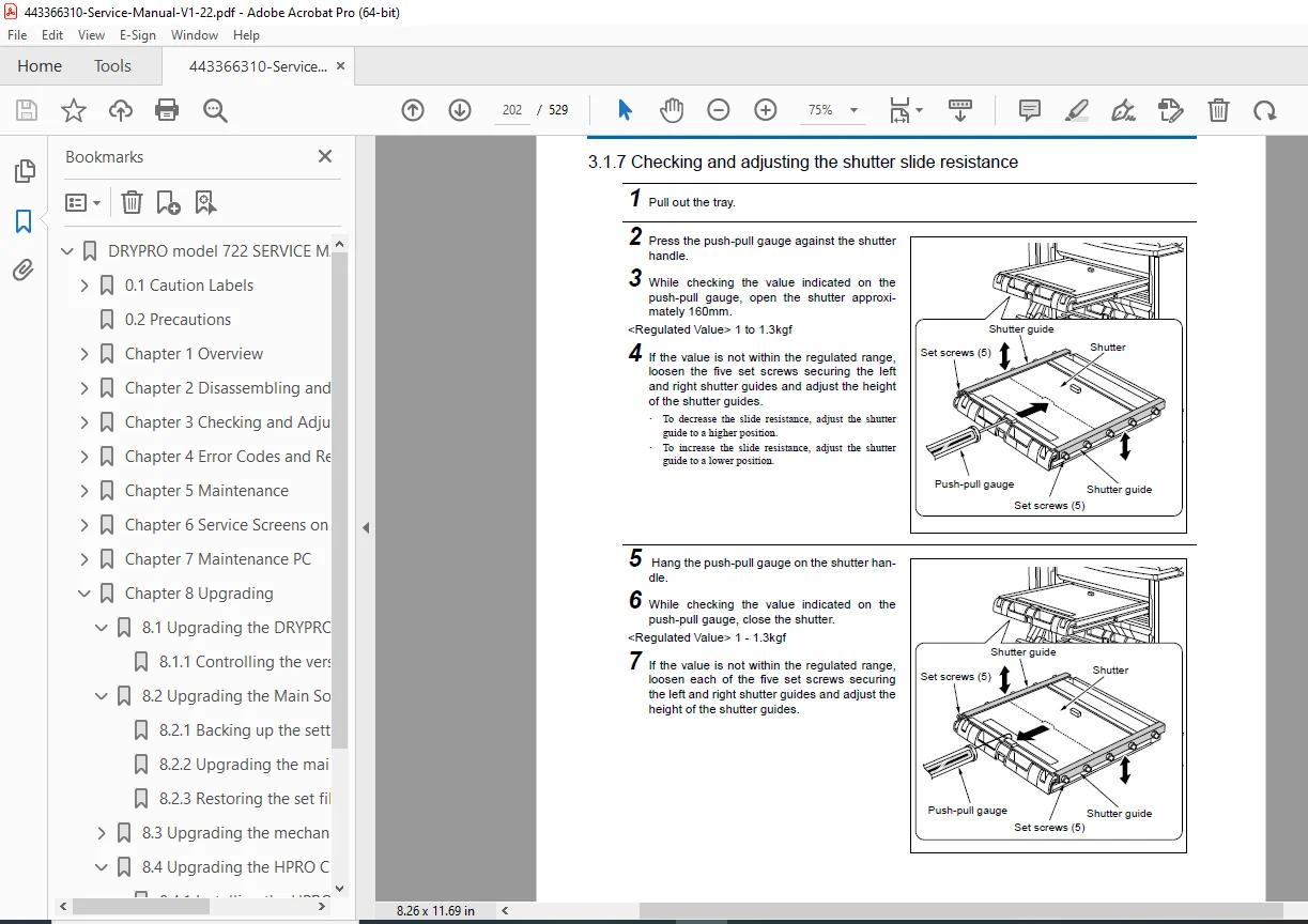
- 3.1.7 Checking and adjusting the shutter slide resistance (Page 3-10)
- 3.1.8 Adjusting the open/close position of the shutter (Page 3-11)
- 3.1.9 Adjusting the position of the shutter lock (Page 3-14)
- 3.2 Adjusting Front Transport Section (Page 3-15)
- 3.2.1 Adjusting the magnet catch of the front cover (Page 3-15)
- 3.2.2 Checking and adjusting the moving guide pusher pin (Page 3-16)
- 3.2.3 Adjusting the tension of the belt (Page 3-17)
- 3.2.4 Adjusting the left cover interlock (S2) (Page 3-18)
- 3.2.5 Adjusting lower cover interlock (S3) (Page 3-20)
- 3.3 Adjusting Lower Transport Section (Page 3-21)
- 3.3.1 Adjusting the inclination of the pusher roller (Page 3-21)
- 3.3.2 Adjusting the magnet catch (Page 3-23)
- 3.3.3 Adjusting the position of the pusher claw (Page 3-24)
- 3.3.4 Adjusting the tension of the front transport motor (M2) belt (Page 3-25)
- 3.3.5 Adjusting the tension of the film pusher motor (PM1) belt (Page 3-26)
- 3.4 Checking and adjusting Exposure Section (Page 3-27)
- 3.4.1 Adjusting the nip pressure (Page 3-27)
- 3.4.2 Cleaning the subscan unit (Page 3-29)
- 3.4.3 Cleaning the laser mirror of the optical unit (Page 3-31)
- 3.4.4 Checking the LD transmitter (PD signal) (Page 3-32)
- 3.4.5 Confirming LD radiation (IR card) and measuring the amount of radiation (Page 3-35)
- 3.4.6 Checking and adjusting the angle of the H-sync mirror (Page 3-39)
- 3.4.7 Checking the H-sync circuit board (Page 3-43)
- 3.5 Elevator Transport Section (Page 3-47)
- 3.5.1 Adjusting the open position of the nip (Page 3-47)
- 3.5.2 Adjusting the belt tension (Page 3-49)
- 3.6 Heat Processing (HPRO) Section (Page 3-50)
- 3.6.1 Adjusting the belt tension (Page 3-50)
- 3.7 Checking and Adjusting Power Supply Section (Page 3-51)
- 3.7.1 Checking the DC power voltage (Page 3-51)
- 3.7.2 Checking the AC power voltage (Page 3-52)
- 3.7.3 VR adjustment of DC power voltage (3.3V/5V) (Page 3-53)
- 3.7.4 VR adjustment of DC power (±12V/+24V) (Page 3-54)
- 3.7.5 Descriptions on the control box cover (Page 3-55)
- 3.8 Checking and Adjusting Sorter (Page 3-56)
- 3.8.1 Checking AC power voltage (Page 3-56)
- 3.8.2 Adjusting DC power voltage (5V / 12V) (Page 3-57)
- 3.8.3 Adjusting the voltage of the jam detection sensor (Page 3-59)
- 3.8.4 Adjusting belt tension (Page 3-60)
- 3.9 Correcting Images (Page 3-61)
- 3.9.1 Correcting irregularities in pitch and density of left and right sides (Page 3-61)
- 3.9.2 Stopping the time-changing density correction control (Page 3-66)
- 3.9.3 Correction of the densitometer (Page 3-68)
- 3.9.4 Correcting the densitometer correction file (Page 3-73)
- 3.9.5 Correcting the start position for writing images (Page 3-78)
- 3.1 Adjusting Supply Section (Page 3-1)
- Chapter 4 Error Codes and Remedies
- 4.1 Types of Error Codes (Page 4-1)
- 4.2 Remedies for F6000 and F6001 Errors (Page 4-2)
- 4.3 Main Errors (Page 4-3)
- 4.3.1 Error Code List (Page 4-3)
- 4.3.2 Errors that can be remedied on site (Page 4-11)
- 4.4 Mechanical Control Errors (Page 4-14)
- 4.4.1 Errors related to the main communication (007 – 013 / E4Fx) (Page 4-14)
- 4.4.2 Errors related to the outer cover (203 – 209 / E4A4x) (Page 4-15)
- 4.4.3 Errors related to ROM/RAM (052 – 067 / F4A30 – F4234) (Page 4-17)
- 4.4.4 Errors related to DownLoad (069 – 072 / F4A36 – F4A39) (Page 4-19)
- 4.4.5 Errors related to the supply section (101 – 128 / E4110 – E4227) (Page 4-20)
- 4.4.6 Errors related to the lower transport section – subscan section (135 – 149 / E4310 – E4531) (Page 4-23)
- 4.4.7 Errors related to the elevator transport section (152 – 156 / E4610 – E4621) (Page 4-29)
- 4.4.8 Errors related to the heat adjustment of the HPRO section (169 – 176 / E3000 – E3007) (Page 4-31)
- 4.4.9 Errors related to the heat processing (HPRO) section – discharge section (177 – 182 / E4710 – E4810) (Page 4-33)
- 4.4.10 Errors related to the mechanical control maintenance PC (220 – 323 / E4A3A) (Page 4-35)
- 4.4.11 Errors related to MS-DOS (501 – 597) (Page 4-37)
- 4.5 Troubles with Image Quality (Page 4-38)
- 4.5.1 Troubles with print image (Page 4-38)
- 4.5.2 Scratched or stained films (Page 4-43)
- 4.6 Troubles with Film Transport (Page 4-45)
- 4.7 Troubles Related to Mechanism (Page 4-46)
- 4.8 Other Troubles (Page 4-47)
- Chapter 5 Maintenance
- 5.1 Items for Periodical Maintenance (Page 5-1)
- 5.2 Cleaning the HPRO Section (Page 5-2)
- 5.2.1 Procedures for cleaning the HPRO section (Page 5-2)
- 5.2.2 Cleaning the FILTER case (Page 5-3)
- 5.2.3 Cleaning the periphery of the rear side of the control panel unit (Page 5-4)
- 5.2.4 Cleaning the roller cover (Page 5-5)
- 5.2.5 Cleaning the duct (Page 5-6)
- 5.2.6 Replacing the duct packing (Page 5-7)
- 5.2.7 Cleaning the inner side of the inner cover (Page 5-8)
- 5.2.8 Replacing the packing of the inner cover (Page 5-9)
- 5.2.9 Cleaning the brush (Page 5-10)
- 5.2.10 Cleaning the guide plate (entrance) (Page 5-12)
- 5.2.11 Cleaning the separation claw (Page 5-13)
- 5.2.12 Checking the operation of the separation claw roller bearings moving arm and the separation claw roller bearings (Page 5-14)
- 5.2.13 Replacing the separation claw felt (Page 5-15)
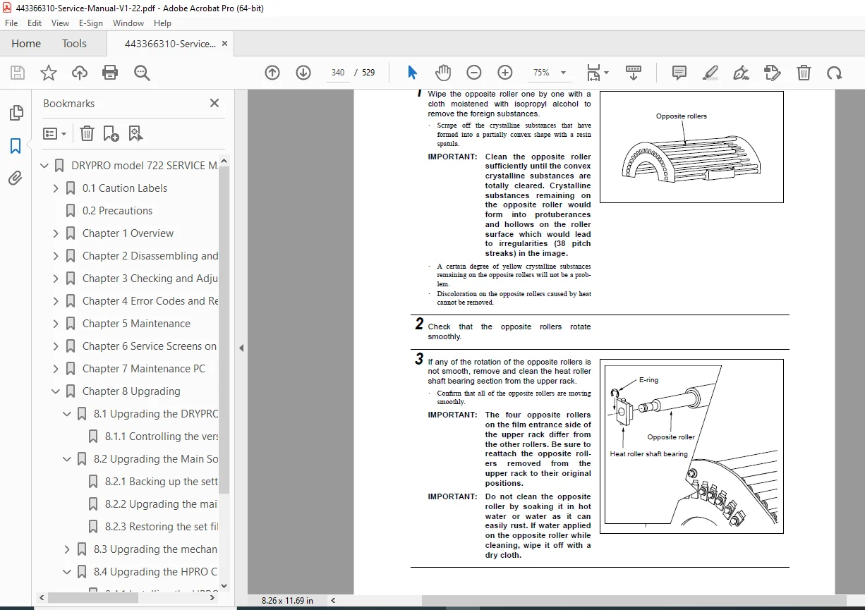
- 5.2.14 Cleaning the opposite rollers (Page 5-16)
- 5.2.15 Cleaning the slip ring (Page 5-17)
- 5.2.16 Cleaning the heat roller (Page 5-18)
- 5.2.17 Checking and adjusting the separation claw clearance (Page 5-19)
- 5.2.18 Cleaning the guide plate (cooling discharge section) (Page 5-20)
- 5.2.19 Confirming after cleaning (Page 5-21)
- 5.3 Cleaning Other Sections (Page 5-22)
- 5.3.1 Cleaning the filter (for the control box) (Page 5-22)
- 5.4 Lubrication (Page 5-23)
- 5.4.1 Heat roller drive gear (Page 5-23)
- 5.4.2 Heat roller motor assembly (Page 5-24)
- Chapter 6 Service Screens on Control Panel Section
- 6.1 Service Screens (Page 6-1)
- 6.1.1 How to display service screens (Page 6-1)
- 6.1.2 SERVICE1/4 screen (Page 6-2)
- 6.1.3 SERVICE2/4 screen (Page 6-3)
- 6.1.4 SERVICE3/4 screen (Page 6-4)
- 6.1.5 SERVICE 4/4 screen (Page 6-5)
- 6.2 CORRECT Screen (Page 6-6)
- 6.3 Test Pattern Screen (Page 6-8)
- 6.4 Version Screen (Page 6-10)
- 6.5 Flow Chart of Service Screens (Page 6-11)
- 6.1 Service Screens (Page 6-1)
- Chapter 7 Maintenance PC
- 7.1 Connecting and Starting Mechanical Control Maintenance PC (Page 7-1)
- 7.1.1 Connecting maintenance PC and DRYPRO (Page 7-1)
- 7.1.2 Starting mechanical control maintenance PC (Page 7-3)
- 7.2 Description on Screens of Mechanical Control Maintenance PC (Page 7-5)
- 7.2.1 Title screen (Page 7-5)
- 7.2.2 Menu screen (Page 7-6)
- 7.2.3 Unit test menu (Page 7-7)
- 7.2.4 Unit test; Overall transport test (Page 7-8)
- 7.2.5 Unit test; Supply test (Page 7-12)
- 7.2.6 Unit test; Lower transport section (Page 7-15)
- 7.2.7 Unit test; Elevator transport section (Page 7-17)
- 7.2.8 Unit test; Heat processing – Discharge section (Page 7-19)
- 7.2.9 Unit test; Sorter (Page 7-21)
- 7.2.10 Setup menu (Page 7-23)
- 7.2.11 Setup; Nip pressure SOL value (Page 7-24)
- 7.2.12 Setup; Pusher motor value (Page 7-25)
- 7.2.13 Setup; Optical DD motor value (Page 7-26)
- 7.2.14 Setup; Elevator transport motor value (Page 7-27)
- 7.2.15 Setup; Heat roller motor value (Page 7-28)
- 7.2.16 Setup; Discharge motor value (Page 7-29)
- 7.2.17 Setup; Supply processing value (Page 7-30)
- 7.2.18 Setup; Lower transport tray processing value (Page 7-31)
- 7.2.19 Setup; Sorter processing value (Page 7-32)
- 7.2.20 Setup; Saving setup data in file (Page 7-33)
- 7.2.21 Counter display; Menu (Page 7-34)
- 7.2.22 Counter display; Operation time display (Page 7-35)
- 7.2.23 Counter display; Film data (Page 7-36)
- 7.2.24 Load test (Page 7-38)
- 7.2.25 Input port display (Page 7-41)
- 7.2.26 RAM clear (Page 7-45)
- 7.2.27 Error count (Page 7-46)
- 7.2.28 Error log (Page 7-47)
- 7.2.29 Download (Page 7-48)
- 7.2.30 Dummy communication (HPRO dummy communication) (Page 7-49)
- 7.3 Connecting Mechanical Control Maintenance PC to Network (Page 7-51)
- 7.3.1 Network connection (Page 7-51)
- 7.3.2 Scripts and commands of Telnet (Page 7-52)
- 7.3.3 Initializing the set file (Page 7-53)
- 7.3.4 Backing up the set file (Page 7-54)
- 7.3.5 Restoring the set files (Page 7-56)
- 7.3.6 Collecting log files (Page 7-58)
- 7.3.7 Clearing the log (Page 7-62)
- 7.3.8 Check control of film type (Page 7-63)
- 7.3.9 Displaying the sum of films (Page 7-65)
- 7.3.10 Displaying the filter exchange time (Page 7-66)
- 7.4 Install Software (Page 7-67)
- 7.4.1 Before starting install software (Page 7-67)
- 7.4.2 Main screen (Page 7-68)
- 7.4.3 File menu (Page 7-69)
- 7.4.4 Software menu (Page 7-71)
- 7.4.5 Reset menu (Page 7-72)
- 7.4.6 Maintenance menu (Page 7-73)
- 7.4.7 Help menu (Page 7-76)
- 7.4.8 System screen (Page 7-77)
- 7.4.9 System dialogue (Page 7-78)
- 7.4.10 Channel setting screen 1 (Page 7-82)
- 7.4.11 Channel setting screen 2 (Page 7-83)
- 7.4.12 SCU-DICOM dialogue (Page 7-84)
- 7.4.13 SCU-Film dialogue (Page 7-85)
- 7.4.14 SCU-Format dialogue (Page 7-88)
- 7.4.15 SCU-LUT dialogue (Page 7-92)
- 7.4.16 Stamp setting screen (Page 7-93)
- 7.4.17 SCU-Stamp-Strings dialogue (Page 7-94)
- 7.4.18 SCU-Stamp-Information dialogue (Page 7-95)
- 7.4.19 SCU-Stamp-Format dialogue (Page 7-96)
- 7.4.20 Correction screen (Page 7-97)
- 7.4.21 Correction-Smooth dialogue (Page 7-98)
- 7.1 Connecting and Starting Mechanical Control Maintenance PC (Page 7-1)
- Chapter 8 Upgrading
- 8.1 Upgrading the DRYPRO 722 (Page 8-1)
- 8.1.1 Controlling the version of the DRYRO 722 (Page 8-1)
- 8.2 Upgrading the Main Software (Page 8-2)
- 8.2.1 Backing up the setting file (Page 8-2)
- 8.2.2 Upgrading the main software (Page 8-4)
- 8.2.3 Restoring the set files (Page 8-6)
- 8.3 Upgrading the mechanical control software (Page 8-8)
- 8.3.1 How to upgrade (Page 8-8)
- 8.3.2 When failing a download (Page 8-9)
- 8.3.3 When the Flash ROM does not activate (Page 8-10)
- 8.4 Upgrading the HPRO CPU (Page 8-11)
- 8.4.1 Installing the HPRO software (Page 8-11)
- 8.4.2 Initializing and setting the offset value (Page 8-15)
- 8.5 Upgrading the Control Panel Software (Page 8-16)
- 8.5.1 Replacing the ROM in the control section (Page 8-16)
- 8.1 Upgrading the DRYPRO 722 (Page 8-1)
- Chapter 9 Appendix
- 9.1 Explanation of Sucker Operation (Page 9-1)
- 9.2 Maintenance Information (Page 9-3)
- 9.3 File Names and the Timing to Create Log Files (Page 9-5)
- 9.3.1 Automatic creation of log files (Page 9-5)
- 9.3.2 Operations upon starting log command (Page 9-6)
- 9.4 Using telnet and ftp (Page 9-7)
- 9.4.1 Using telnet (Page 9-7)
- 9.4.2 Using ftp (Page 9-9)
- 9.5 Board Layout (Page 9-12)
- 9.5.1 Supply volume board (Page 9-12)
- 9.5.2 Supply drive board (Page 9-14)
- 9.5.3 H-sync circuit board (Page 9-16)
- 9.5.4 Heat roller motor driver board (Page 9-17)
- 9.5.5 HPRO CPU circuit board (Page 9-18)
- 9.5.6 HPRO power circuit board (Page 9-20)
- 9.5.7 HPRO I/F board (Page 9-21)
- 9.5.8 Control panel board (Page 9-22)
- 9.5.9 Power I/F board (Page 9-23)
- 9.5.10 Print control board (Page 9-25)
- 9.5.11 DENS I/F circuit board (Page 9-27)
- 9.5.12 Mechanical control circuit board (Page 9-28)
- 9.5.13 Relay board (Page 9-30)
- 9.6 Timing Chart (Page 9-31)
- 9.6.1 Pick up operation (Page 9-31)
- 9.6.2 Supply operation–Front transport–Feed 1 operation (Page 9-32)
- 9.6.3 Exposure operation–Elevator transportation operation (Page 9-33)
- 9.6.4 HPRO section transport–Discharge section transport operation (Page 9-35)
- 9.6.5 Sorter transport operation (Page 9-36)
- 9.6.6 Bar code reading & Barrier taking-up (Page 9-37)
- 9.7 Overall Wiring Diagram (1/3) (Page 9-38)
- 9.8 Overall Wiring Diagram (2/3) (Page 9-39)
- 9.9 Overall Wiring Diagram (3/3) (Page 9-40)
- 9.10 Sorter Overall Wiring Diagram (Page 9-41)
No separate bookmarks or index are present beyond the table of contents. This Konica Minolta DRYPRO 722 service manual PDF ensures effective repairs with board layouts and wiring diagrams.
File Details
- Manual Name: DRY LASER IMAGER DRYPRO model 722 SERVICE MANUAL
- Models Covered: DRYPRO 722, LiS-722 Sorter
- Year: 2001
- Manual PDF Quality: High-resolution scan with clear text, diagrams, and illustrations
- No of Pages: 529