Description
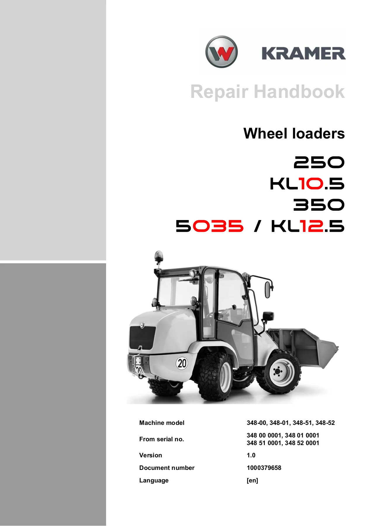
Kramer 250 / 350 / 5035 / KL10.5 / KL12.5 Wheel Loader Repair Handbook
This is the Kramer Repair Handbook (RHB 348-00/01) covering the 250, 350, 5035, KL10.5 and KL12.5 wheel loaders. It is a working workshop document built around photographed disassembly and assembly sequences, with the torque values, capacities and safety instructions a technician needs in front of the machine. Every procedure is laid out as a numbered operation with image callouts, so a single sub-task such as replacing an oil pressure switch, a coolant temperature sensor or a wheel motor bearing can be followed on its own without reading the entire chapter.
File Details
- Manual type: Repair Handbook (workshop manual)
- Brand: Kramer
- Models covered: 250, 350, 5035, KL10.5, KL12.5
- Document number: 1000379658 (RHB 348-00/01)
- Version: 1.0
- Date: 05/2017
- Language: English [en]
- Format: PDF
- Page count: 461
- Serial number groups: 348-00, 348-01, 348-51, 348-52
- Serial number ranges: 348 00 0001, 348 01 0001, 348 51 0001, 348 52 0001
Chapters Covered
- E Introduction — notes on the repair manual, safety instructions, safety symbols and signal words, tightening torques (general, metric coarse-pitch thread, metric fine-pitch thread, hydraulic and climate screw connections, banjo bolts, adjustable hydraulic screw struts, brake line screw connections, worm drive and spring-loaded hose clamps)
- 1 Maintenance — maintenance plan, service intervals, fluids and lubricants, diesel fuel specification, coolant mixing, biodegradable oil notes, maintenance accesses, machine fuses, cleaning and maintenance, lubrication work, fuel system, engine lube oil system, cooling system, air filter, V-belt/toothed belt, hydraulic system, pressure accumulator, electrical system, heating and ventilation, washer system, braking system, tyres, attachments, trailer coupling, machine preservation
- 2 Engine — removing/installing the engine, Centaflex coupling, exhaust system and silencer, starter M001, alternator G001, cut-off solenoid, oil pressure switch, fuel tank, tank sensor B001, accelerator pedal, throttle cable adjustment
- 3 Cooling — oil-to-water cooler, fan wheel, radiator separating plate, coolant temperature sensor, coolant hoses
- 4 Traveling drive — variable displacement pump, wheel motors, distributing block
- 6 Brakes — brake/inching pedal, inching valve, parking brake valve
- 7 Steering — steering column, hydrostatic steering, priority valve, steering cylinder 018/019 including sealing
- 8 Hydraulics — control valve and secondary valves, hydraulic oil tank, filter housing, load stabiliser, pressure accumulator load stabiliser, 3rd control circuit, quickhitch lock solenoid valve, pilot control pressure accumulator, additional control circuit, work hydraulics tandem pump, lift cylinder, tilt cylinder, lock ram, telescopic boom (rocker arm, tilt rod, bearing, boom)
- 9 Electrical system — control lever, front wiper, rear wiper, steering column control lever
- 12 Trim — engine cover, trims inside the cab, joystick trim, wheel covers, counterweights
- 14 Cab — cab removal and installation, floor assembly, cabin bearing, operator seat, front window, rear window, side window
- 15 Heating/air conditioning — heating unit, heating regulator
Across these chapters the handbook walks through component-level work on the diesel engine and its mountings, the combined water and oil radiator, the hydrostatic travel drive and its variable displacement pump, the wheel motors with their brake and bearing pins, the steering orbitrol and priority valve, the working hydraulics including lift, tilt and quickhitch lock cylinders, and the full cab and floor assembly. Torque settings are given alongside the operations rather than buried in an appendix, and the introduction carries the general tightening torque tables plus the specific hydraulic screw connection values used throughout.
Complete PDF Bookmark Tree
Complete Bookmarks
The complete bookmarks in the “Kramer 250 350 5035 KL10.5 KL12.5 Wheel Loaders Repair Handbook 1000379658” are as follows:
+Repair Handbookp. 1
+E Introductionp. 3
+E.1 Notes on the repair manualp. 4
Working with the repair manualp. 4
Explanation of symbols and abbreviationsp. 4
Repair instructionsp. 6
Required tools and screw connectionsp. 7
Procedurep. 7
+E.2 Safety instructionsp. 8
Pay particular attention to the followingp. 8
Safety symbols and signal wordsp. 8
Safety and accident prevention regulationsp. 9
+E.3 Tightening torquesp. 14
General tightening torquesp. 14
Specific tightening torquesp. 14
Torque values for metric coarse-pitch threadp. 15
Torque values for metric fine-pitch threadp. 16
Tightening torques for hydraulic screw connections and climate screw connections with taper connections and O-rings DIN 3865p. 17
Tightening torques for hydraulic screw connections with olive DIN 3861p. 18
Tightening torques for hydraulic system screw-in spud SDSp. 19
Tightening torques for hydraulics rotating screw connectionsp. 22
Tightening torques for banjo bolts DIN 7643p. 22
Tightening torques for adjustable hydraulic screw struts SDEp. 23
Tightening torques for brake line screw connectionsp. 25
Tightening torques for worm drive hose clampsp. 25
Tightening torques for spring-loaded worm drive hose clampsp. 25
+1 Maintenancep. 26
+1.1 Maintenance preparation, noticesp. 27
Information on maintenancep. 27
Safety instructions concerning maintenance workp. 28
Parking the vehiclep. 29
Jack up the vehiclep. 29
Disconnect/switch on batteryp. 30
Quick fastener of battery terminal (option)p. 31
Battery isolator switch S008 (option)p. 32
Unclip/clip on the battery earth strapp. 33
Safety prop for loader unitp. 34
Breather filter/vacuum gagep. 35
+1.2 Maintenance overviewp. 36
Maintenance planp. 36
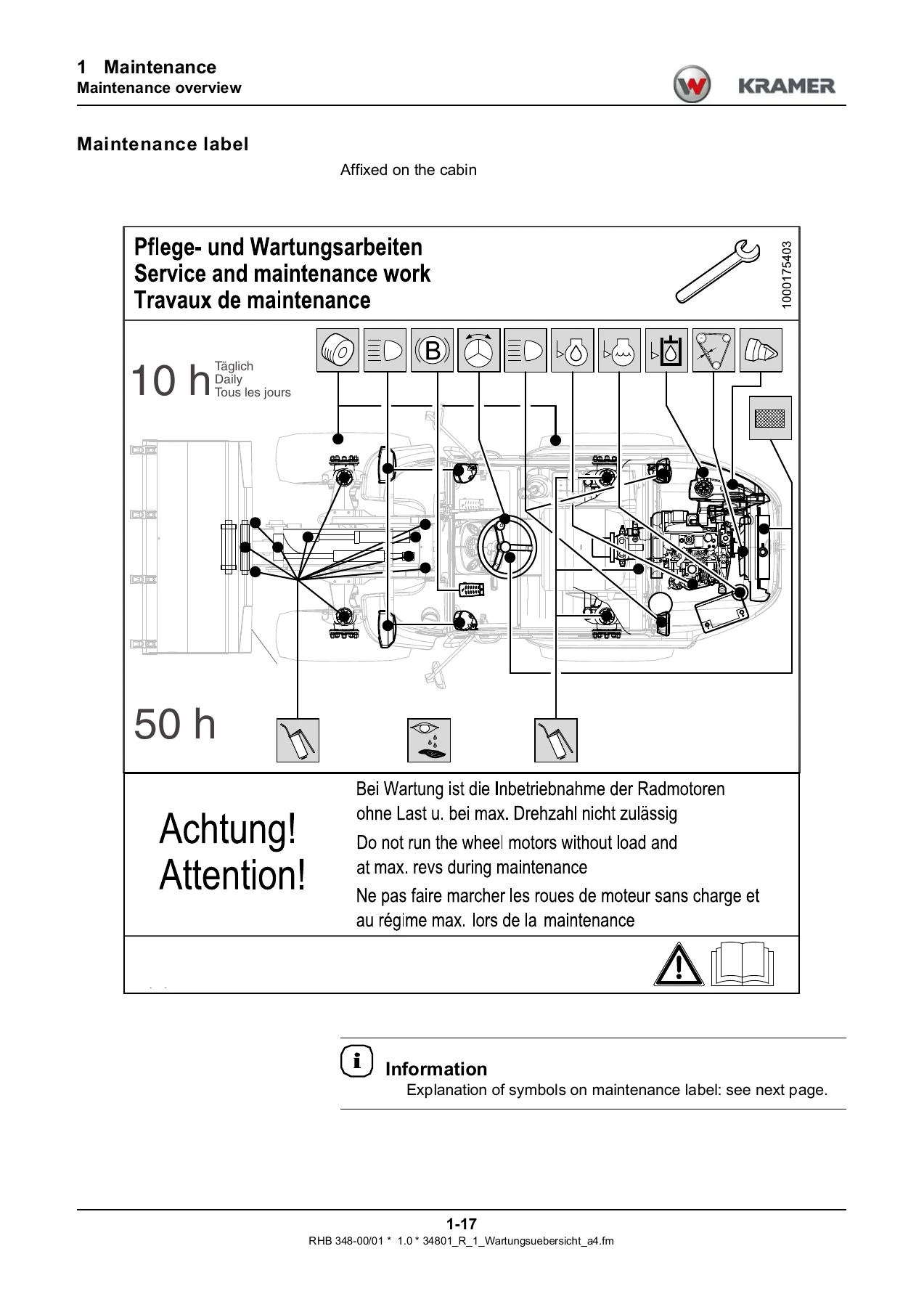
Maintenance labelp. 43
Explanation of symbols on the maintenance labelp. 44
+1.3 Fluids and lubricantsp. 45
Fluids and lubricants (overview)p. 45
Diesel fuel specificationp. 46
Coolantp. 47
Important notice about operation with biodegradable oilsp. 48
+1.4 Maintenance accessesp. 49
Engine coverp. 49
Engine bayp. 49
Side boxp. 50
Machine fusesp. 51
Relaysp. 52
+1.5 Cleaning and maintenancep. 53
Cleaning inside the cabinp. 55
Cleaning the seat belt (lap belt)p. 56
Cleaning the pedalsp. 57
Cleaning the exterior of the vehiclep. 58
Cleaning the engine and the engine compartmentp. 59
Checking screw connectionsp. 59
Checking pivots and hingesp. 59
+1.6 Lubrication workp. 60
Preparationsp. 60
Lubricating the rear axle oscillation-type bearingp. 60
Lubricating the wheel motor bearings (front and rear axle)p. 61
Lubricating the door arrester (option)p. 61
Lubricating the loader unitp. 62
Centralised grease pointp. 64
+1.7 Fuel systemp. 65
Safety instructions for refuellingp. 65
Stationary fuel pumpsp. 66
Refuellingp. 67
Drain fuelp. 68
Bleeding the fuel systemp. 68
Check fuelprefilter/drain waterp. 69
Replace the fuel filterp. 70
+1.8 Engine lube oil systemp. 71
Important safety instructionsp. 71
Checking the engine oil levelp. 72
Adding engine oilp. 73
Changing engine oilp. 74
Replacing the engine oil filterp. 76
+1.9 Cooling systemp. 77
Safety instructionsp. 77
Information on inspection and cleaning work on the cooling systemp. 78
Checking the coolant levelp. 79
Adding coolantp. 80
Draining/replacing coolantp. 81
Cleaning the radiatorp. 83
+1.10 Air filterp. 84
Important information on cleaning the air filterp. 84
Cleaning the dust valvep. 85
Replacing the filter cartridgep. 86
+1.11 V-belt/toothed beltp. 89
Checking/retensioning the V-belt (alternator/water pump)p. 89
Changing the V-belt (alternator/water pump)p. 91
+1.12 Hydraulic systemp. 94
Important informationp. 94
Monitoring the hydraulic oil and the return filterp. 95
Checking the hydraulic oil levelp. 96
Adding hydraulic oilp. 97
Replacing hydraulic oilp. 99
Replacing the hydraulic oil suction return filterp. 101
Hydraulic oil tank – change the breather filterp. 102
Checking the hydraulic system for leaksp. 103
Checking hydraulic hoses for damage and ageingp. 104
+1.13 Pressure accumulatorp. 105
Check membrane pressure accumulatorp. 106
+1.14 Electrical systemp. 109
Safety instructions regarding the batteryp. 109
Keeping the battery in good statep. 110
Disposal of old batteryp. 110
Checking/replacing the batteryp. 111
Inspections and maintenance on the electrical system at regular intervalsp. 113
Checking the alternatorp. 113
Checking/replacing fusesp. 114
Checking/replacing relaysp. 115
+1.15 Heating, ventilationp. 116
Important information on cabin ventilation (option with closed cabin)p. 116
Cleaning/replacing the fine-dust filterp. 117
+1.16 Washer systemp. 119
+1.17 Braking systemp. 120
Important safety instructionsp. 120
Checking the parking brakep. 121
+1.18 Tyresp. 122
Important informationp. 122
Tyre checkp. 122
Removing the wheelsp. 123
Mounting the wheelsp. 124
1.19 Attachmentsp. 125
+1.20 Trailer couplingp. 126
Automatic trailer coupling (option)p. 126
+1.21 Machine preservationp. 128
Important information on anticorrosion protection (option)p. 128
Measures for maintaining anticorrosive protectionp. 129
Cleaningp. 129
Applying the protective anticorrosion coatingp. 130
Treatment of oxidised surfacesp. 130
+2 Enginep. 131
+2.1 Enginep. 132
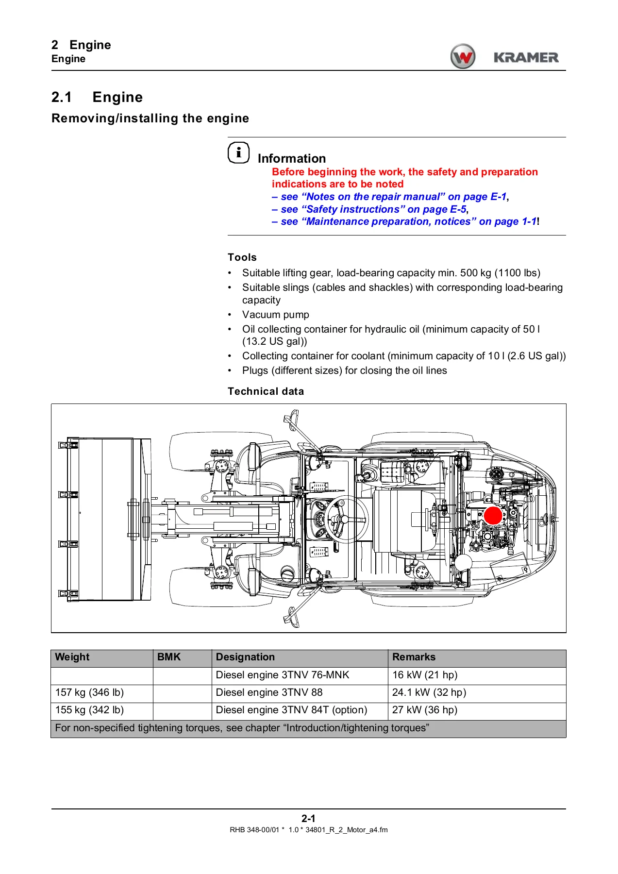
Removing/installing the enginep. 132
+2.2 Centaflex-couplingp. 146
Remove/install Centaflex couplingp. 146
+2.3 Exhaust systemp. 151
Removing / installing exhaust silencerp. 151
+2.4 Starter M001p. 154
Remove / install motor starterp. 154
+2.5 Alternator G001p. 157
Remove/install alternatorp. 157
+2.6 Cut-off solenoidp. 160
Remove / install cut-off solenoidp. 160
+2.7 Oil pressure switchp. 165
Remove / install oil pressure switchp. 165
+2.8 Fuel tankp. 167
Remove / install fuel tankp. 167
+2.9 Tank sensor B001p. 173
Removing/installing fuel sensor B001p. 173
+2.10 Accelerator pedalp. 176
Remove / install accelerator pedalp. 176
+2.11 Throttle cablep. 180
Remove / install throttle cablep. 180
+3 Coolingp. 184
+3.1 Oil-to-water-coolerp. 185
Remove/install oil-to-water-coolerp. 185
+3.2 Fan wheelp. 191
Removing / installing fan impellerp. 191
+3.3 Radiator separating platep. 194
Remove / install radiator separating platep. 194
+3.4 Coolant temperature sensorp. 199
Remove / install temperature sensorp. 199
+3.5 Coolant hosesp. 202
Remove/install coolant hosesp. 202
+4 Traveling drivep. 206
+4.1 Variable displacement pumpp. 207
Remove/install variable displacement pumpp. 207
+4.2 Wheel motorsp. 217
Removing / installing wheel motorsp. 217
+4.3 Distributing blockp. 224
Remove/install distributor blockp. 224
+6 Brakesp. 234
+6.1 Brake/inching pedalp. 235
Remove / install brake/inching pedalp. 235
+6.2 Inching valvep. 239
Remove / install inching valvep. 239
+6.3 Parking brake valvep. 242
Removing / installing parking brake valvep. 242
+7 Steeringp. 245
+7.1 Steering columnp. 246
Completely disassembling / installing the steering columnp. 246
+7.2 Hydrostatic steeringp. 249
Install / remove hydrostatic steeringp. 249
+7.3 Priority valvep. 252
Removing/installing priority valvep. 252
+7.4 Steering cylinder 018/019p. 258
Remove / install steering cylinderp. 258
Sealing steering cylindersp. 263
+8 Hydraulicsp. 265
+8.1 Control valvep. 266
Remove / install control unitp. 266
Remove / install secondary valvesp. 275
+8.2 Hydraulic oil tankp. 280
Remove / install hydraulic oil tankp. 280
+8.3 Filter housingp. 288
Remove / install filter housingp. 288
+8.4 Load stabiliserp. 293
Removing/installing solenoid valve load stabiliserp. 293
+8.5 Pressure accumulator load stabiliserp. 298
Removing/installing pressure accumulator load stabiliserp. 298
+8.6 3rd control circuitp. 301
Remove / install solenoid valve pilot control unitp. 301
Removing/installing the solenoid valve quickhitch lockp. 307
+8.7 Pilot control pressure accumulatorp. 311
Removing/installing pressure accumulator pilot controlp. 311
+8.8 Additional control circuitp. 314
Removing/installing additional control circuit for changeover valvep. 314
Removing/installing additional control circuit for valve blockp. 317
+8.9 Work hydraulics tandem pumpp. 322
Remove/install tandem pumpp. 322
+8.10 Lifting cylinderp. 327
Removing/installing the lift cylinderp. 327
+8.11 Tilt cylinderp. 334
Removing/installing the tilt cylinderp. 334
+8.12 Lock ram (quickhitch facility)p. 341
Removing/installing lock ramp. 341
+8.13 Telescopic boomp. 347
Remove/install rocker armp. 347
Remove / install tilt rodp. 351
Remove / install bearingp. 354
Remove / install boomp. 357
+9 Electrical systemp. 369
+9.1 Control leverp. 370
Remove / install control leverp. 370
+9.2 Front wiperp. 373
Remove / install the wiper motorp. 373
+9.3 Rear wiperp. 376
Remove / install the wiper motorp. 376
+9.4 Steering column control leverp. 381
Remove / install steering column control leverp. 381
+12 Trimp. 385
+12.1 Engine coverp. 386
Remove/install engine coverp. 386
+12.2 Trims inside the cabp. 388
Removing/installing steering column trimsp. 388
Remove/install joystick trimp. 395
+12.3 Wheel coversp. 400
Remove/install wheel cover (front right)p. 400
Remove / install wheel cover back right / leftp. 403
+12.4 Counterweightsp. 406
Remove / install counterweights left / rightp. 406
+14 Cabp. 409
+14.1 Cabp. 410
Remove / install cabinp. 410
+14.2 Floor assemblyp. 417
Remove / install floor assemblyp. 417
+14.3 Cabin bearingp. 435
Remove / install rubber insertp. 435
+14.4 Operator seatp. 441
Remove/install operator seatp. 441
+14.5 Front windowp. 444
Remove / install front windowp. 444
+14.6 Rear windowp. 447
Remove / install rear windowp. 447
+14.7 Side windowp. 450
Remove/install side windowp. 450
+15 Heating/air conditioningp. 452
+15.1 Heating unitp. 453
Removing / installing heating unitp. 453
+15.2 Heating regulatorp. 457
Remove / install heating regulatorp. 457
What This Repair Handbook Enables
The document supports real repair work rather than routine servicing alone. You can lift the diesel engine out of the engine vat and reinstall it on its bearings, separate the Centaflex coupling, reseal the lift and tilt cylinders, replace the wheel motor bearing pins, rebuild the steering cylinder with its guide bushing and seal kit, remove and pre-assemble the control valve screwed fittings, and drain, flush and refill the hydraulic oil tank at the correct capacities. Diagnostic coverage includes the maintenance display on the air filter, the return filter and oil temperature indicator lights, hydraulic hose age inspection against DIN 20066 part 5, and membrane accumulator pressure checking with a filling and testing device.
Working from the correct procedures and the printed torque values matters on a machine like this — the hydrostatic drive and the multi-disc brake are safety-critical, and the introduction states plainly that repairs to the hydraulic system and to the axles and drive should be carried out by specialist workshops. Having the manufacturer’s own sequence, seal orientation notes, locking compound callouts (Loctite 243, 511, 638) and component weights in front of you removes guesswork from the job.
Delivery is instant. The Repair Handbook arrives as a PDF download with no shipping and no waiting, ready to open on a workshop laptop, tablet or phone. Print the pages you need for the job in front of you and keep the rest on file.


Reviews
There are no reviews yet.