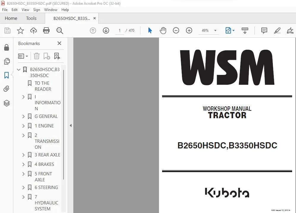
Kubota B2650HSDC B3350HSDC Tractor Workshop Manual – PDF DOWNLOAD
Original price was: $89.95.$28.95Current price is: $28.95.
Kubota B2650HSDC B3350HSDC Tractor Workshop Manual – PDF DOWNLOAD
Description
Kubota B2650HSDC B3350HSDC Tractor Workshop Manual – PDF DOWNLOAD
DESCRIPTION:
Kubota B2650HSDC B3350HSDC Tractor Workshop Manual – PDF DOWNLOAD
TO THE READER
This Workshop Manual tells the servicing personnel about the mechanism, servicing and
maintenance of the B2650HSDC and B3350HSDC. It contains 4 parts: “Information”, “General”,
“Mechanism” and “Servicing”.
? Information
This section primarily contains information below.
• Safety First
• Safety Decal
• Specifications
• Dimensions
? General
This section primarily contains information below.
• Engine Identification
• Model Identification
• General Precautions
• Maintenance Check List
• Check and Maintenance
• Special Tools
? Mechanism
This section contains information on the structure and the function of the unit. Before you continue
with the subsequent sections, make sure that you read this section.
Refer to the latest version of Workshop Manual (Code No. 9Y021-01870 / 9Y021-18200) for the
diesel engine / tractor mechanism that this workshop manual does not include.
? Servicing
This section primarily contains information below.
• Troubleshooting
• Servicing Specifications
• Tightening Torques
• Checking, Disassembling and Servicing
All illustrations, photographs and specifications contained in this manual are of the newest
information available at the time of publication.
KUBOTA reserves the right to change all information at any time without notice.
Since this manual includes many models, information or illustrations and photographs can show
more than one model.
TABLE OF CONTENTS:
Kubota B2650HSDC B3350HSDC Tractor Workshop Manual – PDF DOWNLOAD
B2650HSDC,B3350HSDC…………………………………………………………………………………….. 1
TO THE READER………………………………………………………………………………………. 2
I INFORMATION………………………………………………………………………………………. 3
INFORMATION…………………………………………………………………………………….. 4
1. SAFETY FIRST……………………………………………………………………………… 5
2. SAFETY DECALS…………………………………………………………………………….. 8
3. SPECIFICATIONS……………………………………………………………………………. 12
4. TRAVELING SPEEDS………………………………………………………………………….. 13
5. DIMENSIONS……………………………………………………………………………….. 14
G GENERAL………………………………………………………………………………………….. 15
GENERAL………………………………………………………………………………………… 16
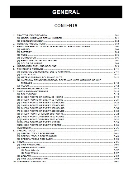
1. TRACTOR IDENTIFICATION…………………………………………………………………….. 17
[1] MODEL NAME AND SERIAL NUMBER…………………………………………………………… 17
[2] CYLINDER NUMBER………………………………………………………………………. 18
2. GENERAL PRECAUTIONS……………………………………………………………………….. 19
3. HANDLING PRECAUTIONS FOR ELECTRICAL PARTS AND WIRING………………………………………….. 20
[1] WIRING………………………………………………………………………………. 20
[2] BATTERY……………………………………………………………………………… 22
[3] FUSE………………………………………………………………………………… 22
[4] CONNECTOR……………………………………………………………………………. 22
[5] HANDLING OF CIRCUIT TESTER…………………………………………………………….. 23
[6] COLOR OF WIRING………………………………………………………………………. 24
4. LUBRICANTS, FUEL AND COOLANT……………………………………………………………….. 25
5. TIGHTENING TORQUES………………………………………………………………………… 27
[1] GENERAL USE SCREWS, BOLTS AND NUTS……………………………………………………… 27
[2] STUD BOLTS…………………………………………………………………………… 27
[3] METRIC SCREWS, BOLTS AND NUTS………………………………………………………….. 28
[4] AMERICAN STANDARD SCREWS, BOLTS AND NUTS WITH UNC OR UNF THREADS…………………………… 28
[5] PLUGS……………………………………………………………………………….. 28
6. MAINTENANCE CHECK LIST…………………………………………………………………….. 29
7. CHECK AND MAINTENANCE……………………………………………………………………… 31
[1] DAILY CHECK………………………………………………………………………….. 31
[2] CHECK POINTS OF INITIAL 50 HOURS……………………………………………………….. 35
[3] CHECK POINTS OF EVERY 50 HOURS…………………………………………………………. 37
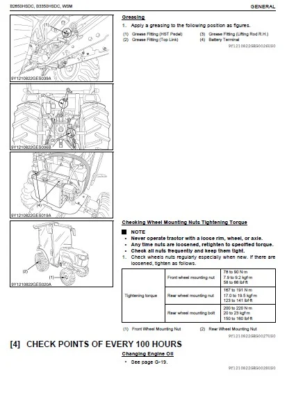
[4] CHECK POINTS OF EVERY 100 HOURS………………………………………………………… 38
[5] CHECK POINTS OF EVERY 200 HOURS………………………………………………………… 43
[6] CHECK POINTS OF EVERY 300 HOURS………………………………………………………… 46
[7] CHECK POINTS OF EVERY 400 HOURS………………………………………………………… 48
[8] CHECK POINT OF EVERY 800 HOURS…………………………………………………………. 48
[9] CHECK POINT OF EVERY 1500 HOURS………………………………………………………… 48
[10] CHECK POINT OF EVERY 3000 HOURS……………………………………………………….. 48
[11] CHECK POINTS OF EVERY 1 YEAR………………………………………………………….. 49
[12] CHECK POINTS OF EVERY 2 YEARS…………………………………………………………. 50
[13] OTHERS……………………………………………………………………………… 52
8. SPECIAL TOOLS…………………………………………………………………………….. 57
[1] SPECIAL TOOLS FOR ENGINE………………………………………………………………. 57
[2] SPECIAL TOOLS FOR TRACTOR……………………………………………………………… 65
[3] SPECIAL TOOLS FOR CABIN……………………………………………………………….. 69
9. TIRES……………………………………………………………………………………. 72
[1] TIRE PRESSURE………………………………………………………………………… 72
[2] TREAD ADJUSTMENT……………………………………………………………………… 73
(1) Front Wheels……………………………………………………………………… 73
(2) Rear Wheels………………………………………………………………………. 73
[3] BALLAST……………………………………………………………………………… 74
[4] TIRE LIQUID INJECTION…………………………………………………………………. 75
10. IMPLEMENT LIMITATIONS…………………………………………………………………….. 77
1 ENGINE…………………………………………………………………………………………… 79
MECHANISM………………………………………………………………………………………. 80
1. ENGINE BODY………………………………………………………………………………. 81
[1] CLOSED BREATHER………………………………………………………………………. 81
[2] HALF-FLOATING HEAD COVER………………………………………………………………. 81
[3] ENGINE CONTROL SYSTEM [V1505-T-E4]……………………………………………………… 82
[4] ELECTRONIC GOVERNOR [V1505-T-E4]……………………………………………………….. 82
[5] GOVERNOR [D1305-E4]…………………………………………………………………… 83
2. REFORMER AND AFTER TREATMENT DEVICES………………………………………………………… 85
[1] REFORMER…………………………………………………………………………….. 85
[2] AFTER TREATMENT DEVICES……………………………………………………………….. 86
[3] DPF REGENERATION SYSTEM……………………………………………………………….. 88
(1) Regeneration Mode…………………………………………………………………. 88
(2) Indicator and Switch Lamp………………………………………………………….. 89
(3) Warning Level…………………………………………………………………….. 90
SERVICING………………………………………………………………………………………. 92
1. TROUBLESHOOTING…………………………………………………………………………… 93
2. SERVICING SPECIFICATIONS…………………………………………………………………… 97
3. TIGHTENING TORQUES…………………………………………………………………………103
[1] TRACTOR SECTION……………………………………………………………………….103
[2] ENGINE SECTION………………………………………………………………………..103
4. CHECKING, DISASSEMBLING AND SERVICING………………………………………………………..104
[1] CHECKING AND ADJUSTING…………………………………………………………………104
(1) Engine Body……………………………………………………………………….104
(2) Lubricating System…………………………………………………………………107
(3) Cooling System…………………………………………………………………….107
(4) Fuel System……………………………………………………………………….109
(5) Electrical System………………………………………………………………….112
(6) Turbocharger (V1505-T-E4)…………………………………………………………..116
[2] DISASSEMBLING AND ASSEMBLING……………………………………………………………117
(1) DPF Muffler……………………………………………………………………….117
(2) Separating Engine from Clutch Housing………………………………………………..118
(3) Separating Engine from Front Axle Frame………………………………………………123
(4) External Components………………………………………………………………..124
(5) Cylinder Head and Valve…………………………………………………………….125
(6) Gear Case and Timing Gears………………………………………………………….129
(7) Piston and Connecting Rod…………………………………………………………..133
(8) Flywheel and Crankshaft…………………………………………………………….136
[3] SERVICING…………………………………………………………………………….140
(1) Cylinder Head and Valve…………………………………………………………….140
(2) Timing Gears, Camshaft and Governor Gear……………………………………………..145
(3) Piston and Connecting Rod…………………………………………………………..148
(4) Crankshaft………………………………………………………………………..151
(5) Cylinder………………………………………………………………………….157
(6) Oil Pump………………………………………………………………………….158
2 TRANSMISSION………………………………………………………………………………………159
MECHANISM……………………………………………………………………………………….160
1. STRUCTURE…………………………………………………………………………………161
2. FRONT CASE………………………………………………………………………………..162
3. HYDROSTATIC TRANSMISSION……………………………………………………………………163
[1] STRUCTURE…………………………………………………………………………….163
[2] PUMP AND MOTOR………………………………………………………………………..165
[3] OIL FLOW AND VALVES……………………………………………………………………166
[4] CONTROL LINKAGE……………………………………………………………………….173
4. CRUISE CONTROL…………………………………………………………………………….174
[1] CRUISE CONTROL LINKAGE…………………………………………………………………174
(1) Cruise Control…………………………………………………………………….174
(2) Cruise Control Release……………………………………………………………..175
5. RANGE GEAR SHIFT SECTION……………………………………………………………………176
6. FRONT WHEEL DRIVE SECTION…………………………………………………………………..177
7. PTO SYSTEM………………………………………………………………………………..178
[1] STRUCTURE…………………………………………………………………………….178
[2] REAR PTO SECTION………………………………………………………………………179
[3] REAR PTO / MID-PTO SECTION……………………………………………………………..180
[4] MID-PTO SECTION……………………………………………………………………….181
[5] INDEPENDENT PTO……………………………………………………………………….182
(1) Hydraulic Circuit………………………………………………………………….182
(2) Independent PTO Control Valve……………………………………………………….183
(3) Independent PTO Clutch……………………………………………………………..184
(4) Independent PTO Lever “Engaged”……………………………………………………..185
(5) Independent PTO Lever “Disengaged”…………………………………………………..186
8. DIFFERENTIAL GEAR SYSTEM……………………………………………………………………187
[1] DIFFERENTIAL FUNCTION………………………………………………………………….187
[2] DIFFERENTIAL LOCK……………………………………………………………………..188
SERVICING……………………………………………………………………………………….189
1. TROUBLESHOOTING……………………………………………………………………………190
2. SERVICING SPECIFICATIONS……………………………………………………………………194
3. TIGHTENING TORQUES…………………………………………………………………………196
4. CHECKING, DISASSEMBLING AND SERVICING………………………………………………………..197
[1] CHECKING AND ADJUSTING…………………………………………………………………197
(1) HST………………………………………………………………………………197
(2) Independent PTO Control Valve……………………………………………………….201
[2] PREPARATION…………………………………………………………………………..202
(1) Separating Cabin From Tractor……………………………………………………….202
[3] DISASSEMBLING AND ASSEMBLING……………………………………………………………207
(1) Separating Engine and Clutch Housing…………………………………………………207
(2) Front Case………………………………………………………………………..208
(3) Hydraulic Transmission (HST)………………………………………………………..209
(4) PTO Clutch Case……………………………………………………………………219
(5) Bevel Pinion Shaft…………………………………………………………………220
(6) Range Gear Shaft…………………………………………………………………..220
(7) Front Wheel Drive Shaft…………………………………………………………….222
(8) Independent PTO Clutch Shifter………………………………………………………223
(9) Independent PTO Clutch……………………………………………………………..225
(10) Mid-PTO Section…………………………………………………………………..229
(11) Differential Gear Section………………………………………………………….231
[4] SERVICING…………………………………………………………………………….233
(1) HST………………………………………………………………………………233
(2) Independent PTO Clutch……………………………………………………………..236
(3) Transmission Case………………………………………………………………….237
(4) Differential Gear………………………………………………………………….238
3 REAR AXLE…………………………………………………………………………………………241
MECHANISM……………………………………………………………………………………….242
1. STRUCTURE…………………………………………………………………………………243
SERVICING……………………………………………………………………………………….244
1. TROUBLESHOOTING……………………………………………………………………………245
2. TIGHTENING TORQUES…………………………………………………………………………246
3. DISASSEMBLING AND SERVICING…………………………………………………………………247
[1] DISASSEMBLING AND ASSEMBLING……………………………………………………………247
(1) Separating Rear Axle Case…………………………………………………………..247
(2) Disassembling Rear Axle Case………………………………………………………..249
[2] SERVICING…………………………………………………………………………….250
4 BRAKES……………………………………………………………………………………………251
MECHANISM……………………………………………………………………………………….252
1. LINKAGE…………………………………………………………………………………..253
2. OPERATION…………………………………………………………………………………254
SERVICING……………………………………………………………………………………….255
1. TROUBLESHOOTING……………………………………………………………………………256
2. SERVICING SPECIFICATIONS……………………………………………………………………257
3. TIGHTENING TORQUES…………………………………………………………………………258
4. CHECKING, DISASSEMBLING AND SERVICING………………………………………………………..259
[1] CHECKING AND ADJUSTING…………………………………………………………………259
[2] DISASSEMBLING AND ASSEMBLING……………………………………………………………259
(1) Brake Pedal……………………………………………………………………….259
(2) Separating Rear Axle Case…………………………………………………………..261
(3) Disassembling Rear Axle Case………………………………………………………..263
[3] SERVICING…………………………………………………………………………….264
5 FRONT AXLE………………………………………………………………………………………..265
MECHANISM……………………………………………………………………………………….266
1. STRUCTURE…………………………………………………………………………………267
[1] 4 WHEEL DRIVE MODEL……………………………………………………………………267
SERVICING……………………………………………………………………………………….268
1. TROUBLESHOOTING……………………………………………………………………………269
2. SERVICING SPECIFICATIONS……………………………………………………………………270
3. TIGHTENING TORQUES…………………………………………………………………………271
4. CHECKING, DISASSEMBLING AND SERVICING………………………………………………………..272
[1] CHECKING AND ADJUSTING…………………………………………………………………272
[2] DISASSEMBLING AND ASSEMBLING……………………………………………………………273
(1) Separating Front Axle Assembly………………………………………………………273
(2) Disassembling Front Assembly………………………………………………………..275
[3] SERVICING…………………………………………………………………………….281
6 STEERING………………………………………………………………………………………….285
MECHANISM……………………………………………………………………………………….286
1. HYDRAULIC CIRCUIT………………………………………………………………………….287
2. STEERING CONTROLLER………………………………………………………………………..288
3. STEERING CYLINDER………………………………………………………………………….289
4. HYDRAULIC PUMP…………………………………………………………………………….290
SERVICING……………………………………………………………………………………….291
1. TROUBLESHOOTING……………………………………………………………………………292
2. SERVICING SPECIFICATIONS……………………………………………………………………293
3. TIGHTENING TORQUES…………………………………………………………………………294
4. CHECKING, DISASSEMBLING AND SERVICING………………………………………………………..295
[1] CHECKING AND ADJUSTING…………………………………………………………………295
(1) Relief Valve………………………………………………………………………295
(2) Hydraulic Pump for Power Steering……………………………………………………296
[2] DISASSEMBLING…………………………………………………………………………296
(1) Separating Power Steering Controller…………………………………………………296
(2) Power Steering Cylinder…………………………………………………………….298
[3] SERVICING…………………………………………………………………………….300
(1) Power Steering Cylinder…………………………………………………………….300
7 HYDRAULIC SYSTEM…………………………………………………………………………………..301
MECHANISM……………………………………………………………………………………….302
1. HYDRAULIC CIRCUIT………………………………………………………………………….303
2. HYDRAULIC PUMP…………………………………………………………………………….304
3. THREE POINTS HYDRAULIC SYSTEM……………………………………………………………….305
[1] HYDRAULIC CIRCUIT……………………………………………………………………..305
[2] FRONT LOADER CONTROL VALVE……………………………………………………………..305
(1) Structure…………………………………………………………………………305
(2) Operation…………………………………………………………………………306
[3] 3-POINT HITCH CONTROL VALVE…………………………………………………………….313
(1) Structure…………………………………………………………………………313
[4] RELIEF VALVE………………………………………………………………………….313
[5] POSITION CONTROL VALVE…………………………………………………………………314
(1) Neutral…………………………………………………………………………..315
(2) Lift……………………………………………………………………………..315
(3) Shockless Mechanism Operating (Lift to Neutral)……………………………………….316
(4) Down……………………………………………………………………………..316
[6] FEEDBACK LINKAGE FOR POSITION CONTROL……………………………………………………317
SERVICING……………………………………………………………………………………….318
1. TROUBLESHOOTING……………………………………………………………………………319
2. SERVICING SPECIFICATIONS……………………………………………………………………320
3. TIGHTENING TORQUES…………………………………………………………………………321
4. CHECKING, DISASSEMBLING AND SERVICING………………………………………………………..322
[1] CHECKING AND ADJUSTING…………………………………………………………………322
(1) Hydraulic Pump for 3-Point Hitch Hydraulic System……………………………………..322
(2) Relief Valve………………………………………………………………………323
(3) Lift Arm………………………………………………………………………….323
[2] PREPARATION…………………………………………………………………………..324
(1) Hydraulic Pump…………………………………………………………………….324
(2) Hydraulic Cylinder and Control Valve…………………………………………………325
(3) Removing Front Loader Control Valve Assembly………………………………………….329
[3] DISASSEMBLING AND ASSEMBLING……………………………………………………………330
(1) Hydraulic Pump…………………………………………………………………….330
(2) Hydraulic Cylinder…………………………………………………………………331
(3) Hydraulic Control Valve…………………………………………………………….333
(4) Disassembling Front Loader Control Valve and Relief Valve………………………………334
[4] SERVICING…………………………………………………………………………….335
8 ELECTRICAL SYSTEM………………………………………………………………………………….337
MECHANISM……………………………………………………………………………………….338
1. ELECTRICAL CIRCUIT…………………………………………………………………………339
[1] B2650………………………………………………………………………………..339
[2] B3350………………………………………………………………………………..340
2. ENGINE STARTING SYSTEM AND STOPPING SYSTEM……………………………………………………341
[1] OPC SYSTEM CIRCUIT (B2650)……………………………………………………………..341
[2] OPC SYSTEM CIRCUIT (B3350)……………………………………………………………..342
[3] CONTROLLER……………………………………………………………………………342
[4] SAFETY SWITCH…………………………………………………………………………345
(1) PTO Shift Lever Switch……………………………………………………………..345
(2) Independent PTO Lever Switch………………………………………………………..346
(3) HST Pedal Switch…………………………………………………………………..346
(4) Seat Switch……………………………………………………………………….347
(5) Parking Brake Switch……………………………………………………………….347
[5] SAFETY SWITCH POSITION AND ENGINE CONDITION………………………………………………347
3. LIGHTING SYSTEM……………………………………………………………………………348
[1] LIGHT AND TAIL LIGHT…………………………………………………………………..348
[2] TURNING LIGHT…………………………………………………………………………348
[3] HAZARD LIGHT………………………………………………………………………….349
4. EASY CHECKER™……………………………………………………………………………..350
[1] INDICATION ITEMS………………………………………………………………………350
5. DIGITAL DISPLAY……………………………………………………………………………351
[1] LCD MONITOR INDICATOR………………………………………………………………….351
SERVICING……………………………………………………………………………………….354
1. TROUBLESHOOTING……………………………………………………………………………355
2. SERVICING SPECIFICATIONS……………………………………………………………………360
3. TIGHTENING TORQUES…………………………………………………………………………361
4. CHECKING AND ADJUSTING……………………………………………………………………..362
[1] BATTERY………………………………………………………………………………362
[2] FUSE…………………………………………………………………………………364
[3] ECU AND METER PANEL……………………………………………………………………365
(1) Engine ECU (B3350)…………………………………………………………………365
(2) Meter Panel……………………………………………………………………….367
[4] STARTING SYSTEM……………………………………………………………………….370
(1) Main Switch……………………………………………………………………….370
(2) Safety Switches……………………………………………………………………373
(3) Starter…………………………………………………………………………..376
(4) Glow Plug…………………………………………………………………………376
(5) OPC Controller (B2650)……………………………………………………………..378
[5] ENGINE CONTROL SYSTEM………………………………………………………………….379
(1) Fuel Pump (B3350)………………………………………………………………….379
(2) Fuel Pump (for Reformer)……………………………………………………………380
(3) Exhaust Temperature Sensor (B3350)…………………………………………………..381
(4) Differential Pressure Sensor………………………………………………………..382
(5) Accelerator Lever Sensor……………………………………………………………383
(6) Parked Regeneration Switch………………………………………………………….384
(7) Auto Regeneration Switch……………………………………………………………385
(8) Blower Motor (Engine)………………………………………………………………386
(9) Rack Sensor……………………………………………………………………….387
[6] CHARGING SYSTEM……………………………………………………………………….387
(1) Alternator………………………………………………………………………..387
[7] LIGHTING SYSTEM……………………………………………………………………….388
(1) Combination Switch…………………………………………………………………388
(2) Hazard Switch……………………………………………………………………..390
(3) Flasher Unit………………………………………………………………………391
(4) Work Light Switch………………………………………………………………….392
(5) Room Lamp…………………………………………………………………………393
[8] WARNING LAMP, INDICATOR LAMP AND GAUGE…………………………………………………..394
(1) Engine Oil Pressure Switch………………………………………………………….394
(2) Coolant Temperature Sensor………………………………………………………….394
(3) Fuel Sensor……………………………………………………………………….395
(4) Easy Checker™……………………………………………………………………..396
[9] RELAY………………………………………………………………………………..397
[10] OTHER SWITCHES……………………………………………………………………….400
(1) Panel Mode Switch………………………………………………………………….400
(2) Defogger Switch……………………………………………………………………401
(3) Wiper Switch………………………………………………………………………402
5. DISASSEMBLING AND ASSEMBLING………………………………………………………………..403
[1] STARTER………………………………………………………………………………403
[2] ALTERNATOR……………………………………………………………………………403
6. SERVICING…………………………………………………………………………………406
[1] STARTER………………………………………………………………………………406
[2] ALTERNATOR……………………………………………………………………………407
9 CABIN…………………………………………………………………………………………….408
MECHANISM……………………………………………………………………………………….409
1. AIR CONDITIONER SYSTEM……………………………………………………………………..410
[1] OUTLINE OF AIR CONDITIONING SYSTEM………………………………………………………410
2. REFRIGERATION SYSTEM……………………………………………………………………….412
[1] COMPRESSOR……………………………………………………………………………412
(1) Pressure Relief Valve………………………………………………………………413
(2) Magnetic Clutch……………………………………………………………………414
[2] CONDENSER…………………………………………………………………………….415
[3] RECEIVER……………………………………………………………………………..416
[4] AIR CONDITIONER UNIT…………………………………………………………………..417
3. SYSTEM CONTROL…………………………………………………………………………….418
4. ELECTRICAL SYSTEM………………………………………………………………………….419
[1] ELECTRICAL CIRCUIT…………………………………………………………………….419
[2] RELAY………………………………………………………………………………..420
SERVICING……………………………………………………………………………………….422
1. TROUBLESHOOTING……………………………………………………………………………423
2. SERVICING SPECIFICATIONS……………………………………………………………………427
3. TIGHTENING TORQUES…………………………………………………………………………428
4. PRECAUTIONS AT REPAIRING REFRIGERANT CYCLE……………………………………………………429
[1] HANDLING OF SERVICE TOOLS………………………………………………………………431
(1) Manifold Gauge Set…………………………………………………………………431
(2) Refrigerant Charging Hose…………………………………………………………..432
(3) Vacuum Pump Adaptor………………………………………………………………..433
(4) Electric Gas Leak Tester……………………………………………………………433
(5) Can Tap Valve……………………………………………………………………..433
(6) T-joint…………………………………………………………………………..434
(7) R134a Refrigerant Recovery and Recycling Machine………………………………………434
5. CHECKING AND CHARGING REFRIGERANT CYCLE………………………………………………………435
[1] CHECKING WITH MANIFOLD GAUGE……………………………………………………………435
[2] DISCHARGING, EVACUATING AND CHARGING…………………………………………………….439
(1) Discharging the Refrigerant…………………………………………………………439
(2) Evacuating the System………………………………………………………………440
(3) Charging the Refrigerant……………………………………………………………441
(4) Checking Charge Refrigerant Amount…………………………………………………..443
6. CHECKING, DISASSEMBLING AND SERVICING………………………………………………………..444
[1] CHECKING AND ADJUSTING…………………………………………………………………444
(1) Compressor………………………………………………………………………..444
(2) Control Panel (Blower Switch, A/C Switch, Mode Control Dial and Temperature Control Dial)….445
(3) Blower Resistor……………………………………………………………………447
(4) Blower Motor………………………………………………………………………448
(5) Temperature Motor………………………………………………………………….448
(6) Mode Motor………………………………………………………………………..449
(7) Air Conditioner Relay and Blower Relay……………………………………………….449
(8) Pressure Switch……………………………………………………………………450
(9) Wiper Switch………………………………………………………………………451
(10) Wiper Motor………………………………………………………………………452
(11) Defogger…………………………………………………………………………452
[2] DISASSEMBLING AND ASSEMBLING……………………………………………………………454
(1) Separating Cabin from Tractor Body…………………………………………………..454
(2) Removing Compressor Assembly………………………………………………………..458
(3) Removing Air Conditioner Unit……………………………………………………….460
(4) Removing Air Conditioner Pipes………………………………………………………461
(5) Removing Heater Hoses………………………………………………………………463
(6) Cabin Windshields………………………………………………………………….464
(7) Wiper Motor……………………………………………………………………….468
[3] SERVICING…………………………………………………………………………….469
IMAGES PREVIEW OF THE MANUAL:
KUBOTA B2650HSDC B3350HSDC TRACTOR WORKSHOP MANUAL – PDF DOWNLOAD:
PLEASE NOTE:
- This is the same manual used by the DEALERSHIPS to SERVICE your vehicle.
- The manual can be all yours – Once payment is complete, you will be taken to the download page from where you can download the manual. All in 2-5 minutes time!!
- Need any other service / repair / parts manual, please feel free to contact us at heydownloadss @gmail.com . We may surprise you with a nice offer
S.V