Description
Kubota SSV75 Hand and Foot Controls Workshop Manual – 2023 Revision
The Kubota SSV75 Hand and Foot Controls Workshop Manual – 2023 Revision is a comprehensive service reference for the SSV75 skid steer loader equipped with the hand-and-foot operating method. It brings together machine information, service specifications, adjustment values, mechanism descriptions, troubleshooting guidance, removal and installation procedures, hydraulic circuits, electrical wiring information, and cab service material in one 634-page manual. The manual covers both open-cab and closed-cab SSV75 configurations and identifies the machine’s V3307-CR-TE4-SL2 and V3307-CR-TE4-SL2-Q engine applications.
The hand-and-foot control arrangement is explained within the hydraulic system section: travel is controlled with the left and right hand levers, while the lift arm and bucket are operated with the foot pedals. The manual also documents standard travel high-low and float functions, along with applicable optional systems such as high-flow hydraulics, self-leveling, hydraulic quick hitch, and ride control. Hydraulic circuit material is separated for machines up to serial number 12380 and from serial number 12381, allowing the reader to follow the correct circuit arrangement for the relevant machine range.
File Details
- Manual type: Workshop Manual
- Brand / model: KUBOTA SSV75 Skid Steer Loader
- Control configuration: Hand and Foot Controls
- Language: English
- Page count: 634 pages
- File format: PDF
- Revision: Revision 11, 2023.03
- Issue marking: KiSC issued 03, 2023 A
Service Information Built Around the SSV75
This SSV75 workshop manual is structured around four working needs: understanding the machine, checking specifications and service limits, diagnosing faults, and carrying out repair work. The Information and General sections establish safety practices, machine dimensions, identification, maintenance intervals, fluid requirements, fastener torques, electrical handling precautions, and service preparation. The Mechanism material explains how major systems operate, while the Servicing sections provide testing, adjustment, troubleshooting, disassembly, assembly, removal, and installation procedures.
Engine-related machine service includes radiator removal and installation, DPF muffler removal and installation, complete engine removal and installation, and fuel hose routing. The engine specification pages identify four cylinders, 94 × 120 mm bore and stroke, 3331 cm3 displacement, a 17.5 compression ratio, Denso common rail fuel injection, and separate open-cab and closed-cab engine model designations. Service work is supported by tightening torques, component weights, connection details, routing illustrations, and step-by-step photographs or drawings where provided.
The machine-body section goes well beyond basic maintenance. It covers cab tilting, lift-arm stopper use, jacking, lift arm and linkage removal, quick-hitch assemblies, pins and bushes, ROPS/cabin removal, windshield assembly, seat-bar components, seat and seatbelt installation, fuel tank and hydraulic tank removal, axle-shaft disassembly and assembly, special tools, and sprocket/chain-case work. These procedures are paired with specified measurements and tightening values where the manual provides them.
Hydraulic, Electrical and Cab Diagnostics
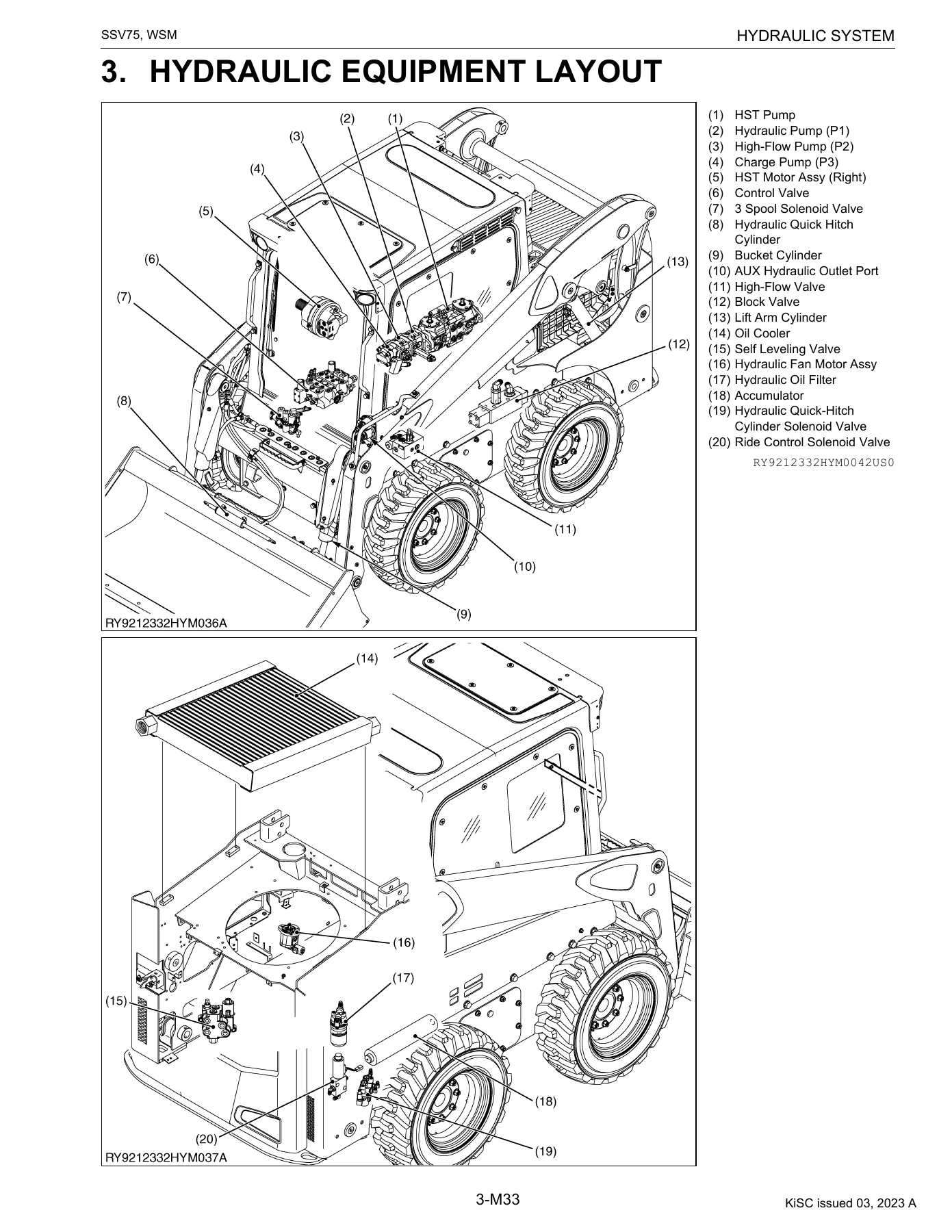
A major part of the Kubota SSV75 Hand and Foot Controls Workshop Manual – 2023 Revision is devoted to the hydraulic system. It includes circuit diagrams for multiple equipment combinations and both principal serial-number groups, plus hydraulic equipment layouts and operating explanations for lift-arm raise, float, bucket dump, self-leveling, AUX single-flow, high-flow operation, ride control, hydraulic hitch, travel, spin turns, charge and flushing circuits, two-speed travel, and parking brake operation. The servicing material then moves into pressure and performance checks, adjustment methods, hydraulic equipment service, and hose routing.
The electrical section is designed for systematic fault finding rather than guesswork. It explains malfunction-diagnosis procedure, circuit testing, connector and harness checks, wiring circuits, electronic-equipment and connector layouts, main-connector terminal names, instrument-panel information, troubleshooting, and user/service-mode setting flow charts. The manual describes using observed symptoms, circuit diagrams, service-mode information, circuit testing, and final operation checks to narrow faults to the affected circuit, sensor, actuator, connector, or harness.
Complete PDF Bookmark Tree
Complete Bookmarks
The complete bookmarks in the “Kubota SSV75 Hand and Foot Controls Workshop Manual – 2023 Revision” are as follows:
+SSV75 HAND AND FOOT CONTROLSp. 1
TO THE READERp. 2
CONTENTSp. 5
+I INFORMATIONp. 6
+INFORMATIONp. 7
1. SAFETY FIRSTp. 8
+2. SAFETY PRECAUTIONS FOR WORKp. 9
[1] PRECAUTIONS BEFORE WORKINGp. 9
[2] PRECAUTIONS WHEN WORKINGp. 10
+3. SAFETY DECALSp. 15
[1] LOCATIONSp. 15
[2] CARE OF LABELSp. 18
4. MAIN SPECIFICATIONSp. 19
5. DIMENSIONSp. 20
+G GENERALp. 21
+GENERALp. 22
+1. ENGINE INDENTIFICATIONp. 23
[1] MODEL NAME AND SERIAL NUMBERp. 23
[2] E4B ENGINEp. 25
[3] CYLINDER NUMBERp. 25
+2. MUFFLER FULL ASSEMBLY IDENTIFICATIONp. 26
[1] PART NUMBER AND SERIAL NUMBERp. 26
3. GENERAL PRECAUTIONSp. 28
+4. HANDLING PRECAUTIONS FOR ELECTRICAL PARTS AND WIRINGp. 32
[1] WIRINGp. 32
[2] FUSESp. 36
[3] CONNECTORp. 36
[4] WASHING THE MACHINE WITH A HIGH-PRESSURE WASHERp. 38
+5. TIGHTENING TORQUESp. 39
[1] GENERAL USE SCREWS, BOLTS AND NUTSp. 39
[2] STUD BOLTSp. 39
+[3] TORQUE FOR HYDRAULIC HOSE FITTINGSp. 40
(1) Torque for Hydraulic Hose Fittingsp. 40
(2) Torques of Lock-Nuts for Elbows with Male Seats and Adapters with O-rings (Straight Threads)p. 41
(3) Torque for Tapering Adaptorsp. 41
[4] HOSE CLAMP SCREW TORQUEp. 42
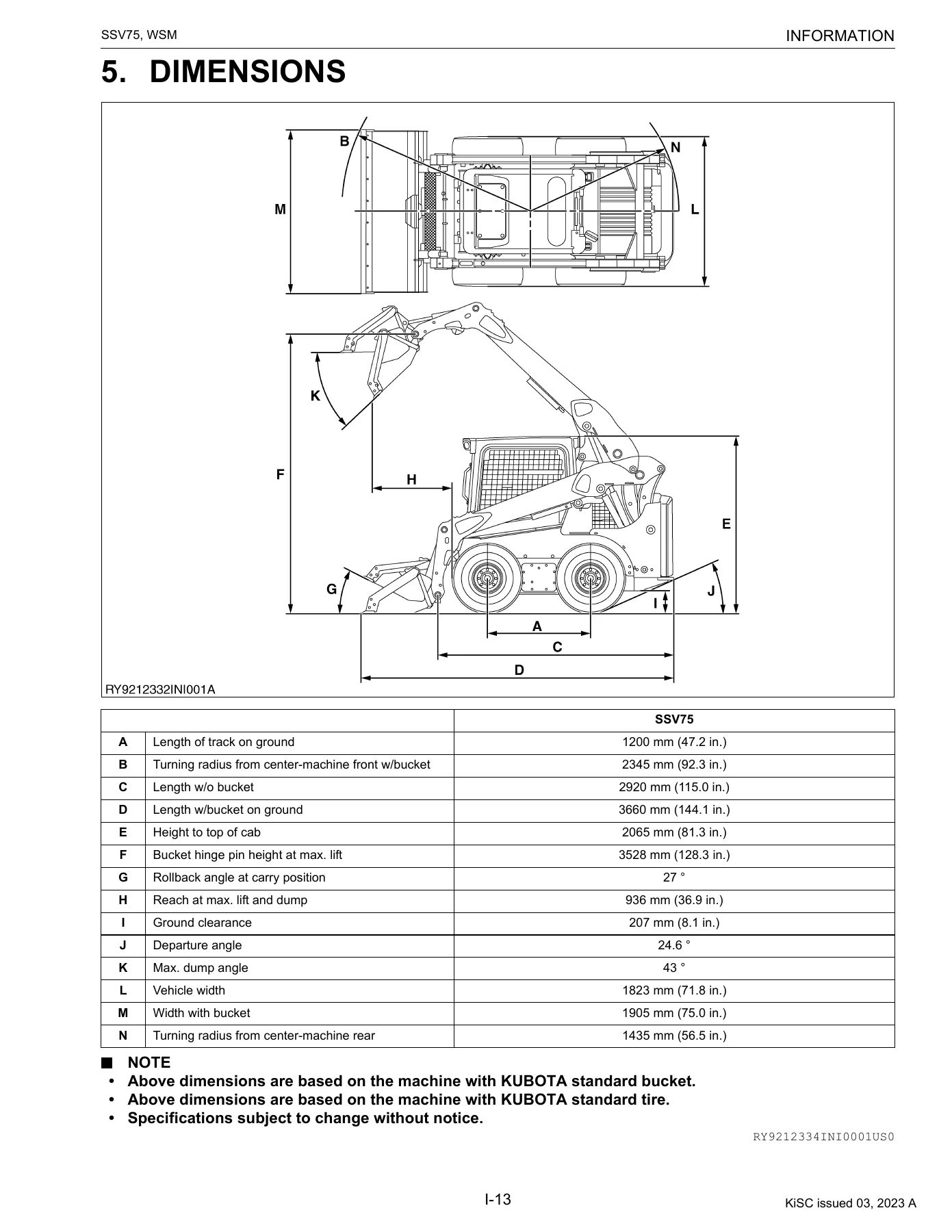
6. LUBRICANTS, FUEL AND COOLANTp. 43
+7. MAINTENANCEp. 44
[1] MAINTENANCE INTERVALSp. 44
+[2] OTHER ADJUSTMENTS AND REPLACEMENTSp. 47
+1 ENGINEp. 51
+GENERALp. 52
1. SPECIFICATIONSp. 53
2. DIMENSIONSp. 54
3. PERFORMANCE CURVEp. 55
+SERVICINGp. 56
+1. ENGINEp. 57
+[1] RADIATORp. 57
(1) Removal and Installationp. 57
+[2] DPF MUFFLERp. 63
(1) Removal and Installationp. 63
+[3] ENGINEp. 68
(1) Removal and Installationp. 68
[4] FUEL HOSE ROUTINGp. 73
+2 MACHINE BODYp. 75
+SERVICINGp. 76
+1. FRONTp. 77
[1] CAB TILTp. 77
[2] LIFT ARM STOPPERp. 79
[3] JACK UPp. 81
[4] DISASSEMBLY AND ASSEMBLY OF LIFT ARM, LINK AND LINK (CONTROL)p. 82
[5] INSTALL THE VACUUM PUMPp. 85
[6] MECHANICAL QUICK HITCHp. 86
+[7] HYDRAULIC QUICK HITCH (OPTION)p. 87
(1) Removal and Installationp. 88
+[8] FRONT PINS AND BUSHESp. 90
+2. UPPER STRUCTUREp. 93
+[1] ROPS (CABIN)p. 93
(1) Removal and Installationp. 93
+[2] WINDSHIELDp. 97
(1) Disassembly/Assemblyp. 97
[3] SEAT BARp. 105
[4] SEAT AND SEATBELTp. 106
+3. LOWER CHASSIS LAYOUTp. 107
+[1] FUEL TANKp. 107
(1) Removal and Installationp. 107
+[2] REAR HOODp. 108
(1) Removal and Installationp. 108
+[3] HYDRAULIC OIL TANKp. 110
(1) Removal and Installationp. 110
+[4] AXLE SHAFTp. 112
(1) Disassembly/Assemblyp. 112
(2) Special Toolsp. 116
+[5] SPROCKETp. 117
(1) Removal and Installationp. 117
+3 HYDRAULIC SYSTEMp. 122
+MECHANISMp. 123
+1. HYDRAULIC CIRCUIT DIAGRAM (SERIAL NO.: TO 12380)p. 124
[1] HYDRAULIC HITCH + HIGH-FLOW + SELF LEVELING VALVE + RIDE CONTROL SPEC.p. 124
[2] MECHANICAL QUICK HITCH SPEC.p. 126
[3] MECHANICAL QUICK HITCH + HIGH-FLOW SPEC.p. 128
[4] MECHANICAL QUICK HITCH + SELF LEVELING VALVE + RIDE CONTROL SPEC.p. 130
[5] MECHANICAL QUICK HITCH + HIGH-FLOW + SELF LEVELING VALVE + RIDE CONTROL SPEC.p. 132
[6] HYDRAULIC HITCH SPEC.p. 134
[7] HYDRAULIC HITCH + HIGH-FLOW SPEC.p. 136
[8] HYDRAULIC HITCH + SELF LEVELING VALVE + RIDE CONTROL SPEC.p. 138
+2. HYDRAULIC CIRCUIT DIAGRAM (SERIAL NO.: FROM 12381)p. 140
[1] HYDRAULIC HITCH + HIGH-FLOW + SELF LEVELING VALVE + RIDE CONTROL SPEC.p. 140
[2] MECHANICAL QUICK HITCH SPEC.p. 142
[3] MECHANICAL QUICK HITCH + HIGH-FLOW SPEC.p. 144
[4] MECHANICAL QUICK HITCH + SELF LEVELING VALVE + RIDE CONTROL SPEC.p. 146
[5] MECHANICAL QUICK HITCH + HIGH-FLOW + SELF LEVELING VALVE + RIDE CONTROL SPEC.p. 148
[6] HYDRAULIC HITCH SPEC.p. 150
[7] HYDRAULIC HITCH + HIGH-FLOW SPEC.p. 152
[8] HYDRAULIC HITCH + SELF LEVELING VALVE + RIDE CONTROL SPEC.p. 154
3. HYDRAULIC EQUIPMENT LAYOUTp. 156
+4. HYDRAULIC SYSTEMp. 157
[1] OVERVIEWp. 157
+[2] FRONT OPERATION SYSTEMp. 158
(1) Overviewp. 158
(2) Flow of Oil when in Neutralp. 159
(3) Raising the Lift Arm Operationp. 160
(4) Lift Arm Float Operationp. 161
(5) Bucket Dump Operationp. 162
(6) Lift Arm Raise + Self-Leveling Switch ON Operation (without Bucket Operation)p. 163
(7) AUX Operation (Single Flow)p. 164
(8) AUX Operation (High-Flow Flow)p. 166
(9) Ride Control Operationp. 168
(10) Hydraulic Hitch Operation (when Locked)p. 169
+[3] TRAVEL SYSTEMp. 170
(1) Functionp. 170
(2) Forward Driving Operationp. 171
(3) Right Turn Operation (Spin Turn)p. 172
(4) Charge Circuitp. 173
(5) Flushing Circuitp. 174
(6) Travel High-Low Operation (Forward Driving)p. 175
(7) Parking Brake Operationp. 176
+SERVICINGp. 177
1. SERVICE DATAp. 179
2. PERFORMANCE CHECKS AND ADJUSTMENT METHODSp. 181
+3. HYDRAULIC EQUIPMENTp. 191
+[1] HST PUMPp. 191
(1) Specificationsp. 191
(2) Componentsp. 192
(3) Joints Arrangementp. 194
(4) Assemblyp. 198
(5) Pump Couplingp. 199
(6) Removal and Installationp. 200
(7) Disassembly/Assemblyp. 202
(8) Special Toolsp. 214
(9) Neutral Adjustmentp. 216
(10) Backup Buzzer Adjustmentp. 217
+[2] GEAR PUMPp. 218
(1) Specificationsp. 218
(2) Componentsp. 218
(3) Joints Arrangementp. 219
+[3] GEAR PUMP (HIGH-FLOW VERSION OPTION)p. 220
(1) Specificationsp. 220
(2) Componentsp. 221
(3) Joints Arrangementp. 222
+[4] CONTROL VALVEp. 223
(1) Specificationsp. 223
(2) Joints Arrangementp. 224
(3) Assemblyp. 225
(4) Removal and Installationp. 228
(5) Disassembly/Assemblyp. 230
+[5] TRAVEL MOTORp. 235
(1) Specificationsp. 235
(2) Componentsp. 236
(3) Joints Arrangementp. 238
(4) Removal and Installationp. 240
(5) Disassembly/Assemblyp. 241
(6) Special Toolsp. 255
+[6] FAN MOTORp. 257
(1) Specificationsp. 257
(2) Componentsp. 258
(3) Joints Arrangementp. 259
(4) Removal and Installationp. 259
(5) Disassembly/Assemblyp. 261
+[7] LIFT ARM CYLINDERp. 265
(1) Specificationsp. 265
(2) Componentsp. 265
(3) Removal and Installationp. 266
(4) Disassembly/Assemblyp. 268
(5) Special Toolsp. 274
+[8] BUCKET CYLINDERp. 278
(1) Specificationsp. 278
(2) Componentsp. 278
(3) Removal and Installationp. 279
+[9] HYDRAULIC QUICK HITCH CYLINDERp. 281
(1) Specificationsp. 281
(2) Componentsp. 281
(3) Removal and Installationp. 282
+[10] 3 SPOOL SOLENOID VALVEp. 283
(1) Specificationsp. 283
(2) Componentsp. 284
(3) Joints Arrangementp. 285
+[11] QUICK HITCH SOLENOID VALVE (OPTION)p. 286
(1) Specificationsp. 286
(2) Componentsp. 287
(3) Joints Arrangementp. 288
+[12] HIGH-FLOW SOLENOID VALVE (OPTION)p. 289
(1) Specificationsp. 289
(2) Joints Arrangementp. 290
(3) Disassembly/Assemblyp. 290
+[13] HORIZONTAL CONTROL VALVE (OPTION)p. 292
(1) Specificationsp. 292
(2) Disassembly/Assemblyp. 293
(3) Joints Arrangementp. 295
+[14] RIDE CONTROL SOLENOID VALVE (OPTION)p. 297
(1) Specificationsp. 297
(2) Componentsp. 298
(3) Accumulator Assemblyp. 299
(4) Joints Arrangementp. 300
+[15] BLOCK VALVE (OPTION)p. 301
(1) Specificationsp. 301
(2) Componentsp. 302
(3) Joints Arrangementp. 303
+4. ROUTING OF HYDRAULIC HOSESp. 304
[1] TYPES OF HYDRAULIC HOSESp. 304
[2] DELIVERY HOSE ROUTINGp. 305
[3] LIFT ARM HOSE ROUTINGp. 307
[4] BUCKET HOSE ROUTINGp. 308
[5] TRAVEL HOSE ROUTINGp. 309
[6] TRAVEL RETURN HOSE ROUTINGp. 310
[7] TRAVEL DRAIN HOSE ROUTINGp. 312
[8] SERVICE PORT HOSE ROUTINGp. 313
[9] HYDRAULIC QUICK HITCH HOSE ROUTINGp. 314
[10] HIGH FLOW HOSE ROUTING (OPTIONAL)p. 315
[11] RIDE CONTROL VALVE HOSE ROUTING (OPTIONAL)p. 316
[12] SUCTION HOSE ROUTINGp. 317
+4 ELECTRICAL SYSTEMp. 318
+SERVICINGp. 319
+1. DIAGNOSING MALFUNCTIONSp. 322
[1] OVERVIEW OF MALFUNCTION DIAGNOSISp. 322
[2] STEPS IN DIAGNOSING MALFUNCTIONSp. 322
[3] TESTING WITH A CIRCUIT TESTERp. 323
+2. WIRING CIRCUITp. 325
[1] PRECAUTIONS ON HOW TO CLAMP THE ELECTRICAL WIRINGp. 325
[2] PRECAUTIONS ON HANDLING ELECTRICAL CONNECTORSp. 325
3. ELECTRONIC EQUIPMENT LAYOUTp. 326
+4. ELECTRICAL CONNECTOR LAYOUTp. 327
[1] ROPS/CAB, A/C SPECIFICATIONp. 327
5. TERMINAL NAMES OF THE MAIN CONNECTORp. 361
+6. INSTRUMENT PANELp. 362
+[1] PANEL FUNCTIONSp. 362
(1) Lamp Displaysp. 362
(2) Warning Lampp. 362
(3) Alarmp. 362
[2] USER MODEp. 363
+[3] SERVICE MODEp. 368
(1) What is the Service Mode?p. 368
(2) Entering the Service Modep. 369
(3) Using the Service Modesp. 371
+7. TROUBLESHOOTINGp. 382
+[1] No.3 HYDRAULIC OIL TEMPERATURE SENSOR ERRORS (E:005)p. 382
(1) Checking via the Panel Displayp. 382
(2) Inspecting each Device Visually and Physicallyp. 382
(3) Testing with a Circuit Testerp. 384
(4) Testing the Equipment Itselfp. 385
+[2] No.4 FUEL SENSOR SYSTEM ERRORS (E:008)p. 386
(1) Checking via the Panel Displayp. 386
(2) Inspecting each Device Visually and Physicallyp. 387
(3) Testing with a Circuit Testerp. 388
(4) Testing the Equipment Itselfp. 389
+[3] No.5 ACCELERATION SYSTEM ERRORS (E:009)p. 390
(1) Checking via the Panel Displayp. 390
(2) Inspecting each Device Visually and Physicallyp. 390
(3) Testing with a Circuit Testerp. 392
(4) Testing the Equipment Itselfp. 394
+[4] No.6 TWO-SPEED TRAVEL SOLENOID ERROR (E:010)p. 395
(1) Checking via the Panel Displayp. 395
(2) Inspecting each Device Visually and Physicallyp. 396
(3) Testing with a Circuit Testerp. 397
(4) Testing the Equipment Itselfp. 398
+[5] No.7 PARKING BRAKE SOLENOID ERRORS (E:011)p. 400
(1) Checking via the Panel Displayp. 400
(2) Inspecting each Device Visually and Physicallyp. 401
(3) Testing with a Circuit Testerp. 403
(4) Testing the Equipment Itselfp. 404
+[6] No.8 HIGH-FLOW SOLENOID ERRORS (E:014)p. 406
(1) Checking via the Panel Displayp. 406
(2) Inspecting each Device Visually and Physicallyp. 408
(3) Testing with a Circuit Testerp. 409
(4) Testing the Equipment Itselfp. 410
+[7] No.9 HYDRAULIC QUICK-HITCH LOCK SOLENOID (E:015)p. 413
(1) Checking via the Panel Displayp. 413
(2) Inspecting each Device Visually and Physicallyp. 414
(3) Testing with a Circuit Testerp. 415
(4) Testing the Equipment Itselfp. 416
+[8] No.10 AUX KNOB ERRORS (E:016)p. 418
(1) Checking via the LCD Panel Displayp. 418
(2) Inspecting each Device Visually and Physicallyp. 419
(3) Testing with a Circuit Testerp. 420
(4) Testing the Equipment Itselfp. 421
+[9] No.11 AUX RIGHT SOLENOID ERRORS (E:018)p. 423
(1) Checking via the LCD Panel Displayp. 423
(2) Inspecting each Device Visually and Physicallyp. 425
(3) Testing with a Circuit Testerp. 426
(4) Testing the Equipment Itselfp. 427
+[10] No.12 AUX LEFT SOLENOID ERRORS (E:019)p. 429
(1) Checking via the LCD Panel Displayp. 429
(2) Inspecting each Device Visually and Physicallyp. 431
(3) Testing with a Circuit Testerp. 432
(4) Testing the Equipment Itselfp. 433
+[11] No.13 5V SHORT SYSTEM ERRORS (E:021)p. 435
(1) Checking via the Panel Displayp. 435
(2) Inspecting each Device Visually and Physicallyp. 436
(3) Testing the Equipment Itselfp. 437
+[12] No.14 OVER VOLTAGE ERRORS (E:023)p. 438
(1) Checking via the Panel Displayp. 438
(2) Testing with a Circuit Testerp. 438
+[13] No.16 CRS COMMUNICATION ERRORS (E:026)p. 439
(1) Checking via the Panel Displayp. 439
(2) Inspecting each Device Visually and Physicallyp. 439
(3) Testing with a Circuit Testerp. 439
(4) Testing the Equipment Itselfp. 440
+[14] No.17 RIDE CONTROL SOLENOID ERRORS (E:027)p. 441
(1) Checking via the Panel Displayp. 441
(2) Inspecting each Device Visually and Physicallyp. 442
(3) Testing with a Circuit Testerp. 444
(4) Testing the Equipment Itselfp. 445
+[15] No.18 FAN SOLENOID ERRORS (E:028)p. 447
(1) Checking via the Panel Displayp. 447
(2) Inspecting each Device Visually and Physicallyp. 447
(3) Testing with a Circuit Testerp. 448
(4) Testing the Equipment Itselfp. 449
+[16] No.19 HYDRAULIC LOCK (LIFT ARM) ERRORS (E:029)p. 450
(1) Checking via the Panel Displayp. 450
(2) Inspecting each Device Visually and Physicallyp. 450
(3) Testing with a Circuit Testerp. 452
(4) Testing the Equipment Itselfp. 452
+[17] No.20 HYDRAULIC LOCK (BUCKET) ERRORS (E:030)p. 454
(1) Checking via the Panel Displayp. 454
(2) Inspecting each Device Visually and Physicallyp. 454
(3) Testing with a Circuit Testerp. 456
(4) Testing the Equipment Itselfp. 456
+[18] No.21 TRAVEL PILOT PRESSURE SENSOR ERRORS (E:031)p. 458
(1) Checking via the Panel Displayp. 458
(2) Inspecting each Device Visually and Physicallyp. 459
(3) Testing with a Circuit Testerp. 460
(4) Testing the Equipment Itselfp. 461
+[19] No.29 WATER TEMPERATURE SENSOR OVERHEATING ERRORS (E:9104)p. 462
(1) Checking via the Panel Displayp. 462
(2) Inspecting each Device Visually and Physicallyp. 463
(3) Testing with a Circuit Testerp. 464
(4) Testing the Equipment Itselfp. 465
+[20] No.47 ENGINE OIL PRESSURE ERRORS (E:9118)p. 466
(1) Checking via the Panel Displayp. 466
(2) Inspecting each Device Visually and Physicallyp. 466
(3) Testing with a Circuit Testerp. 467
(4) Testing the Equipment Itselfp. 469
+[21] No.48 CHARGE ERRORS (E:9119)p. 470
(1) Checking via the Panel Displayp. 470
(2) Inspecting each Device Visually and Physicallyp. 470
(3) Testing with a Circuit Testerp. 471
+[22] No.49 WATER SEPARATOR, WATER FULL ERRORS (E:9120)p. 473
(1) Checking via the Panel Displayp. 473
(2) Inspecting each Device Visually and Physicallyp. 473
8. FLOW CHART OF THE USER MODE AND SERVICE MODE SETTINGSp. 474
+5 CABINp. 476
+MECHANISMp. 477
+1. AIR CONDITIONING SYSTEMp. 478
[1] STRUCTUREp. 478
[2] HOW THE MECHANISMS OF THE SYSTEM WORKp. 480
[3] COMPRESSORp. 481
[4] AIR CONDITIONING UNITp. 484
[5] CONDENSERp. 489
[6] RECEIVERp. 490
[7] PRESSURE SWITCHp. 491
[8] SYSTEM CONTROLSp. 492
[9] ADJUSTING THE AIR FLOW AND DIRECTIONp. 493
+[10] ELECTRICAL SYSTEMp. 494
(1) Electrical Circuitsp. 494
(2) Relaysp. 495
+2. WIPERp. 496
[1] WIPER SWITCHp. 496
[2] WIPER MOTORp. 496
+SERVICINGp. 497
1. TROUBLESHOOTINGp. 498
2. MAINTENANCE AND SERVICE RELATED SPECIFICATIONSp. 501
+3. PRECAUTIONS WHEN REPAIRING THE REFRIGERANT SYSTEMp. 502
+[1] USE OF SERVICE TOOLSp. 502
(1) Manifold Gauge Setp. 502
(2) Refrigerant Charging Hosesp. 504
(3) Vacuum Pump Adapterp. 505
(4) Electric Gas Leak Testerp. 505
(5) Canister Tap Valvep. 505
(6) T-Jointp. 506
(7) R134a Refrigerant Collection/Recycling Devicep. 506
+4. INSPECTING AND CHARGING THE REFRIGERANT SYSTEMp. 507
[1] CHECKING THE SYSTEM WITH A MANIFOLD GAUGEp. 507
+[2] COLLECTION, VACUUMING AND CHARGINGp. 512
(1) Collecting Refrigerantp. 512
(2) Vacuuming Out the Systemp. 513
[3] CHARGING FROM THE HIGH-PRESSURE SIDEp. 514
[4] CHARGING FROM THE LOW-PRESSURE SIDEp. 515
+5. INSPECTION AND DISASSEMBLYp. 516
+[1] CHECKS AND ADJUSTMENTSp. 516
(1) Compressorp. 516
(2) Relaysp. 518
(3) Blower Motorp. 520
(4) Blower Resistorp. 521
(5) A/C Switchp. 521
(6) Fan Switchp. 522
(7) Pressure Switchp. 523
+[2] DISASSEMBLY AND ASSEMBLYp. 525
(1) Removal and Installation of the A/C Unitp. 525
(2) Mounting and Removing the Compressorp. 526
(3) Connecting/Disconnecting A/C Hosesp. 529
(4) Removal and Installation of Heater Hosesp. 532
(5) Heater Hose Routingp. 534
ELECTRICAL CIRCUIT DIAGRAMp. 535
+R REVISED CONTENTSp. 546
+REVISED CONTENTSp. 547
+1. SAFETY DECALSp. 548
[1] LOCATIONSp. 548
[2] CARE OF LABELSp. 553
2. MACHINE INDENTIFICATION (Serial number 50000 to 50438, from 20000 to 24585)p. 554
3. MAINTENANCEp. 556
4. PERFORMANCE CHECKS AND ADJUSTMENT METHODSp. 557
+5. HYDRAULIC CIRCUIT DIAGRAM (SERIAL NO.: TO 12380)p. 558
[1] HYDRAULIC HITCH + HIGH-FLOW + SELF LEVELING VALVE + RIDE CONTROL SPEC.p. 558
[2] MECHANICAL QUICK HITCH SPEC.p. 560
[3] MECHANICAL QUICK HITCH + HIGH-FLOW SPEC.p. 562
[4] MECHANICAL QUICK HITCH + SELF LEVELING VALVE + RIDE CONTROL SPEC.p. 564
[5] MECHANICAL QUICK HITCH + HIGH-FLOW + SELF LEVELING VALVE + RIDE CONTROL SPEC.p. 566
[6] HYDRAULIC HITCH SPEC.p. 568
[7] HYDRAULIC HITCH + HIGH-FLOW SPEC.p. 570
[8] HYDRAULIC HITCH + SELF LEVELING VALVE + RIDE CONTROL SPEC.p. 572
+6. HYDRAULIC CIRCUIT DIAGRAM (SERIAL NO.: FROM 12381)p. 574
[1] HYDRAULIC HITCH + HIGH-FLOW + SELF LEVELING VALVE + RIDE CONTROL SPEC.p. 574
[2] MECHANICAL QUICK HITCH SPEC.p. 576
[3] MECHANICAL QUICK HITCH + HIGH-FLOW SPEC.p. 578
[4] MECHANICAL QUICK HITCH + SELF LEVELING VALVE + RIDE CONTROL SPEC.p. 580
[5] MECHANICAL QUICK HITCH + HIGH-FLOW + SELF LEVELING VALVE + RIDE CONTROL SPEC.p. 582
[6] HYDRAULIC HITCH SPEC.p. 584
[7] HYDRAULIC HITCH + HIGH-FLOW SPEC.p. 586
[8] HYDRAULIC HITCH + SELF LEVELING VALVE + RIDE CONTROL SPEC.p. 588
7. [3] TRAVEL SYSTEMp. 590
8. (2) Inspecting each Device Visually and Physicallyp. 593
9. [1] MAINTENANCE INTERVALSp. 595
10. TERMINAL NAMES OF THE MAIN CONNECTORp. 598
11. Tester Listp. 599
12. ELECTRICAL CIRCUIT DIAGRAMp. 601
13. MAIN SPECIFICATIONSp. 612
14. SPECIFICATIONSp. 613
+15. [3] ENGINEp. 614
(1) Removal and Installationp. 614
16. [4] DISASSEMBLY AND ASSEMBLY OF LIFT ARM, LINK AND LINK (CONTROL)p. 616
+17. [7] HYDRAULIC QUICK HITCH (OPTION)p. 617
(1) Removal and Installationp. 617
+18. [2] REAR HOODp. 618
(1) Removal and Installationp. 618
+19. [9] No.11 AUX RIGHT SOLENOID ERRORS (E:018)p. 619
(1) Checking via the LCD Panel Displayp. 619
(4) Testing the Equipment Itselfp. 620
+20. [10] No.12 AUX LEFT SOLENOID ERRORS (E:019)p. 621
(1) Checking via the LCD Panel Displayp. 621
(4) Testing the Equipment Itselfp. 622
+21. [2] DISASSEMBLY AND ASSEMBLYp. 623
(2) Mounting and Removing the Compressorp. 623
22. LUBRICANTS, FUEL AND COOLANTp. 624
23. [1] MAINTENANCE INTERVALSp. 625
+24. [1] HST PUMPp. 626
(3) Joints Arrangementp. 626
+25. [2] GEAR PUMPp. 630
(3) Joints Arrangementp. 630
+26. [3] GEAR PUMP (HIGH-FLOW VERSION OPTION)p. 631
(3) Joints Arrangementp. 631
+27. [10] 3 SPOOL SOLENOID VALVEp. 632
(3) Joints Arrangementp. 632
28. [6] TRAVEL RETURN HOSE ROUTINGp. 633
Closed-cab service is also covered in depth. Air-conditioning and wiper mechanisms are followed by troubleshooting, maintenance specifications, refrigerant-system precautions, inspection and charging procedures, and component inspection/disassembly. The air-conditioning material includes R134a service precautions, manifold-gauge procedures, evacuation, leak checking, charging methods, and compressor-oil information, providing a practical reference for cab climate-system service.
Chapters Covered
- I INFORMATION
- Safety First
- Safety Precautions for Work
- Safety Decals
- Main Specifications
- Dimensions
- G GENERAL
- Engine Identification
- Muffler Full Assembly Identification
- General Precautions
- Handling Precautions for Electrical Parts and Wiring
- Tightening Torques
- Lubricants, Fuel and Coolant
- Maintenance
- 1 ENGINE
- Specifications
- Dimensions
- Performance Curve
- Engine Servicing
- Radiator Removal and Installation
- DPF Muffler Removal and Installation
- Engine Removal and Installation
- Fuel Hose Routing
- 2 MACHINE BODY
- Front
- Cab Tilt
- Lift Arm Stopper
- Jack Up
- Lift Arm, Link and Control Link Disassembly / Assembly
- Vacuum Pump Installation
- Mechanical Quick Hitch
- Hydraulic Quick Hitch
- Front Pins and Bushes
- Upper Structure / ROPS Cabin
- Windshield
- Seat Bar
- Seat and Seatbelt
- Lower Chassis Layout
- Fuel Tank
- Rear Hood
- Hydraulic Oil Tank
- Axle Shaft
- Sprocket
- 3 HYDRAULIC SYSTEM
- Hydraulic Circuit Diagram – Serial No. To 12380
- Hydraulic Circuit Diagram – Serial No. From 12381
- Hydraulic Equipment Layout
- Hydraulic System
- Service Data
- Performance Checks and Adjustment Methods
- Hydraulic Equipment
- Routing of Hydraulic Hoses
- 4 ELECTRICAL SYSTEM
- Diagnosing Malfunctions
- Wiring Circuit
- Electronic Equipment Layout
- Electrical Connector Layout
- Terminal Names of the Main Connector
- Instrument Panel
- Troubleshooting
- User Mode and Service Mode Settings
- 5 CABIN
- Air Conditioning System
- Wiper
- Troubleshooting
- Maintenance and Service Related Specifications
- Precautions When Repairing the Refrigerant System
- Inspecting and Charging the Refrigerant System
- Inspection and Disassembly
Taken as a whole, the manual gives the technician a connected path from machine identification and scheduled maintenance through system operation, measurement, fault diagnosis, adjustment, and component-level service. It is particularly useful when a repair requires both mechanical procedure and supporting hydraulic or electrical information, because the relevant service data, diagrams, connector information, torque values, and inspection steps are contained within the same SSV75 workshop reference.
Specifications, Fluids and Service Values
Key machine data is included throughout the manual rather than being limited to one summary page. Main specifications cover open- and closed-cab operating weights, engine data, rated operating capacity, tipping load, breakout force, travel speeds, battery information, attachment hydraulic flow and pressure, and fuel capacity. Dimension drawings provide overall machine measurements and working geometry. Engine pages add detailed specifications and a performance curve, while hydraulic service-data pages provide system pressures, travel performance checks, wheel-speed checks, cylinder timing and drift checks, and other adjustment criteria.
Fluid and maintenance information includes engine oil, coolant, fuel, hydraulic oil, chain-case oil, grease, and air-conditioning refrigerant information. The maintenance section separates daily checks from hour-based and time-based service items and includes items for the engine, hydraulic system, drive chain, filters, DPF and emissions-related components, electrical wiring, air cleaner, cooling system, and air conditioner. General torque charts cover screws, bolts, nuts, stud bolts, hydraulic hose fittings, lock-nuts, adaptors, and hose clamps, while individual procedures provide component-specific tightening values where required.
For Repair, Testing and Correct Reassembly
The Kubota SSV75 Hand and Foot Controls Workshop Manual – 2023 Revision supports a wide range of workshop jobs: routine maintenance planning, machine and engine identification, hydraulic pressure and performance checks, electrical fault tracing, circuit interpretation, cab and body disassembly, engine-area service, hydraulic component work, quick-hitch service, axle and sprocket work, air-conditioning diagnosis, and correct reassembly using the stated measurements and tightening values. Following the documented procedures and specifications helps reduce trial-and-error diagnosis and gives the technician the values needed to inspect, adjust, repair, and verify the machine correctly.
Delivery is by instant PDF after purchase, with no physical shipping. Open the manual on a computer, tablet, or phone, keep it available alongside the machine during service, and print the pages you need for workshop use.


Reviews
There are no reviews yet.