Kubota Tractor B2301 B2601 Workshop Manual – PDF DOWNLOAD
Original price was: $86.95.$28.95Current price is: $28.95.
Kubota Tractor B2301 B2601 Workshop Manual – PDF DOWNLOAD
Description
Kubota Tractor B2301 B2601 Workshop Manual – PDF DOWNLOAD
FILE DETAILS:
Kubota Tractor B2301 B2601 Workshop Manual – PDF DOWNLOAD
Language : English
Pages : 341
Downloadable : Yes
File Type : PDF
Size: 8 MB
IMAGES PREVIEW OF THE MANUAL:
DESCRIPTION:
Kubota Tractor B2301 B2601 Workshop Manual – PDF DOWNLOAD
TO THE READER:
This Workshop Manual tells the servicing personnel about the mechanism, servicing and
maintenance of the B2301 and B2601. It contains 4 parts: “Information”, “General”, “Mechanism”
and “Servicing”.
Information
This section primarily contains information below.
• Safety First
• Safety Decal
• Specifications
• Dimensions
General
This section primarily contains information below.
• Engine Identification
• Model Identification
• General Precautions
• Maintenance Check List
• Check and Maintenance
• Special Tools
Mechanism
This section contains information on the structure and the function of the unit. Before you continue
with the subsequent sections, make sure that you read this section.
Refer to the latest version of Workshop Manual (Code No. 9Y021-01870 / 9Y021-18200) for the
diesel engine / tractor mechanism that this workshop manual does not include.
Servicing
This section primarily contains information below.
• Troubleshooting
• Servicing Specifications
• Tightening Torques
• Checking, Disassembling and Servicing
All illustrations, photographs and specifications contained in this manual are of the newest
information available at the time of publication.
KUBOTA reserves the right to change all information at any time without notice.
Since this manual.
The Kubota B2301 and B2601 are two compact tractors that are designed for light to medium-duty tasks such as landscaping, gardening, small-scale farming, and other general property maintenance applications. Both tractors offer a range of features that make them versatile, reliable, and easy to operate. Here’s a closer look at each model:
- Kubota Tractor B2301: The Kubota B2301 is a compact tractor with a 23-horsepower engine and a hydrostatic transmission. It has a Category 1, 3-point hitch that allows it to easily attach and detach implements such as mowers, box scrapers, and tillers. The B2301 is also equipped with power steering, a roll bar, and a seat belt, which make it safe and easy to operate. Additionally, it has a fuel capacity of 6.6 gallons and can achieve a top speed of 13.5 miles per hour.
- Kubota Tractor B2601: The Kubota B2601 is a slightly larger compact tractor with a 26-horsepower engine and a hydrostatic transmission. It has a Category 1, 3-point hitch and a lift capacity of 1,202 pounds, which allows it to easily lift and move heavy implements. The B2601 is also equipped with power steering, a roll bar, and a seat belt, which make it safe and easy to operate. Additionally, it has a fuel capacity of 6.6 gallons and can achieve a top speed of 13.5 miles per hour.
Both the B2301 and B2601 come with a range of features that make them efficient and versatile machines. These features include:
- Hydrostatic transmission for smooth and easy operation
- 4-wheel drive for excellent traction and maneuverability
- ROPS (rollover protective structure) and seat belt for operator safety
- Category 1, 3-point hitch for easy attachment and detachment of implements
- Power steering for easy maneuverability
- Comfortable operator’s station with easy-to-use controls
In addition, both tractors are compatible with a range of Kubota implements, such as mowers, box scrapers, and tillers, which can be attached and detached quickly and easily using the 3-point hitch.
Overall, the Kubota B2301 and B2601 are reliable and efficient compact tractors that are designed to handle a variety of tasks. Whether you need a tractor for landscaping, gardening, or small-scale farming, these models are a great choice for any small to medium-sized job.
TABLE OF CONTENTS:
Kubota Tractor B2301 B2601 Workshop Manual – PDF DOWNLOAD
I INFORMATION 3
1 SAFETY FIRST 5
2 SAFETY DECALS 8
3 SPECIFICATIONS 11
4 TRAVELING SPEEDS 12
G GENERAL 14
1 TRACTOR IDENTIFICATION 16
2 GENERAL PRECAUTIONS 17
3 HANDLING PRECAUTIONS FOR ELECTRICALPARTS AND WIRING 18
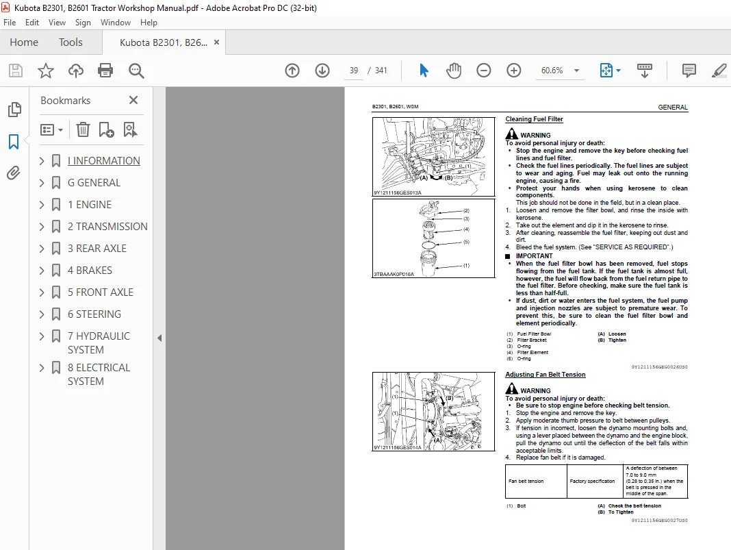
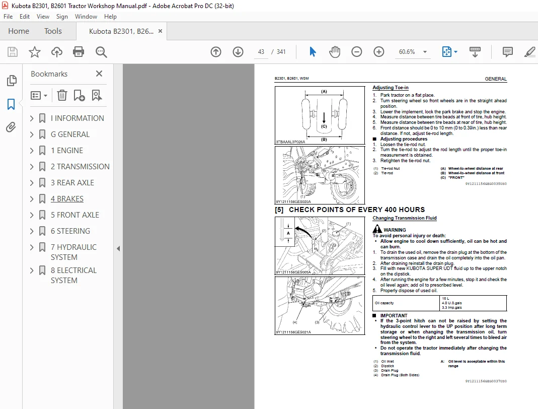
4 LUBRICANTS, FUEL AND COOLANT 23
5 TIGHTENING TORQUES 26
6 MAINTENANCE CHECK LIST 28
7 CHECK AND MAINTENANCE 30
8 SPECIAL TOOLS 50
9 TIRES 60
10 IMPLEMENT LIMITATIONS 67
1 ENGINE 69
MECHANISM 70
1 ENGINE BODY 71
[1] CLOSED BREATHER 71
[2] GOVERNOR 72
SERVICING 74
1 TROUBLESHOOTING 75
2 SERVICING SPECIFICATIONS 79
3 TIGHTENING TORQUES 85
[1] TRACTOR SECTION 85
[2] ENGINE SECTION 85
4 CHECKING, DISASSEMBLING AND SERVICING 86
[1] CHECKING AND ADJUSTING 86
(1) Engine Body 86
(2) Lubricating System 88
(3) Cooling System 88
(4) Fuel System 91
[2] PREPARATION 95
(1) Draining Lubricants and Coolant 95
(2) Separating Engine from Clutch Housing 97
(3) Separating Engine from Front Axle Frame 98
[3] DISASSEMBLING AND ASSEMBLING 99
(1) External Components 99
(2) Cylinder Head and Valve and Oil Pan 99
(3) Gear Case 102
(4) Piston and Connecting Rod 106
(5) Crankshaft 109
[4] SERVICING 111
(1) Cylinder Head and Valves 111
(2) Idle Gear and Camshaft 116
(3) Piston and Connecting Rod 118
(4) Crankshaft 121
(5) Cylinder 125
2 TRANSMISSION 127
MECHANISM 128
1 STRUCTURE 129
2 FRONT CASE 130
3 HYDROSTATIC TRANSMISSION 131
[1] STRUCTURE 131
[2] PUMP AND MOTOR 133
[3] OIL FLOW AND VALVES 134
[4] CONTROL LINKAGE 141
4 SPEED SET DEVICE 142
[1] SPEED SET LINKAGE 142
(1) Speed Set 142
(2) Speed Set Release 143
5 RANGE GEAR SHIFT SECTION 144
6 FRONT WHEEL DRIVE SECTION 145
7 PTO SYSTEM 146
[1] STRUCTURE 146
[2] REAR PTO SECTION 147
[3] REAR PTO / MID-PTO SECTION 148
[4] MID-PTO SECTION 149
[5] INDEPENDENT PTO 150
(1) Hydraulic Circuit 150
(2) Independent PTO Control Valve 150
(3) Independent PTO Clutch 151
(4) Independent PTO Lever “Engaged” 152
(5) Independent PTO Lever “Disengaged” 153
8 DIFFERENTIAL GEAR SYSTEM 154
[1] DIFFERENTIAL FUNCTION 154
[2] DIFFERENTIAL LOCK 155
SERVICING 156
1 TROUBLESHOOTING 157
2 SERVICING SPECIFICATIONS 161
3 TIGHTENING TORQUES 163
4 CHECKING, DISASSEMBLING AND SERVICING 164
[1] CHECKING AND ADJUSTING 164
(1) HST 164
(2) Independent PTO Control Valve 169
[2] PREPARATION 170
(1) Dismounting the Step and Floor Seat 170
[3] DISASSEMBLING AND ASSEMBLING 176
(1) Separating Engine and Clutch Housing 176
(2) Front Case 176
(3) Hydraulic Transmission (HST) 177
(4) PTO Clutch Case 181
(5) Bevel Pinion Shaft 181
(6) Sub Gear Shaft 182
(7) Front Wheel Drive Shaft 183
(8) Independent PTO Clutch Shifter 185
(9) Independent PTO Clutch 186
(10) Mid-PTO Section 190
(11) Differential Gear Section 192
[4] SERVICING 194
(1) HST 194
(2) Independent PTO Clutch 196
(3) Transmission Case 197
(4) Differential Gear 198
3 REAR AXLE 201
MECHANISM 202
1 STRUCTURE 203
SERVICING 204
1 TROUBLESHOOTING 205
2 TIGHTENING TORQUES 206
3 DIASSEMBLING AND SERVICING 207
[1] DIASSEMBLING AND ASSEMBLING 207
(1) Separating Rear Axle Case 207
(2) Disassembling Rear Axle Case 208
[2] SERVICING 209
4 BRAKES 210
MECHANISM 211
1 LINKAGE 212
2 OPERATION 213
SERVICING 214
1 TROUBLESHOOTING 215
2 SERVICING SPECIFICATIONS 216
3 TIGHTENING TORQUES 217
4 CHECKING, DISASSEMBLING AND SERVICING 218
[1] CHECKING AND ADJUSTINGAdjusting 218
[2] DISASSEMBLING AND ASSEMBLING 218
(1) Separating Rear Axle Case 219
(2) Disassembling Rear Axle Case 220
[3] SERVICING 221
5 FRONT AXLE 223
MECHANISM 224
1 STRUCTURE 225
[1] 4 WHEEL DRIVE MODEL 225
SERVICING 226
1 TROUBLESHOOTING 227
2 SERVICING SPECIFICATIONS 228
3 TIGHTENING TORQUES 229
4 CHECKING, DISASSEMBLING AND SERVICING 230
[1] CHECKING AND ADJUSTING 230
[2] DISASSEMBLING AND ASSEMBLING 231
(1) Separating Front Axle Assembly 231
(2) Disassembling Front Axle Assembly 232
[3] SERVICING 238
6 STEERING 242
MECHANISM 243
1 HYDRAULIC CIRCUIT 244
2 STEERING CONTROLLER 245
3 STEERING CYLINDER 246
4 HYDRAULIC PUMP 247
SERVICING 248
1 TROUBLESHOOTING 249
2 SERVICING SPECIFICATIONS 251
3 TIGHTENING TORQUES 252
4 CHECKING, DISASSEMBLING AND SERVICING 253
[1] CHECKING 253
(1) Relief Valve 253
(2) Hydraulic Pump for Power Steering 253
[2] DISASSEMBLING 254
(1) Separating Power Steering Controller 254
(2) Power Steering Controller 254
(3) Power Steering Cylinder 255
[3] SERVICING 257
(1) Power Steering Cylinder 257
7 HYDRAULIC SYSTEM 258
MECHANISM 259
1 HYDRAULIC CIRCUIT 260
2 HYDRAULIC PUMP 261
3 HYDRAULIC CIRCUIT 262
[1] HYDRAULIC CIRCUIT 262
[2] RELIEF VALVE 263
[3] POSITION CONTROL VALVE 264
(1) Structure 264
(2) Operation 265
[4] FEEDBACK LINKAGE FOR POSITION CONTROL 267
4 FRONT LOADER CONTROL VALVE 268
[1] STRUCTURE 268
[2] OPERATION 269
5 REMOTE CONTROL VALVE (IF EQUIPPED) 276
6 HYDRAULIC OUTLET 277
SERVICING 278
1 TROUBLESHOOTING 279
2 SERVICING SPECIFICATIONS 280
3 TIGHTENING TORQUES 281
4 CHECKING, DISASSEMBLING AND SERVICING 282
[1] CHECKING AND ADJUSTING 282
(1) Hydraulic Pump (For 3-Point Hitch Hydraulic System) 282
(2) Hydraulic Pump (For Power Steering, PTO Clutch and HST) 284
(3) 3-Points Hitch Relief Valve 286
(4) Lift Arm 286
[2] DISASSEMBLING AND ASSEMBLING 287
(1) Hydraulic Pump 287
(2) 3-Point Hitch 288
(3) Separating Hydraulic Cylinder From Tractor Body 288
(4) 3-Points Hitch: Hydraulic Cylinder 290
(5) Front Loader Control Valve Assembly (If Equipped) 293
(6) Remote Control Valve (If Equipped) 296
8 ELECTRICAL SYSTEM 298
MECHANISM 299
1 WIRING DIAGRAM 300
2 ENGINE STARTING SYSTEM AND STOPPINGSYSTEM 301
[1] OPC SYSTEM CIRCUIT 301
[2] CONTROLLER 302
[3] SAFETY SWITCH 305
(1) PTO Select Lever Switch 305
(2) PTO Clutch Lever Switch 305
(3) HST Pedal Switch (HST Model) 306
(4) Seat Switch 306
[4] STARTER 307
[5] ENGINE STOP SOLENOID 307
[6] GLOW PLUG 308
3 CHARGING SYSTEM 309
4 LIGHTING SYSTEM 310
[1] HEAD LIGHT 310
[2] TURN SIGNAL LIGHT 310
8-M12[3] HAZARD LIGHT 311
5 INSTRUMENT PANEL 312
[1] EASY CHECKER™ 312
[2] SWITCHES AND SENSORS 312
SERVICING 314
1 TROUBLESHOOTING 315
2 SERVICING SPECIFICATIONS 322
3 TIGHTENING TORQUES 323
4 CHECKING AND ADJUSTING 324
[1] BATTERY 324
[2] FUSE 325
[3] RELAYS 326
(1) Relays 326
[4] STARTING SYSTEM 327
(1) Key Switch 327
(2) Safety Switches 328
(3) OPC Controller 329
(4) Engine Stop Solenoid 329
(5) Starter 329
(6) Glow Plug 330
[5] CHARGING SYSTEM 331
(1) AC Dynamo 331
(2) Regulator 331
[6] LIGHTING SYSTEM 332
(1) Combination Switch 332
(2) Flasher Unit 334
[7] WARNING LAMP, INDICATOR LAMP AND GAUGE 334
(1) Instrument Panel 334
(2) Engine Oil Pressure Switch 335
(3) Coolant Temperature Sensor 335
(4) Fuel Sensor 336
5 DISASSEMBLING AND ASSEMBLING 337
[1] STARTER 337
[2] AC DYNAMO 338
6 SERVICING 339
[1] STARTER 339
Contact us: [email protected]
PLEASE NOTE:
- This is the SAME manual used by the dealers to troubleshoot any faults in your vehicle. This can be yours in 2 minutes after the payment is made.
- Contact us at [email protected] should you have any queries before your purchase or that you need any other service / repair / parts operators manual.
S.V