
Kubota U20-3 U25-3 Excavator Workshop Manual PDF – Complete WSM
Original price was: $39.95.$24.95Current price is: $24.95.
Complete Kubota U20-3 and U25-3 excavator Workshop Manual (WSM) in PDF. Covers General, Machine Body, D1105 engine, hydraulic system, electrical system, service data and full disassembly/reassembly procedures.
Description
Kubota U20-3 U25-3 Excavator Workshop Manual PDF
This is the complete Workshop Manual (WSM) for the Kubota U20-3 and U25-3 compact excavators. It is the same technical document a workshop uses to service, diagnose, disassemble and reassemble these machines from top to bottom. Everything is broken into five top-level divisions — General, Machine body, Engine, Hydraulic System and Electrical System — and each one is split into a Mechanism section (how it works) and a Service section (how to test, repair and rebuild it).
The manual covers the canopy and cabin configurations, rubber and iron crawler variants, and the fixed and retractable undercarriage on the U20-3. The U25-3 runs the D1105-EBH-11 engine while the U20-3 uses the D1105-EBH-10, both covered in detail in the Engine division.
File Details
- Manual type: Workshop Manual (WSM)
- Brand: Kubota
- Models: U20-3, U25-3 (canopy and cabin)
- Engines: Kubota D1105-EBH-10 (U20-3), D1105-EBH-11 (U25-3)
- Language: English
- File format: PDF
- Document number: 97899-60740
- Publication date: Printed in Japan 0308
- Page count: Approx. 508 pages
Chapters Covered
- I. General
- Body and engine identification marks
- Safety precautions for servicing, disassembly and reassembly
- Important safety process and critical functional process
- Important inspection items after reassembling
- Servicing fundamentals — O-rings, oil seals, circlips, roll pins, piping
- Machine quality specifications
- Maintenance intervals chart
- Periodic replacement of important parts
- II. Machine Body — Mechanism Section
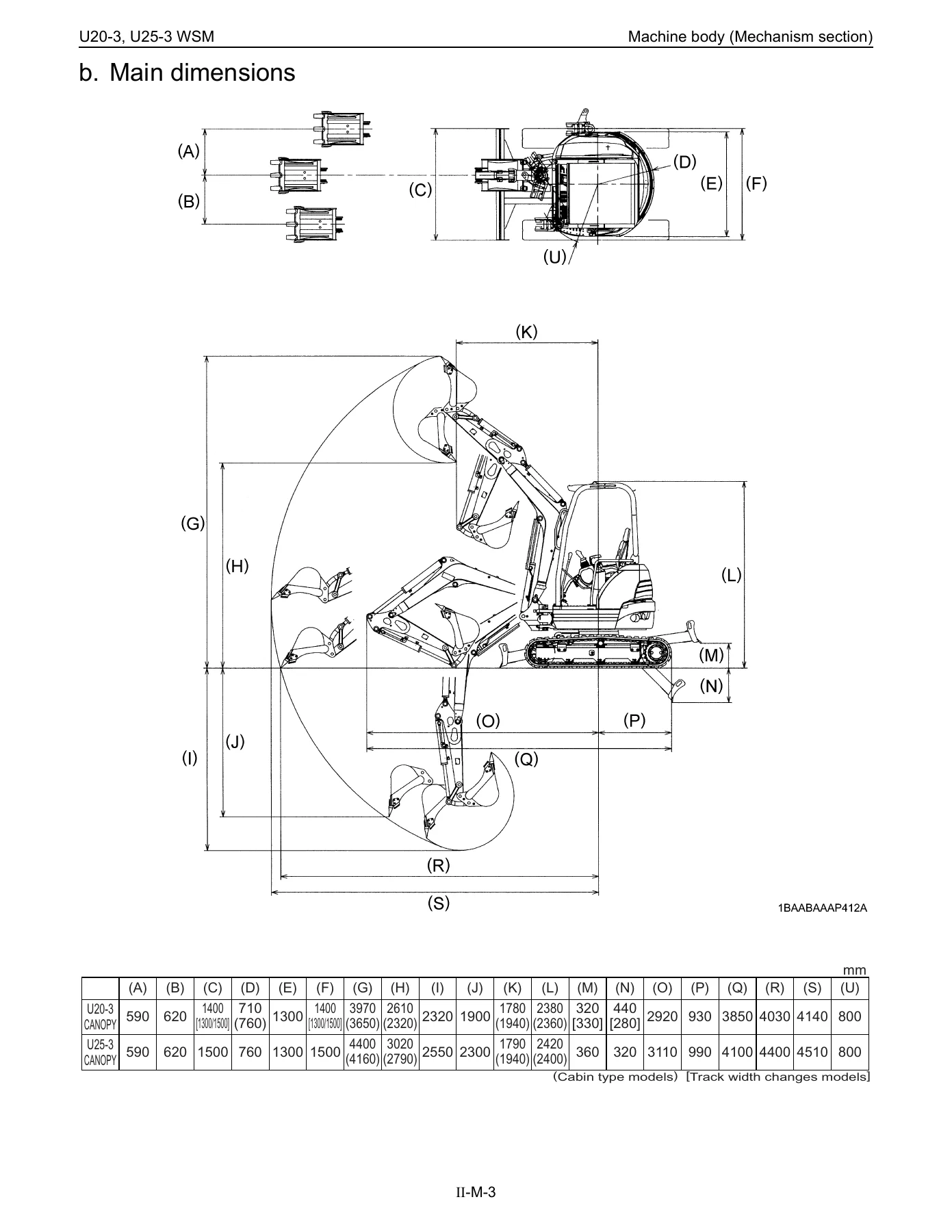
- Specifications and main dimensions
- Components interchangeability (bucket)
- Control linkage
- Engine mount
- Undercarriage
- II. Machine Body — Service Section
- Machine weight, specifications, lever stroke and operating force
- Dimensions of parts
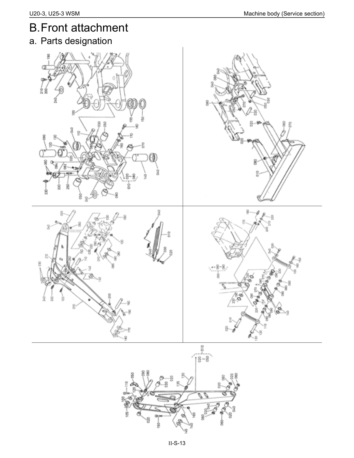
- Front attachment — parts designation, bucket exchange, bucket teeth and side cutters
- Dust seal and thrust collar installation, pin and bush installation
- Front hose
- Upper structure — levers, pedals, hydraulic oil tank, fuel tank, counterweight
- Cab / canopy installation
- Under carriage — swivel bearing, grease tube, track tension device, rollers, crawler replacement
- III. Engine (05-M Series) — Mechanism Section
- Engine features and body
- Cylinder block, cylinder head, crankshaft
- Piston and piston rings, connecting rod
- Rocker arm, camshaft, fuel camshaft, flywheel
- Lubricating system — oil pump, relief valve, oil filter cartridge, oil pressure switch
- Cooling system — water pump, thermostat, radiator, radiator cap
- Intake / exhaust system — air cleaner, muffler
- Fuel system — injection pump, injection nozzle, fuel filter, governor, automatic advance timer
- Electrical system — charging system
- Turbo charger system
- III. Engine — Service Section
- Engine identification and general precautions
- Tightening torques
- Troubleshooting
- Servicing specifications
- Maintenance check list
- Check and maintenance procedures
- Engine body — checking and adjusting, disassembling and assembling
- Cylinder head, gear case, piston and connecting rod, flywheel and crankshaft
- Lubricating system, cooling system, fuel system
- Electrical system — starter, alternator, glow plug
- Turbo charger system
- IV. Hydraulic System — Mechanism Section
- Features and specifications of the hydraulic system
- Main pump — structure, performance curve, operating principle
- Control valve — specifications, sectional view, arm regeneration, boom anti-fall valve, straight travel circuit, relief valve
- Pilot valve — structure, control diagram, functions
- Swivel motor — structure, operating principle, negative brake
- Rotary joint (swivel joint)
- Travel motor — Fujikoshi (U20-3) and Kayaba (U25-3)
- Counter balance valve, Hi-Lo change, reduction gear, anti-cavitation valve
- Hydraulic circuit diagrams
- Hydraulic components layout
- IV. Hydraulic System — Service Section
- Troubleshooting — common circuit, hydraulics, pump, motor, swivel, traveling
- Specifications — pump, relief valve, swivel, traveling, cylinder
- Testing — pump flow, pressure measurement, drain measurement, block performance, operating speed
- Disassembling and assembling — pump, control valve, pilot valve, swivel motor, rotary joint, traveling motor
- Cylinder and hydraulic hose service
- Other hydraulic valves — selector valve, pilot filter, accumulator, third line
- V. Electrical System — Mechanism Section
- Components and harness layout
- Battery circuit
- Safety relay circuit (automatic release function)
- Auto glow circuit
- Fuel control circuit and engine stop solenoid
- Engine oil pressure sensor circuit
- Horn circuit
- Cab and working lamp circuit
- Meter panel, heater circuit, travel hi-speed control circuit
- V. Electrical System — Service Section
- Wire harness installation — front, engine, swivel frame, around seat
- Troubleshooting — engine, meter panel, others
- Check instructions
What makes this WSM stand apart from a generic repair guide is the way it is structured. Every subsystem has a Mechanism chapter that explains how the component is built and how it behaves, and a matching Service chapter that walks through measurement, adjustment, disassembly, inspection and reassembly with factory specification values and allowable limits printed alongside. For the hydraulic system in particular, there are operating-principle sections covering arm regeneration, boom anti-fall valve logic, straight travel circuit activation, negative brake release and counter balance valve behaviour, all of which a technician needs to understand before cracking open the control valve.
What This Manual Enables You to Do
With this manual on hand you can carry out routine service and full repairs on both excavators without guesswork. The General division lays out maintenance intervals and the periodic replacement schedule for the fuel and hydraulic hoses, alongside the correct service procedures for O-rings, oil seals and circlips. The Machine Body division covers everything from bucket change and bucket teeth replacement through to track tension adjustment, track roller replacement and full undercarriage work, including the variable-track U20-3.
IMAGES PREVIEW
The Engine division is deep enough to guide a top-end overhaul on the D1105 — cylinder head disassembly and valve service, piston and connecting rod work, crankshaft and bearing clearance checks, injection pump and nozzle servicing, governor and automatic advance timer operation, starter and alternator repair, and glow plug testing. The Hydraulic System division supports pump overhaul, control valve and pilot valve rebuild, swivel motor and travel motor disassembly with correct Hi-Lo change and anti-cavitation behaviour, rotary joint service, cylinder resealing, and pressure testing with factory targets. The Electrical System division maps the whole harness, covers every circuit from the auto glow timer to the meter panel and horn, and includes the diagnostic steps used to trace faults.
Why Correct Specifications Matter
Compact excavators are unforgiving of wrong clearances, wrong torques and wrong assembly order. A boom anti-fall valve set up incorrectly can drop the boom under load; a pilot valve rebuilt without the correct spring washer orientation can leave the machine drifting; a travel motor reassembled with the valve plate misaligned will run in the wrong direction. This WSM puts the tightening torques, servicing limits and assembly sequence in front of you so the repair is done right the first time.
Instant PDF Delivery
The manual is delivered as an instant-download PDF after checkout — no shipping, no waiting, no physical media. Read it on a laptop, tablet or phone at the machine, or print the pages you need for the bench. Because it is a searchable-text PDF you can jump straight to the torque table, the hydraulic schematic or the fault-diagnosis page you need mid-job.
Reviews
There are no reviews yet.