Kyocera KM-3050 KM-4050 KM-5050 Service Manual – Full Repair Guide PDF
Original price was: $95.00.$15.95Current price is: $15.95.
Official Kyocera Mita KM-3050, KM-4050, and KM-5050 service manual covering full specifications, installation, maintenance mode, troubleshooting, paper misfeed/self-diagnostic codes, image formation problems, complete assembly/disassembly procedures, electrical parts layout, PWB operation, and mechanical theory. 252 pages of factory service data — instant PDF download. Part No. 2GN70760.
Description
Kyocera KM-3050 KM-4050 KM-5050 Service Manual – Full Repair Guide PDF DOWNLOAD
DESCRIPTION
Kyocera Mita KM-3050 / KM-4050 / KM-5050 Official Service Manual (PDF)
This is the official Kyocera Mita factory service manual for the KM-3050, KM-4050, and KM-5050 monochrome digital multifunctional systems — published July 2006 under part number 2GN70760. This is the exact technical reference used by Kyocera-trained service engineers for all disassembly, reassembly, adjustment, troubleshooting, and maintenance of these 30 ppm, 40 ppm, and 50 ppm office copier/printer/scanner systems.
Whether you’re a copier technician diagnosing a Kyocera KM-4050 paper misfeed, an independent service engineer performing a KM-5050 drum unit or fuser replacement, or a workshop engineer chasing a self-diagnostic fault code, this Kyocera KM-3050 KM-4050 KM-5050 service manual PDF delivers factory-level procedures the moment you download it.
📋 File Details
| Detail | Info |
|---|---|
| Manual Title | KM-3050 / KM-4050 / KM-5050 Service Manual |
| Part Number | 2GN70760 |
| Models Covered | Kyocera Mita KM-3050 (30 ppm), KM-4050 (40 ppm), KM-5050 (50 ppm) |
| Year | July 2006 (First Edition) |
| Language | English |
| Pages | 252 Pages |
| PDF Quality | Original factory digital file — clean, US Letter format, fully readable |
| File Size | ~2.8 MB |
Table of Contents
Section 1-1 — Specifications
- Full Machine Specifications
- Parts names (machine & operation panel)
- Machine cross-section diagrams
Section 1-2 — Installation
- Installation environment requirements
- Unpacking and installation procedure
- Setting initial copy modes
- Installing the key counter (optional)
Section 1-3 — Maintenance Mode
- Executing a maintenance mode item
- Maintenance mode item list (full list of service codes)
- Contents and detail of all maintenance mode items
Section 1-4 — Troubleshooting
- Paper Misfeed Detection:
- Paper misfeed indication methods
- Paper misfeed detection conditions (full location matrix)
- Paper misfeed clearing procedures
- Self-Diagnosis:
- Self-diagnostic function
- Complete self-diagnostic code list (all fault codes with descriptions)
- Image Formation Problems (19 fault conditions):
- No image (entirely white)
- No image (entirely black)
- Image too light
- Background visible
- White line longitudinal
- Black line longitudinal
- Black line lateral
- One side of copy darker than the other
- Black dots on image
- Image blurred
- Leading edge consistently misaligned
- Leading edge sporadically misaligned
- Paper creases
- Offset occurs
- Image partly missing
- Poor fusing
- Image out of focus
- Image centre not aligned with original
- Image not square
- Electrical Problems — systematic fault-finding for all electrical faults
- Mechanical Problems — systematic fault-finding for mechanical faults
Section 1-5 — Assembly and Disassembly
- Precautions for assembly and disassembly (drum, toner handling)
- Paper Feed Section:
- Detaching and refitting forwarding, paper feed, and separation pulleys
- Detaching and refitting MP separation, MP paper feed, and MP forwarding pulleys
- Detaching and refitting left and right registration cleaners
- Optical Section:
- Detaching and refitting the exposure lamp
- Detaching and refitting scanner wires
- Detaching and refitting the ISU (reference)
- Adjusting ISU position (reference)
- Detaching and refitting the laser scanner unit
- Adjusting laser scanner unit skew (reference)
- Drum Section:
- Detaching and refitting the drum unit
- Detaching and refitting the main charger unit
- Developing Section:
- Detaching and refitting the developing unit
- Transfer Section:
- Detaching and refitting the transfer roller unit
- Fuser Section:
- Detaching and refitting the fuser unit
- Detaching and refitting heat roller separation claws
- Detaching and refitting the press roller
- Detaching and refitting the fuser heater
- Detaching and refitting the heat roller
- Detaching and refitting fuser thermistors 1 and 2
- Adjusting front position of fuser unit (lateral squareness)
- Others:
- Detaching and refitting ozone filters 1 and 2
- Detaching and refitting dust filters 1 and 2
Section 1-6 — Requirements on PWB Replacement
- Upgrading the firmware
- Adjustment-free variable resistors (VR)
- Remarks on main PWB replacement
- Remarks on scanner PWB replacement
Section 2-1 — Mechanical Construction (Theory of Operation)
- Paper Feed Section — mechanical feed theory
- Main Charging Section — single positive corona charging
- Optical Section:
- Original scanning theory
- Image printing theory (laser path and exposure)
- Developing Section:
- Single component developing system theory
- Transfer and Separation Sections
- Cleaning and Charge Erasing Sections
- Fuser Section — heat roller, halogen heaters, thermostat protection
- Eject and Switchback Sections
- Duplex Section — paper conveying operation in duplex copying
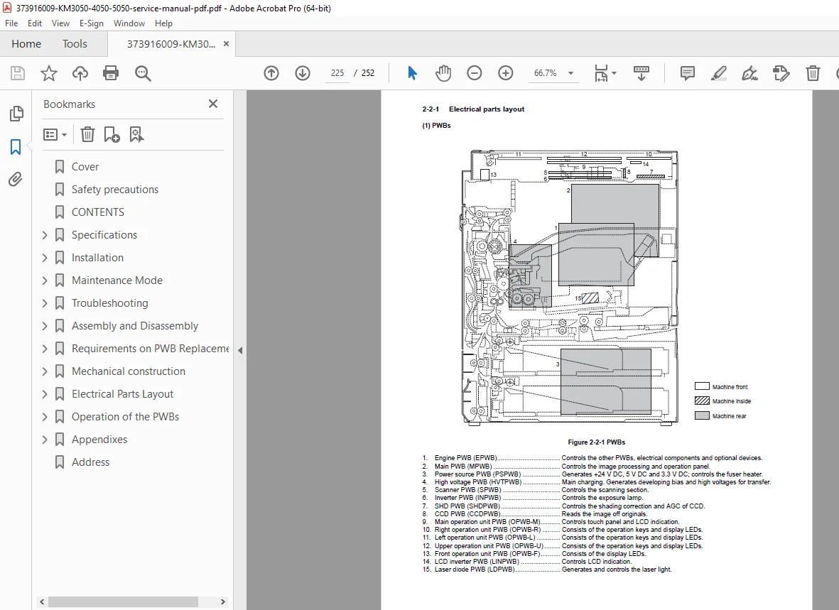
Section 2-2 — Electrical Parts Layout
- PCBs / PWBs layout diagram
- Switches and sensors layout
- Motors layout
- Other electrical components layout
Section 2-3 — Operation of the PWBs
- Power Source PWB — detailed operation
- Engine PWB — detailed operation
Section 2-4 — Appendixes
- Maintenance parts list
- Periodic maintenance procedures
- Chart of image adjustment procedures
- General wiring diagram
⚙️ Key Technical Specifications at a Glance
| Specification | KM-3050 | KM-4050 | KM-5050 |
|---|---|---|---|
| Copy Speed (A4/Letter) | 30 ppm | 40 ppm | 50 ppm |
| Copy Speed (A3/Ledger) | 20 ppm | 23 ppm | 26 ppm |
| First Copy Time | 3.9 s | 3.5 s | 3.5 s |
| Warm-Up Time | 30 s | 30 s | 30 s |
| Resolution (Copy/Print) | 600 × 600 dpi | 600 × 600 dpi | 600 × 600 dpi |
| Print Resolution | Fast 1200 / 600 / 300 dpi | Fast 1200 / 600 / 300 dpi | Fast 1200 / 600 / 300 dpi |
| Photoconductor | a-Si drum (40 mm dia.) | a-Si drum (40 mm dia.) | a-Si drum (40 mm dia.) |
| Charging System | Single positive corona | Single positive corona | Single positive corona |
| Developing | Dry reverse, 1-component magnetic toner | Same | Same |
| Transfer | Transfer roller | Transfer roller | Transfer roller |
| Fusing | Heat roller, halogen heaters | Same | Same |
| Cassette Capacity | 500 sheets (80 g/m²) | Same | Same |
| MP Tray Capacity | 200 sheets (80 g/m²) | Same | Same |
| Output Tray | 250 sheets | Same | Same |
| Multiple Copying | 1–999 sheets | Same | Same |
| Standard Memory | 512 MB | 512 MB | 512 MB |
| Max Memory | 1,024 MB | 1,024 MB | 1,024 MB |
| Hard Disk | 40 GB | 40 GB | 40 GB |
| Scanner Speed (Mono) | 50 sheets/min (1-sided) | Same | Same |
| Scanner Speed (Colour) | 25 sheets/min (1-sided) | Same | Same |
| Network | 10Base-T / 100Base-TX | Same | Same |
| Emulations | PCL6, KPDL3, KC-GL, Line Printer, IBM Proprinter X24E, EPSON LQ-850, DIABLO 630 | Same | Same |
| Dimensions (W×D×H) | 599 × 646 × 745 mm | Same | Same |
| Weight | Approx. 85 kg | Same | Same |
| Power (120V) | 120 V AC, 60 Hz, 11.5 A | Same | Same |
🔧 Who Needs This Manual?
- ✅ Copier technicians performing a Kyocera KM-3050 / KM-4050 / KM-5050 PM service or overhaul
- ✅ Engineers troubleshooting Kyocera KM-5050 self-diagnostic error codes or paper misfeed faults
- ✅ Service centres replacing fuser unit, drum unit, transfer roller, or developer unit on any of the three models
- ✅ Workshops performing laser scanner unit skew adjustment or ISU alignment
- ✅ Biomedical / office equipment engineers who need the complete Kyocera KM-3050 KM-4050 wiring diagram and PWB layout
- ✅ Anyone needing a Kyocera KM-3050 KM-4050 KM-5050 service manual PDF without delay
Every jam code, misfeed condition, and disassembly step for the KM-3050, KM-4050, and KM-5050 — all in one download. Stop guessing and start fixing with the exact factory procedures used by Kyocera service engineers. Purchase now and have your manual ready before your next service call.