
Laverda 3700 & 3700R Combine Harvester Parts Manual – PDF Spare Parts Catalogue
Original price was: $39.95.$24.95Current price is: $24.95.
Illustrated spare parts catalogue for the Laverda 3700 and 3700R combine harvesters, covering engine, transmission, hydraulics, electrics, threshing and undercarriage assemblies with order numbers, quantities and modification data.
Description
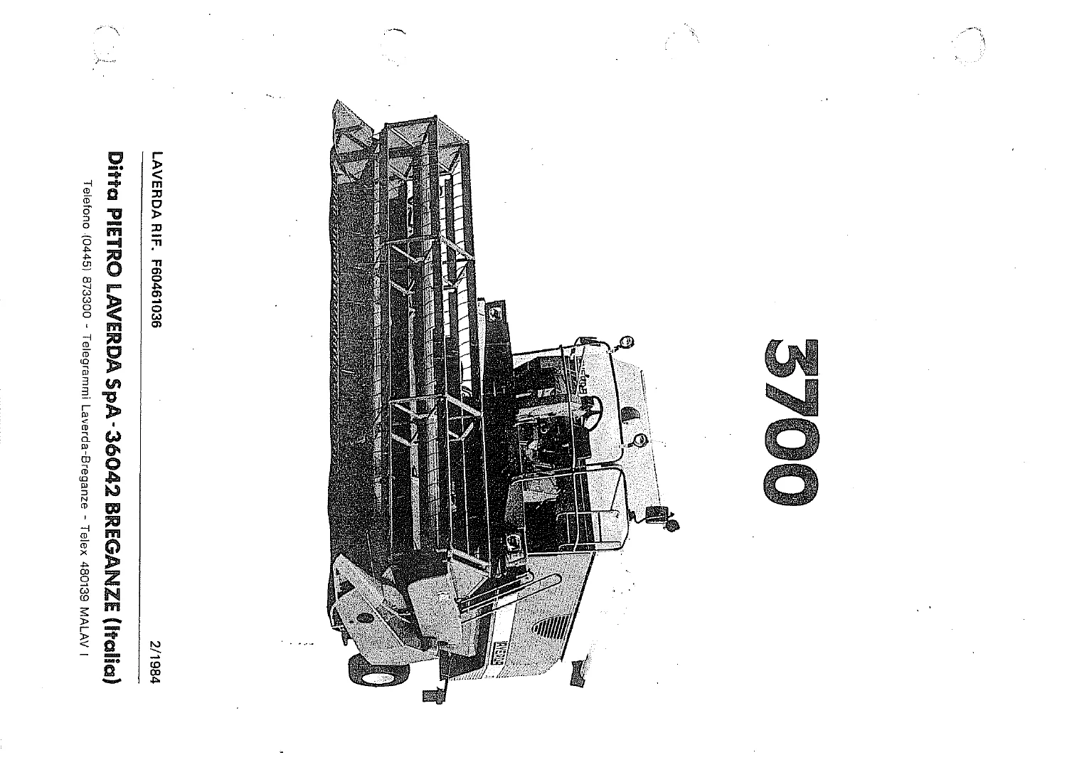
The Laverda 3700 and 3700R Combine Harvester Parts Manual is the illustrated spare parts catalogue issued for the Laverda 3700 and 3700R self-propelled combine harvesters by Ditta Pietro Laverda S.p.A. of Breganze, Italy. It is not a repair guide in the usual sense – it is the document the parts counter and the workshop reach for when a component has to be identified, matched and ordered correctly the first time.
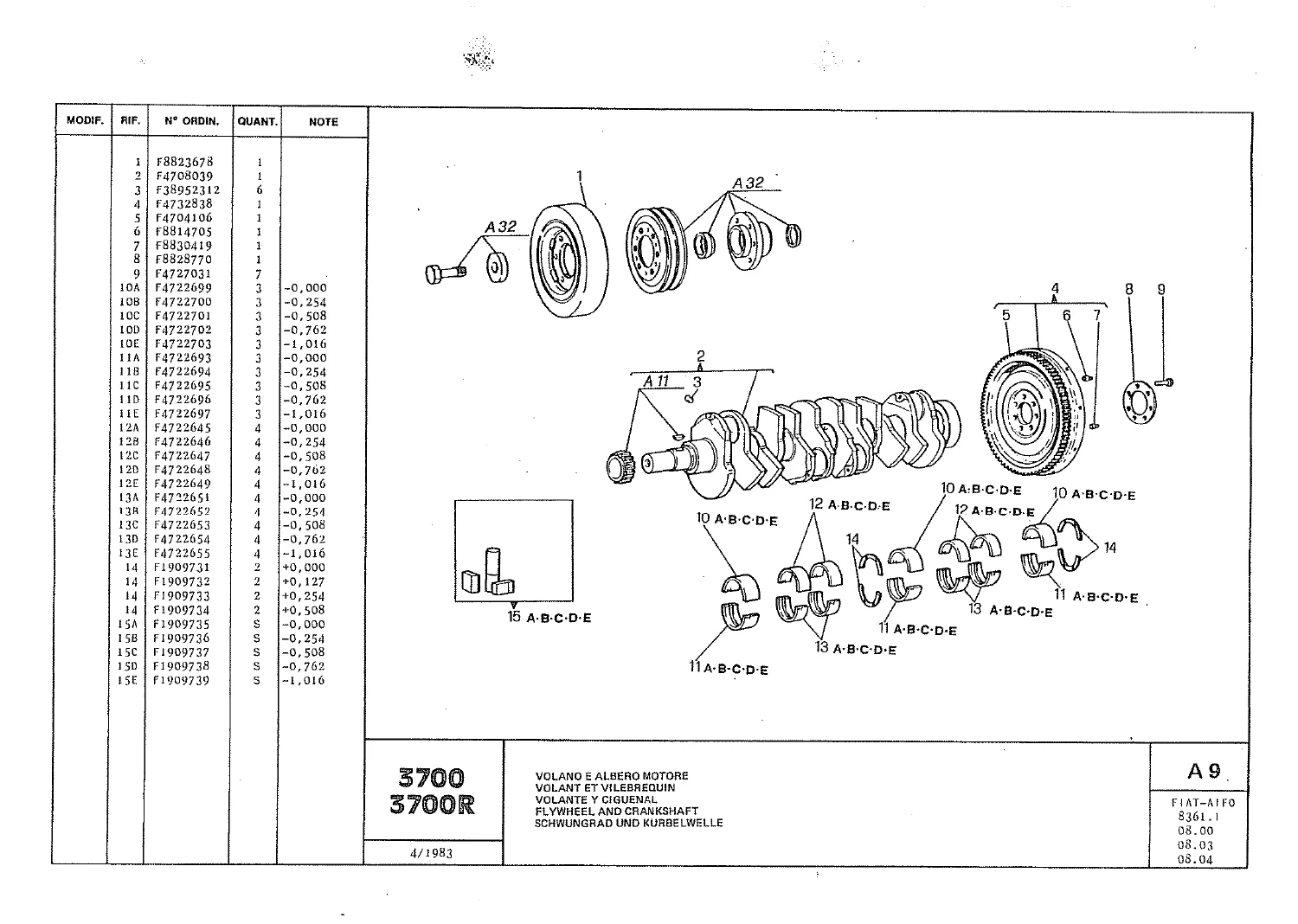
Every assembly is drawn as an exploded illustration with numbered callouts, and each callout is tied to a part number, a quantity and, where relevant, a modification reference. That combination is what makes the Laverda 3700 and 3700R Combine Harvester Parts Manual useful long after the machine has left the dealer yard: it tells you not only what a part is, but which version of it belongs on your particular machine.
File Details
- Manual type: Illustrated spare parts catalogue (parts manual)
- Brand: Laverda – Ditta Pietro Laverda S.p.A., 36042 Breganze, Italy
- Models covered: Laverda 3700, Laverda 3700R combine harvesters
- Engine referenced: FIAT-AIFO 8361.1
- Languages: Italian, French, Spanish, English and German running simultaneously in the tables and captions
- Page count: 626 pages
- File format: PDF
- Dates shown in the document: 4/1983, 2/1984, 7/1984
- Ordering information required: machine type, chassis number, engine type and number, part order number and quantity
Chapters Covered
The catalogue is divided into lettered and numbered tables, each one a separate sub-assembly with its own illustration and parts list. The main groups are:
- A1 Basamento – cylinder block
- A2 Coppa olio – oil sump
- A3 / A4 Coperchi right and left hand – engine covers
- A5 Sfiatatoio ed aerazione motore – engine breather and ventilation
- A6 Testate e cilindri – cylinder heads and cylinders
- A7 Condotto di aspirazione – intake manifold
- A8 Condotto di scarico – exhaust manifold
- A9 Volano e albero motore – flywheel and crankshaft
- A10 Bielle e stantuffi – connecting rods and pistons
- A11 Distribuzione – timing
- A12 Valvole e bilancieri – valves and rocker arms
- A13 Pompa iniezione – injection pump
- A14 Organi di trascinamento e variatore d’anticipo – drive gears and advance variator
- A15 Variatore di anticipo – advance variator
- A16 Tubazioni e iniettori – pipes and injectors
- A17A / A17B Elementi pompa iniezione – injection pump elements
- A18A / A18B / A18C Elementi regolatore di velocita – speed governor elements
- A19 Pompa alimentazione – fuel lift pump
- A20 Polverizzatore – nozzle
- A21 Tubazioni da pompa a filtri – pump to filter lines
- A22 Filtro combustibile – fuel filter
- A23 Pompa di mandata e comando – delivery pump and drive
- A24A / A24B Tubazioni e indicatori – lines and indicators
- A25 Scambiatore di calore – heat exchanger
- A26 Pompa acqua e comandi – water pump and drives
- A27 Tubazioni – water piping
- A28 / A28.1 Ventilatore e comando – fan and drive, including the hydrostatic fan variant
- A29 Alternatore e motorino d’avviamento – alternator and starter motor
- A30 Elementi alternatore – alternator components
- A31 Elementi motorino d’avviamento – starter motor components
- A50 Motore – complete engine listing
- A51 / A51A Aspirazione – air intake and filter
- A52 Scarico – exhaust system
- A53 Serbatoio combustibile – fuel tank
- A54 Filtro gasolio – fuel oil filter
- A55 Scarico olio – oil drain
- A56 Filtro radiatore – rotary radiator screen
- A57 Trasmissione filtro radiatore – screen drive
- A58A / A58B / A58B1 Radiatori – radiators and radiator elements
- A59 Tubazioni radiatore e supporti motore – radiator pipes and engine mounts
- A60 Albero presa di forza – power take-off shaft
- B1A1 Variatore, mechanical transmission
- B1A2 Telaio variatore – variator frame
- B1A3 / B1A3.1 Frizione e cambio – clutch and gearbox, plus clutch elements
- B1A4 / B1A5 / B1A6 Elementi cambio, ingranaggi, differenziale – gearbox housing, gear elements and differential
- B1B1 / B1B2 Trasmissione e telaio pompa – hydrostatic pump drive and frame
- B1B3 / B1B4 / B1B5 / B1B6 Cambio hydrostatic transmission – housing, gear elements and differential
- B2 / B3 Freni – brakes, including Brembo and Stilmec element kits
- B4A / B4B Semiassi – half shafts, wheel and crawler versions
- B5 / B6 Riduttori and elements – final drives and their components
- B7A1 Pneumatici anteriori – front tyres
- B7B1 Ruota motrice cingolatura – crawler drive wheel
- B7B2 Carrello cingolo – track carriage
- B7B3 Catenaria – track chain
- B7B4 Elementi rulli e ruote tendicingolo – rollers and idler wheels
- B8 Supporto assale posteriore – rear axle support
- B9 Assale posteriore – rear axle
- B10 Pneumatici posteriori – rear tyres
- C1 Trasmissione – belt transmission
- C2A1 Cassa – housing
- C2A3 Comando piattaforma – cutting table drive
- C2A4 Albero superiore – upper shaft
- C2A5 Rullo inferiore alimentatore – bottom feed roller
- D1 Telaio – chassis and frame
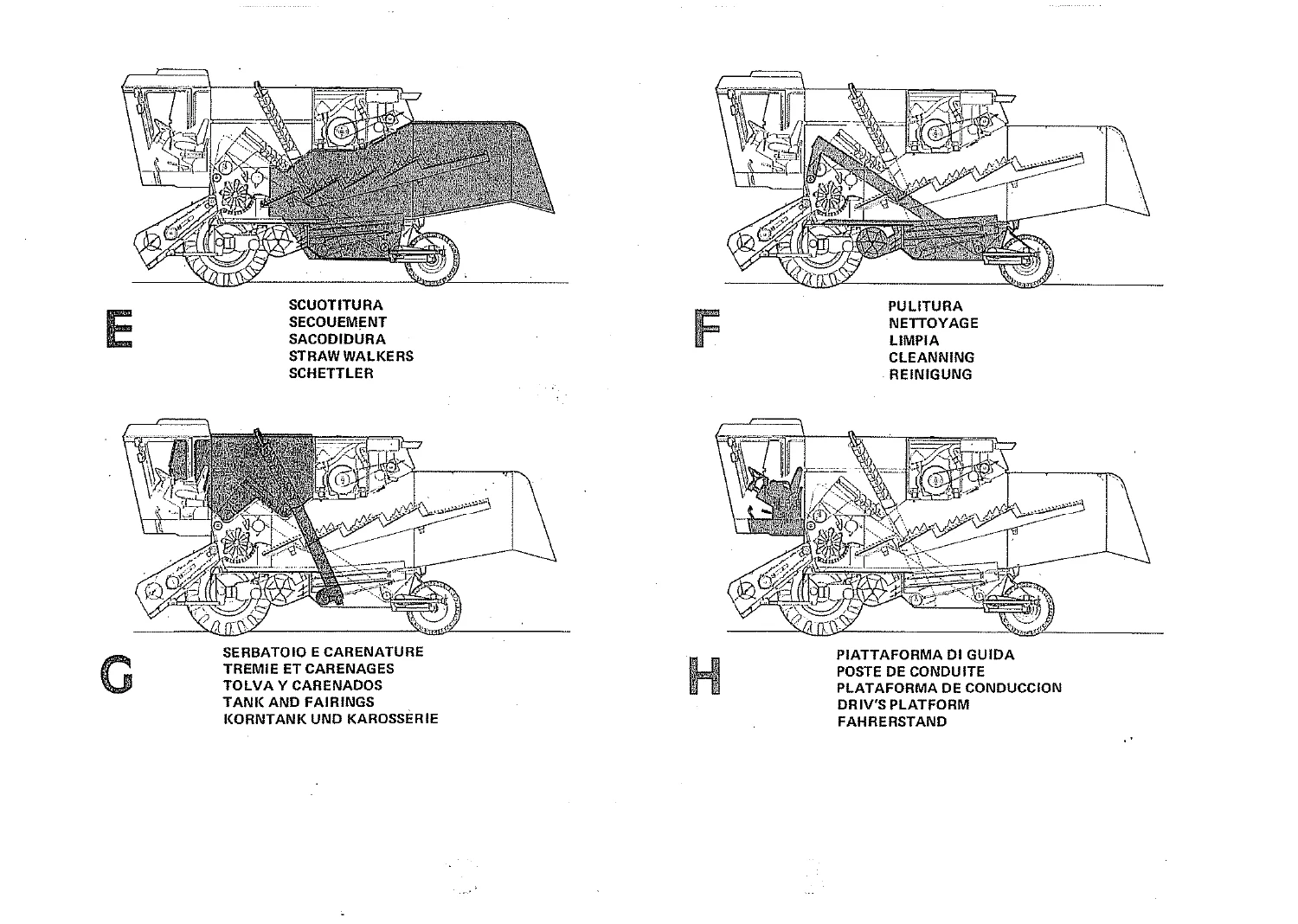
- Scuotitura, serbatoio e carenature, pulitura, piattaforma di guida
- Impianto idraulico and impianto elettrico – hydraulic and electrical systems
- Dotazione decalcomanie and varianti – decal set and machine variants
Taken together, these tables cover the whole machine rather than one corner of it. The engine section alone runs from the bare cylinder block through cylinder heads, pistons, timing, injection pump, governor elements, fuel filtration and cooling, while the machine sections continue into the variator, clutch, gearbox, differential, final drives, brakes, rear axle, chassis and the threshing and cleaning assemblies. For anyone rebuilding, restoring or simply keeping a 3700 or 3700R running, having the complete set of illustrated tables in one file is the difference between ordering a part and ordering the right part.
How the Part Number Tables Work
Each table carries a modification column and a set of abbreviations that are explained in the opening pages. Parts are listed with their order number, quantity and, where it applies, a note showing thickness in millimetres or diameter. Right and left hand are given relative to the direction of travel of the machine. Where a part was superseded during production, the catalogue shows the deleted item and the replacement after an equals sign, and states whether the change can also be applied to earlier machines. Chassis number breakpoints are given as the last number before a modification and the first number after it, so a machine can be matched to the correct version of a component without dismantling anything.
Engines and Machine Variants Documented
The engine tables are built around the FIAT-AIFO 8361.1, with separate listings for the injection equipment, the advance variator, the speed governor and the cooling and lubrication circuits. On the machine side, the catalogue separates the mechanical transmission from the hydrostatic transmission, so the variator, gearbox and pump drive tables you need depend on which version of the 3700 or 3700R you own. The crawler-equipped 3700R is also catered for, with dedicated tables for the drive wheel, track carriage, track chain, rollers and idler wheels, alongside the standard wheeled axle and tyre listings.
Why This Beats Working From Memory
Combine harvesters of this generation were built in overlapping production runs, with small changes introduced mid-series that are invisible from the outside. A bearing, a shim, a sealing ring or a lever can look identical and still not fit. The Laverda 3700 and 3700R Combine Harvester Parts Manual ties every one of those details to a table number and a chassis breakpoint, which is exactly the information a parts department would have used when the machine was current.
IMAGES PREVIEW
Instant PDF Delivery
Buy the Laverda 3700 and 3700R Combine Harvester Parts Manual and the file is available immediately after payment – no shipping, no waiting for a printed book to arrive, no risk of a torn or missing page. Read it on a laptop or tablet in the workshop, or print the specific tables you are working from and take them to the machine. With the complete illustrated parts catalogue on hand, identifying components, checking quantities, confirming modification status and ordering spares becomes a straightforward task rather than an educated guess.


Reviews
There are no reviews yet.