Lexmark Optra C710 Service Manual PDF DOWNLOAD
Original price was: $95.00.$16.95Current price is: $16.95.
Download the Lexmark Optra C710 service manual PDF for in-depth Optra C710 print quality service check, including Lexmark printer error codes troubleshooting and Optra C710 fuser unit removal guide. This guide covers models, operational theory, diagnostic aids with Lexmark C710 diagnostic mode instructions, repair information, connector locations, preventive maintenance, and Optra C710 parts catalog. Essential for technicians performing repairs, adjustments, and troubleshooting on the Optra C710 color laser printer.
Description
Lexmark Optra C710 Service Manual PDF DOWNLOAD
Description
This Lexmark Optra C710 service manual PDF download is a vital resource for service technicians and repair professionals maintaining the Lexmark Optra C710 color laser printer. Published in October 2000, it provides comprehensive coverage of general information, diagnostic information with Lexmark printer error codes troubleshooting, diagnostic aids including Lexmark C710 diagnostic mode instructions, repair procedures such as Optra C710 fuser unit removal guide, connector locations, preventive maintenance, and an extensive Optra C710 parts catalog to ensure accurate diagnostics and efficient repairs. Key sections include detailed Optra C710 print quality service check for issues like background fog, lines, spots, and density problems, along with service checks for components like fuser, printhead, motors, and sensors.
The manual emphasizes safety with notices on laser hazards and ESD handling, and includes operational theory on mechanisms like interlock, paper feed, carriage, toner cartridge, intermediate transfer unit, and fuser/paper exit unit. It also covers options like duplex units and paper trays, with symptom tables and service checks for base printer, covers, duplex, operator panel, paper feed, power, and print quality.
Bookmarks are present for quick navigation to major sections: Table of Contents, Index, Safety and Notices, Trademarks, Start Diagnostics, Manuals Menu.
Table of Contents (Extracted and categorized with bullet points for clarity):
- Notices and Safety Information (Page ix)
- Laser Notices (Page ix)
- General Information (Page 1-1)
- Models (Page 1-2)
- Standard Features (Page 1-2)
- Tools Required For Service (Page 1-6)
- Options (Page 1-7)
- Operational Theory (Page 1-8)
- Interlock Mechanism (Page 1-8)
- Sheet Bypass Paper Feed Unit (Page 1-9)
- Paper Feed Unit (Page 1-11)
- Second Paper Feed Unit (Optional Paper Trays) (Page 1-13)
- Drive Block (Page 1-17)
- Contact Cam (Page 1-18)
- Coupling Unit (Page 1-19)
- Carriage Unit (Page 1-21)
- Toner Cartridge Unit (Page 1-22)
- Intermediate Transfer Unit (Page 1-24)
- Fuser/Paper Exit Unit (Page 1-27)
- Detecting New Cleaning Unit (Page 1-28)
- Duplex Unit (Option) (Page 1-29)
- Diagnostic Information (Page 2-1)
- Start (Page 2-1)
- Service Error Codes (Page 2-2)
- User Status Messages (Page 2-7)
- User Attendance Messages (Page 2-13)
- Symptom Tables (Page 2-28)
- Base Printer Symptom Table (Page 2-28)
- Covers Interlock Symptom Table (Page 2-29)
- Duplex Unit Symptom Table (Page 2-29)
- Operator Panel Symptom Table (Page 2-30)
- Paper Feed Symptom Table (Page 2-30)
- Paper Tray Options Symptom Table (Page 2-31)
- Power Symptom Table (Page 2-31)
- Print Quality Symptom Table (Page 2-32)
- Service Checks (Page 2-34)
- Base Printer Service Checks (Page 2-35)
- Bypass Tray (Multipurpose Tray) Service Check (Page 2-35)
- Carriage Unit Service Check (Page 2-39)
- Coupling Unit Service Check (Page 2-42)
- Cover Interlock Service Check (Page 2-45)
- Developer/Paper Feed Motor Service Check (Page 2-48)
- Erase Lamp Service Check (Page 2-50)
- Fuser Cold Service Check (Page 2-51)
- Fuser Drive and Contact Cam System Service Check (Page 2-53)
- Fuser Hot Service Check (Page 2-57)
- High Voltage Leakage Detect Service Check (Page 2-58)
- ITM Drive Service Check (Page 2-60)
- Main Fan Service Check (Page 2-62)
- New Toner Cartridge Detection Service Check (Page 2-63)
- Operator Panel Service Check (Page 2-64)
- Operator Panel Buttons Service Check (Page 2-65)
- OPC Drive Service Check (Page 2-66)
- Paper Exit Sensor Service Check (Page 2-67)
- Paper Feed Service Check (Page 2-68)
- Parallel Port Service Check (Page 2-71)
- Power Service Check (Page 2-72)
- Printhead Service Check (Page 2-77)
- Print Quality Service Checks (Page 2-79)
- Print Quality Initial Service Check (Page 2-79)
- All Black or Color Page Service Check (Page 2-80)
- All Blank Page Service Check (Page 2-81)
- Background Service Check (Page 2-82)
- Black, Color Lines or Bands Service Check (Page 2-83)
- Black or Color Spots Service Check (Page 2-84)
- Developer Drive System Service Check (Page 2-84)
- Evenly Spaced Horizontal Lines/Marks Service Check (Page 2-85)
- Foggy Background Service Check (Page 2-86)
- Low Image Density Service Check (Page 2-87)
- Offset Print Service Check (Page 2-88)
- Poor Color Reproduction Service Check (Page 2-89)
- Random Marks Service Check (Page 2-90)
- Residual Image Service Check (Page 2-90)
- Skew Service Check (Page 2-91)
- Toner on Backside of Page Service Check (Page 2-91)
- Uneven Print Density Service Check (Page 2-92)
- White Lines or Bands Service Check (Page 2-92)
- White Spots Service Check (Page 2-94)
- White/Black Lines Service Check (Page 2-95)
- Serial Port Service Check (Page 2-96)
- Toner Level Detect Service Check (Page 2-96)
- Toner Low/Empty Sensor Service Check (Page 2-97)
- Transfer Roll Service Check (Page 2-98)
- Tray 1 (Integrated Tray) Service Check (Page 2-99)
- Options Service Checks (Page 2-106)
- Flash Memory Option(s) Service Check (Page 2-106)
- DRAM Memory Option(s) Service Check (Page 2-106)
- Hard Disk Option Service Check (Page 2-107)
- Network Card Option Service Check (Page 2-108)
- 250/250 Dual Paper Tray Service Check (Page 2-108)
- 250/250 Paper Tray Symptom Table (Page 2-109)
- Duplex Unit Option Service Check (Page 2-120)
- Diagnostic Aids (Page 3-1)
- Print Quality Test Pages (Page 3-1)
- Paper Jam Sequence (Page 3-1)
- Disabling Download Emulations (Page 3-3)
- Diagnostics Menu Structure (Page 3-3)
- Diagnostic Mode (Page 3-4)
- Print Registration (Page 3-6)
- Print Tests (Page 3-8)
- Print Quality Test Pages (Page 3-9)
- Hardware Tests (Page 3-10)
- LCD Test (Page 3-10)
- Button Test (Page 3-10)
- Parallel Wrap Test (Page 3-11)
- ROM Memory Test (Page 3-12)
- SDRAM Memory Test (Page 3-13)
- Serial Wrap Test (Page 3-14)
- Duplex Tests (Page 3-15)
- Quick Test (Page 3-15)
- Duplex Feed 1 (Page 3-15)
- Duplex Feed 2 (Page 3-15)
- Device Tests (Page 3-16)
- Quick Disk Test (Page 3-16)
- Disk Test/Clean (Page 3-17)
- Flash Test (Page 3-18)
- Printer Setup (Page 3-19)
- Setting the Page Count (Page 3-19)
- Viewing the Permanent Page Count (Page 3-19)
- Serial Number (Page 3-19)
- Setting Configuration ID (Page 3-20)
- Laser Power (Page 3-21)
- Parallel Strobe Adjustment (Page 3-21)
- Error Log (Page 3-22)
- Viewing the Error Log (Page 3-22)
- Clearing the Error Log (Page 3-22)
- Restore EP Factory Defaults (Page 3-22)
- Exiting Diagnostic Mode (Page 3-23)
- Repair Information (Page 4-1)
- Handling ESD-Sensitive Parts (Page 4-1)
- Cover Removals (Page 4-2)
- Cartridge Cover Removal (Page 4-3)
- Front Cover Removal (Page 4-3)
- Fuser Cover Removal (Page 4-3)
- Left Side Cover Removal (Page 4-3)
- Operator Panel Cover Removal (Page 4-3)
- Rear Cover Removal (Page 4-3)
- Right Side Cover Removal (Page 4-4)
- Top Cover Removal (Page 4-4)
- Top (Small) Cover Removal (Page 4-4)
- Right Side Removals (Page 4-5)
- Carriage Drive Motor Removal (Page 4-6)
- Coupling Drive Motor Removal (Page 4-7)
- Developer Drive Motor Assembly Removal (Page 4-7)
- Fuser Drive Motor Removal (Page 4-8)
- OPC Drive Motor Removal (Page 4-9)
- Cam Sensor Removal (Page 4-9)
- LVPS Assembly Removal (Page 4-10)
- Main Fan Removal (Page 4-12)
- Main Fan Mounting Bracket Removal (Page 4-12)
- Motor Mounting Stay C Assembly Removal (Page 4-13)
- OPC Coupling Drive Block Assembly Removal (Page 4-14)
- Solenoid Removal (Page 4-14)
- Left Side Removals (Page 4-15)
- Grid Block 1 Assembly Removal (Page 4-16)
- Grid Block 2 Assembly Removal (Page 4-17)
- Cable Cover 3 Removal (Page 4-18)
- Cover Interlock Switch Removal (Page 4-18)
- Micro Switch Removal (Page 4-18)
- Electronics Removals (Page 4-19)
- Controller Board Assembly Removal (Page 4-19)
- Engine Board Assembly Removal (Page 4-19)
- HVPS Board Assembly Removal (Page 4-20)
- Interconnect Board Assembly Removal (Page 4-21)
- On/Off Coupling Sensor Board Removal (Page 4-21)
- Paper Sensor Board (Page 4-21)
- Resist Sensor Board Removal (Page 4-22)
- Waste Toner Board Assembly Removal (Page 4-22)
- Fuser Unit (Page 4-23)
- Fuser Unit Removal (Page 4-23)
- Fuser Lamp Removal (Page 4-23)
- Thermistor and Thermostat Removal (Page 4-23)
- Main Body (Page 4-24)
- Paper Feed Block Assembly Removal (Page 4-24)
- Printhead Removal (Page 4-24)
- Print Cartridge Carousel Removal (Page 4-25)
- Carriage Home Position Sensor Removal (Page 4-26)
- Registration Roll Removal (Page 4-27)
- Connector Locations (Page 5-1)
- Engine Board (Page 5-1)
- LVPS (Low Voltage Power Supply) (Page 5-3)
- Erase Lamp Board (Page 5-3)
- TRAY 1 Sensor Board (Page 5-3)
- TRAY 1 Registration Sensor Board (Page 5-4)
- Waste Toner Sensor Board (Page 5-4)
- Belt Position Sensor Board (Page 5-5)
- Connector Locations for Options (Page 5-6)
- 2nd Paper Option (250/250 Paper Option) (Page 5-6)
- 2nd Paper Option (250/250 Paper Option) (Page 5-7)
- LVPS (Internal 2nd Tray Option) (Page 5-7)
- Duplex Unit Option (Page 5-8)
- LVPS (Internal Automatic Duplex Option) (Page 5-9)
- Electrical Components (Page 5-10)
- Sensor/Switch Locations (Page 5-10)
- Printer Circuit Board Locations (Page 5-13)
- Fan/Motor Locations (Page 5-13)
- Solenoid/Clutch Locations (Page 5-14)
- 250/250 Paper Tray Option (Page 5-15)
- Duplex Option (Page 5-15)
- Cable Connections (Page 5-16)
- Preventive Maintenance (Page 6-1)
- Safety Inspection Guide (Page 6-1)
- Service Precautions (Page 6-1)
- Cleaning Procedures (Page 6-1)
- Lubrication Specifications (Page 6-1)
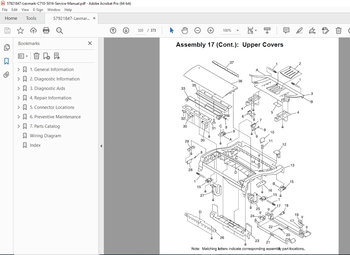
- Parts Catalog (Page 7-1)
No separate index is extracted from the provided sections, but an Index bookmark is listed on page 1, likely at the end of the manual.
This manual is crucial for Optra C710 print quality service check and Lexmark printer error codes troubleshooting, ensuring safe and precise repairs using Lexmark C710 diagnostic mode instructions and Optra C710 fuser unit removal guide. Equip yourself with this detailed Lexmark Optra C710 service manual PDF to handle diagnostics and repairs with confidence—your go-to resource for maintaining peak performance in your Optra C710 printer
File Details
- Manual name: Lexmark Optra™ C710 Service Manual
- Models covered: Optra C710
- Year: 2000
- Manual PDF quality: High (clear text, diagrams, and formatting)
- No of pages: 373