LG E500 Smartphone Service Manual PDF DOWNLOAD
Original price was: $95.00.$13.95Current price is: $13.95.
Official LG Electronics internal service manual for the LG-E500 GSM smartphone. Covers complete hardware features, technical specifications, functional block diagram, baseband and RF circuit theory, power management IC, 13 illustrated troubleshooting flowcharts, firmware download procedure, RF calibration, standalone RF test, circuit schematics, PCB layout, BGA pin maps, exploded view, and replacement parts list with part numbers. 183 pages — instant PDF download.
Description
LG E500 Smartphone Service Manual GSM Repair Troubleshooting 2010 PDF DOWNLOAD
DESCRIPTION:
LG-E500 Smartphone — Official Service Manual (Issue 1.0, November 2010)
This is the complete official LG Electronics internal service manual for the LG-E500 GSM Smartphone, published by LG Electronics as an internal training and service reference (Issue 1.0, November 2010). Intended for LG-authorized service centers, mobile phone repair technicians, and electronics engineers, this comprehensive document covers the full scope of LG-E500 hardware description, circuit theory, fault diagnosis, RF calibration, firmware flashing, and component replacement.
📋 File Details
| Detail | Information |
|---|---|
| Manual Name | LG-E500 Service Manual |
| Model | LG-E500 |
| Publisher | LG Electronics Inc. |
| Issue | Issue 1.0 |
| Year | November 2010 |
| PDF Quality | Digitally produced, searchable, high resolution |
| Total Pages | 183 |
| File Format | PDF (landscape A3, 1207×842 pts) |
📑 Complete Table of Contents
Chapter 1 — Introduction
- 1.1 Purpose
- 1.2 Regulatory Information (security, incidence of harm, service changes, maintenance limitations, radiated emissions, ESD handling)
- 1.3 Abbreviations (full glossary: APC, BER, DCXO, EGPRS, ESD, FPCB, GMSK, GPRS, GSM, OPLL, PAM, PCB, PLL, SAW, SIM, SRAM, UART, VCO, WAP, 8PSK, and more)
Chapter 2 — Performance
- 2.1 H/W Feature (hardware feature summary table)
- 2.2 Technical Specification (27 performance parameters with full measured values — see specifications table below)
Chapter 3 — Technical Brief (deep-dive circuit theory, 16 subsystems)
- 3.1 LG-E500 Functional Block Diagram (complete chip-level interconnect diagram: S-GOLD3 baseband, TCC7921 multimedia, PMB6952 transceiver, WM8993 audio codec, BCM20780 BT/FM, PMB8877 PMIC, RT9396 charge pump)
- 3.2 Baseband Processor (BBP) Introduction (Infineon S-GOLD3 architecture, GPIO assignments, interface details)
- 3.3 Power Management IC (PMB6821 PMIC — voltage domains, LDO outputs, battery management)
- 3.4 Power ON/OFF (power sequencing)
- 3.5 SIM & Micro SD Interface (3V Small SIM, microSD interface circuit)
- 3.6 Memory (2Gbit NAND Flash + 1Gbit DDR SDRAM MCP — K522H1HACB — 8/16-bit parallel data bus ADD[0:29])
- 3.7 LCD Display (3.0″ WQVGA 240×400, 262K color TFT, 6-LED edge backlight, SHARP LS030B3UW01, S6D14E0 controller, 20,000:1 contrast)
- 3.8 Keypad Switching & Scanning
- 3.9 Keypad Back-Light Illumination
- 3.10 LCD Back-Light Illumination (PWM-controlled white LED driver)
- 3.11 JTAG & ETM Interface Connector
- 3.12 Audio (WM8993 audio codec — speaker, receiver, headset, FM audio, A-TV audio paths)
- 3.13 Audio Amplifier
- 3.14 Microphone Circuit (main MIC + headset MIC signal paths)
- 3.15 Charging Circuit (CC-CV charge algorithm, fast charge <400mA, slow charge <120mA, travel adapter 5.1V/700mA)
- 3.16 FM Radio & Bluetooth (BCM20780 combined FM/BT chip)
- 3.17 μ-USB Multimedia Interface Connector
- 3.18 Multimedia Chip (TCC7921) (A-TV decoder, video output, multimedia interfaces)
- 3.19 General Description
- 3.20 Receiver Part
- 3.21 Transmitter Part
- 3.22 RF Synthesizer
- 3.23 DCXO (Digitally Controlled Crystal Oscillator — 26 MHz reference, ≤2.5 ppm tolerance)
- 3.24 Front End Module Control (FEM switching between Rx/Tx paths)
- 3.25 Power Amplifier Module (EDGE PAM — GSM850/900 33 dBm @ PCL5; DCS/PCS 30 dBm @ PCL0)
- 3.26 PAM Schematic
- 3.27 Broadcasting (A-TV TLG1121 tuner)
Chapter 4 — Trouble Shooting (13 fault categories with step-by-step flowcharts)
- 4.1 Trouble Shooting Test Setup
- 4.2 Power On Trouble (no power, power cycling, abnormal shutdown)
- 4.3 Charging Trouble (no charge, slow charge, battery not recognized)
- 4.4 LCD Display Trouble (blank display, partial display, backlight failure)
- 4.5 Camera Trouble (no image, camera not detected)
- 4.6 Receiver & Speaker Trouble (no audio, distorted audio, earpiece/loudspeaker failure)
- 4.7 Microphone Trouble (no transmit audio, low MIC sensitivity)
- 4.8 Vibrator Trouble (vibrator not working)
- 4.9 Keypad Back-Light Trouble
- 4.10 SIM & microSD Trouble (SIM not detected, microSD card error)
- 4.11 Touch Trouble (unresponsive touch, incorrect registration)
- 4.12 Receiver Part (RX path signal tracing)
- 4.13 Transmitter Part (TX path signal tracing — power level, modulation, spectrum)
- 4.14 Broadcasting Part (A-TV signal chain diagnosis)
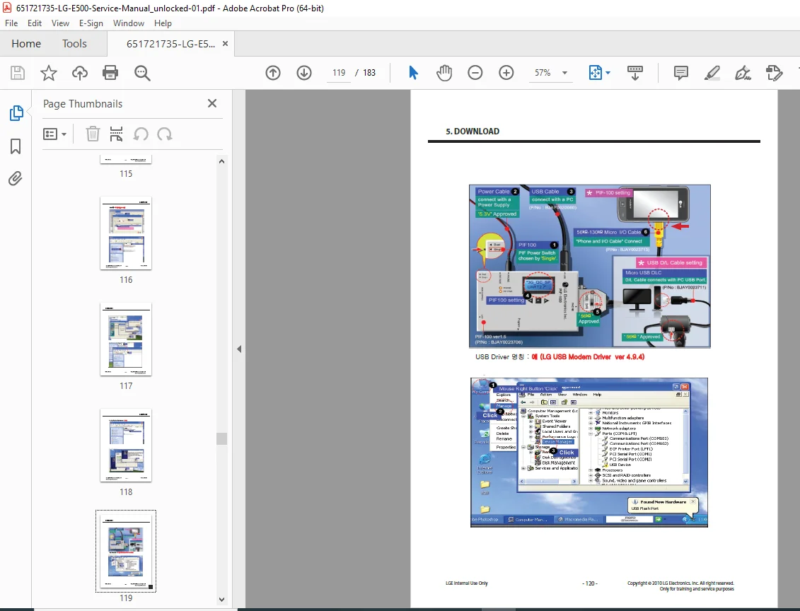
Chapter 5 — Download
- Firmware download procedure (Re-Download S/W & CAL, Re-Download S/W & RF)
- Service PC connection setup
- Flash tool operation
- Firmware verification
Chapter 6 — Block Diagram (System-level block diagram — full chip interconnects)
Chapter 7 — Circuit Diagram (Complete schematic diagrams — power supply, baseband, RF, audio, display, USB, SIM, camera, and peripheral circuits)
Chapter 8 — BGA Pin Map (Ball grid array pin mapping for key ICs — S-GOLD3 BBP, PMIC, MCP memory)
Chapter 9 — PCB Layout (Top and bottom layer PCB layout with component locations)
Chapter 10 — RF Calibration
- 10.1 Test Equipment Setup (GPIB-controlled test bench configuration)
- 10.2 Calibration Steps (GSM/EGPRS TX power calibration per band and power level; DCXO AFC calibration; RX path calibration)
Chapter 11 — Stand Alone Test
- 11.1 Test Program Setting
- 11.2 Tx Test (standalone transmitter output power and modulation verification)
- 11.3 Rx Test (standalone receiver sensitivity measurement)
Chapter 12 — Exploded View & Replacement Parts List
- 12.1 Exploded View (illustrated full assembly breakdown)
- 12.2 Replacement Parts (complete hierarchical parts list with LG part numbers — mechanical, PCB assemblies, LCD module, touch window, camera module, keypad, frame, brackets, tapes, gaskets, covers)
- 12.3 Accessory (travel adapter, battery, data cable, headset)
⚡ Key Technical Specifications at a Glance
| Specification | Value |
|---|---|
| Model | LG-E500 |
| Frequency Bands | GSM900, EGSM, DCS1800, PCS1900 |
| TX Power (GSM/EGSM) | 33 dBm @ PCL5 |
| TX Power (DCS/PCS) | 30 dBm @ PCL0 |
| RX Sensitivity | EGSM/GSM850: -108 dBm; DCS/PCS: -107 dBm |
| GPRS Class | Class 12 |
| Speech Coding | HR / EFR / FR / AMR |
| Display | 3.0″ WQVGA, 240×400, 262K color TFT |
| Display Contrast | 20,000:1 |
| Camera | 3 Megapixel (Sony 1/5″ sensor, LM33SNFF) |
| Battery | Li-Ion, 3.7V, 1100 mAh |
| Talk Time | 4 hours (GSM TX Level 7) |
| Standby Time | Up to 320 hours |
| Charge Time | Under 3 hours (Fast charge <400 mA) |
| Travel Adapter | 100–240V AC, 50/60Hz → 5.1V, 700mA |
| SIM Card | 3V Small SIM |
| Memory | 2Gbit NAND Flash + 1Gbit DDR SDRAM (MCP) |
| Bluetooth | Yes (BCM20780) |
| FM Radio | Yes (BCM20780) |
| USB | μ-USB 2.0 HS |
| Sensors | 3-Axis accelerometer, resistive touch |
| Frequency Error | <0.1 ppm |
| Phase Error | RMS <5°, Peak <20° |
🔑 Why Mobile Repair Technicians Need This Manual
- ✅ 13 fault-category troubleshooting flowcharts — power, charging, LCD, camera, speaker, microphone, vibrator, keypad backlight, SIM/microSD, touch, RX/TX RF path and A-TV
- ✅ Full circuit schematics — trace any fault from symptom to component level across all subsystems
- ✅ BGA pin maps — essential for board-level rework and reballing of S-GOLD3 and PMIC packages
- ✅ PCB layout — locate test points and components by reference designator
- ✅ Complete RF calibration procedure — restore TX power accuracy and DCXO frequency after mainboard repair or replacement
- ✅ Standalone Tx/Rx test — verify RF performance without service software
- ✅ Firmware re-flash procedure — recover dead units or update S/W + CAL + RF calibration data
- ✅ Full replacement parts list with LG part numbers — order the exact OEM component from GCSC/SBOM
- ✅ Power management IC detail — understand all voltage rails and LDO outputs for efficient power fault diagnosis
Stop guessing and start tracing. Whether you’re recovering a no-power LG-E500 or recalibrating TX output after a mainboard swap, this official LG Electronics internal service manual gives you every schematic, test point, calibration step, and part number you need. Download instantly after purchase.