
Liebherr LH22 LH24 LH26 LH30 LH35 M/C/T Hydraulic Excavator Service Manual 11652059 — 2536-Page Workshop PDF
Original price was: $76.95.$44.95Current price is: $44.95.
Complete Liebherr service manual for the LH22, LH24, LH26, LH30 and LH35 M/C/T hydraulic excavators — order no. 11652059. 2536 pages covering diesel engine, hydraulics, electrical, axles, slewing gear and diagnosis. Instant PDF download.
Description
Liebherr LH22 LH24 LH26 LH30 LH35 M/C/T Hydraulic Excavator Service Manual — Order No. 11652059
This is the complete Liebherr service manual for the LH22, LH24, LH26, LH30 and LH35 wheeled and crawler hydraulic excavator range, covering the M, C and T variants across eight machine types in a single document. The manual runs to 2536 pages under order number 11652059, original edition 01/2013, with a last update of 05/2020. Because the manual is maintained as a loose-leaf document, every chapter carries its own amendment date between 2013 and 2020, so you can see exactly which pages apply to which serial-number range of the machine. It is the same workshop-level reference that Liebherr service technicians use to service, adjust, diagnose and overhaul these machines, and it is published in English.
File Details
- Manual type: Complete service manual — workshop, repair and diagnostics
- Brand: Liebherr
- Manufacturer: LIEBHERR Hydraulikbagger GmbH, Kirchdorf / Iller, Germany
- Machine types covered: LH22-1197, LH22C-1209, LH24-1198, LH26-1199, LH30-1200, LH30C-1210, LH35-1201, LH35T-1220
- Language: English
- Page count: 2536 pages
- File format: PDF
- Order number: 11652059
- Edition: 01/2013
- Last update: 05/2020
Chapters Covered
- 010 — Introduction
- 020 — Technical data
- 030 — Maintenance
- 040 — Drive group
- 050 — Cooling system
- 060 — Working hydraulics
- 070 — Travel hydraulics
- 080 — Hydraulic components
- 090 — Steering system
- 100 — Brake system
- 110 — Electrical system
- 120 — Travel gear mechanism
- 130 — Axles / Drive
- 140 — Steel parts — basic machine
- 150 — Working equipment
- 160 — Cab / heating / air conditioning
- 170 — Lubrication system
- 180 — Slewing gear mechanism / Slewing ring
- 190 — Equipment / Options
- 200 — Diagnosis
010 — Introduction, Standards, Special Tools and Preservation
Group 010 opens with the current standards and regulations index, the amended-page directory in 010.010 that tracks every revision back to the original 2013 issue, and the general safety instructions. It then documents the special tool sets — general pressure and measuring equipment, hydraulic tools, electrical tools, diesel engine tools, slewing gearbox tools, multi-disc brake mounting devices and ZF/Kessler axle tools — with their item codes and application notes. The preservation guidelines for decommissioning, storing for up to 2 months, 12 months or more than 12 months, and putting the machine back into service, plus the cylinder preservation procedures, close out the group.
020 — Model-Specific Technical Data
Group 020 lists the machine-specific technical data separately for each type: LH22 M 1197, LH24 M 1198, LH26 M 1199, LH30 M 1200 / LH35 M/T 1201 and 1220, LH22 C 1209 and LH30 C 1210. Each entry shows the effective weight range, overall dimensions, ground clearance, diesel engine designation, rated speed, maximum torque, hydraulic pump type and maximum flow, control block type, gearbox and travel motor type, axle designations, slewing gearbox and oil motor type, and slewing ring type.
030 — Maintenance, Inspection Schedules, Fuels and Lubricants
Group 030 contains the inspection and maintenance schedules broken down by model family — LH22 M / LH24 M / LH26 M, LH22 C, LH30 / LH35 M/T, and LH30 C. Each schedule lists the work to be carried out at acceptance, every 8–10 hours, every 50, 500, 1000, 2000 and 3000 hours, and at special intervals. The group also contains the check and adjustment task records, the filling quantities for hydraulic system, diesel engine, fuel tank, coolant, slewing gearbox, transmission, rigid axle, steering axle, travel gearbox and air-conditioning unit, plus the oil sampling procedures and the approved fuels, lubricants and operating fluids with their minimum quality requirements.
040 — Drive Group, Diesel Engine and Exhaust Aftertreatment
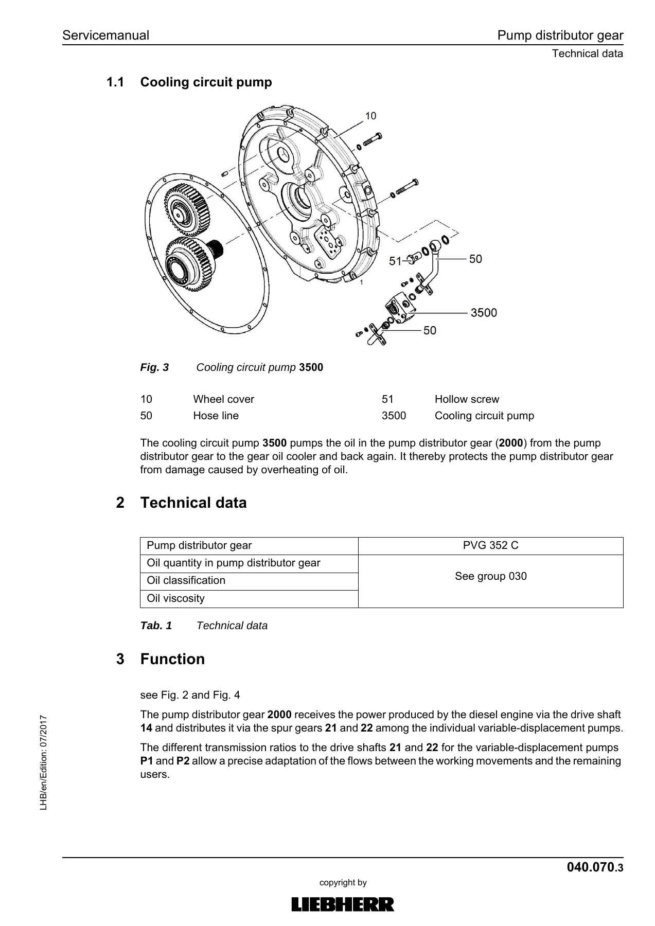
Group 040 covers the Liebherr D834 A7 4-cylinder in-line diesel engine — 108 mm bore, 125 mm stroke, 4580 cm³ displacement, 17.5:1 compression ratio, common-rail injection — and the D934 A7 4-cylinder engine — 122/150 mm bore/stroke, 7000 cm³ displacement, 17.4:1 compression ratio — including component and sensor arrangements, engine control unit A700 plug connections, high-pressure pump with VCV and PCV valves, engine fixtures and rubber pads, fuel system with pre-filter, fine filter and water separator, air filter unit with main and safety element, exhaust gas system with oxidation catalyst, and the Liebherr diesel particulate filter — both the earlier DPF and the version with HC doser injection system and regeneration valve 5030. The pump distributor gear with its cooling circuit pump 3500 and cooling oil cooler is also documented here.
050 — Cooling System and Hydraulic Fan Drive
Group 050 describes the cooling unit assembly — coolant cooler, intercooler, fuel cooler, hydraulic oil cooler and air-conditioning condenser — the coolant circuit and intercooling air circuits of the diesel engine, the fuel cooling circuit and the hydraulic oil cooling circuit. The fan control section covers the fan wheel, fan motor with proportional solenoid valve Y352, the priority valve 7400 for steering and fan circuits, and the optional reversible fan drive with valve block 3180 and its automatic airflow reversal function. Operating temperatures (warning 90 °C, alarm 95 °C for hydraulic oil) and the fan speed/pressure adjustment values are covered in the check and adjustment tasks in group 030.
060 — Working Hydraulics and Hydraulic Schematic Sets
Group 060 opens with the overview of hydraulic symbols and the colour code of hydraulic schematics. It then provides the complete hydraulic schematic sets by model — LH22 M, LH24 M / LH26 M, LH30 M, LH35 M / LH35 T, LH22 C / LH26 EC, and LH30 C — each with its component list showing every pump, valve, cylinder, motor, accumulator, filter, measuring point and electrical connector. Group 060.003 covers the procedure for reducing pressure in the hydraulic system, including depressurising the hydraulic tank.
070 — Travel Hydraulics: Regulating Motors
Group 070 covers the travel motor range. The CMVE 085 hydraulic regulating motor (fitted to LH22 C and LH30 C) is documented with its rotary group, pivoting angle adjustment, multi-disc brake, directional valve and pressure reducing valve, plus design, function, technical data and maintenance. The DMVA travel motor with EL/DA regulation (LH22 M through LH35) is covered in detail: rotary group, control cylinder and regulating unit, proportional solenoid valve Y543, brake valve, secondary pressure-relief valves, creeper gear and DA regulation, and leakage check.
080 — Hydraulic Components: Tank, Pumps, Valves, Cylinders
Group 080 is the largest hydraulic group. It documents the hydraulic tank (with return filter, breather filter, bypass valve, magnetic rod and oil level sight glass), putting hydraulic pumps into service, the DPVO variable-displacement pump with its performance regulator and flow regulator, the DPVP 108 double variable-displacement pump, the A10VO fan pump with pressure cut-off and flow regulator, the control oil unit, the 4x servo control unit, the LSC control block with its input section and control axles, the LSC pilot plate, the auxiliary control axle AS1 (medium pressure) and AHS11 (high pressure), the slewing gear motors, the rotary connection 13x and 6x, hydraulic differential cylinders with their seals and end-of-travel cushioning, accumulators (diaphragm, bladder and piston types), and the line break safety valves.
090 — Steering System
Group 090 covers the hydrostatic steering system with steering column, brake and power steering pump 3400 (LH30 / LH35) or fan and power steering pump 3100 (LH22 M / LH24 / LH26 M), steering valve 3750, steering cylinder 3770, priority valve 7400, and the joystick steering option with proportional valve 3800 and solenoid valves Y552, Y553, Y554. The four-wheel steering option is documented with the rigid axle steering cylinder and changeover valve.
100 — Brake System
Group 100 covers the dual-circuit hydraulic brake system: brake pump 3300, compact brake block 3420 with its compensator, accumulator charging valve 3424 and pressure regulator, accumulators 3450 (front axle) and 3460 (rear axle), and the multi-disc brakes at the axles. It also describes the switching behaviour between switch-on and shut-off pressures, the pedal-actuated proportional pressure build-up, accumulator charging and bleeding procedures.
110 — Electrical System
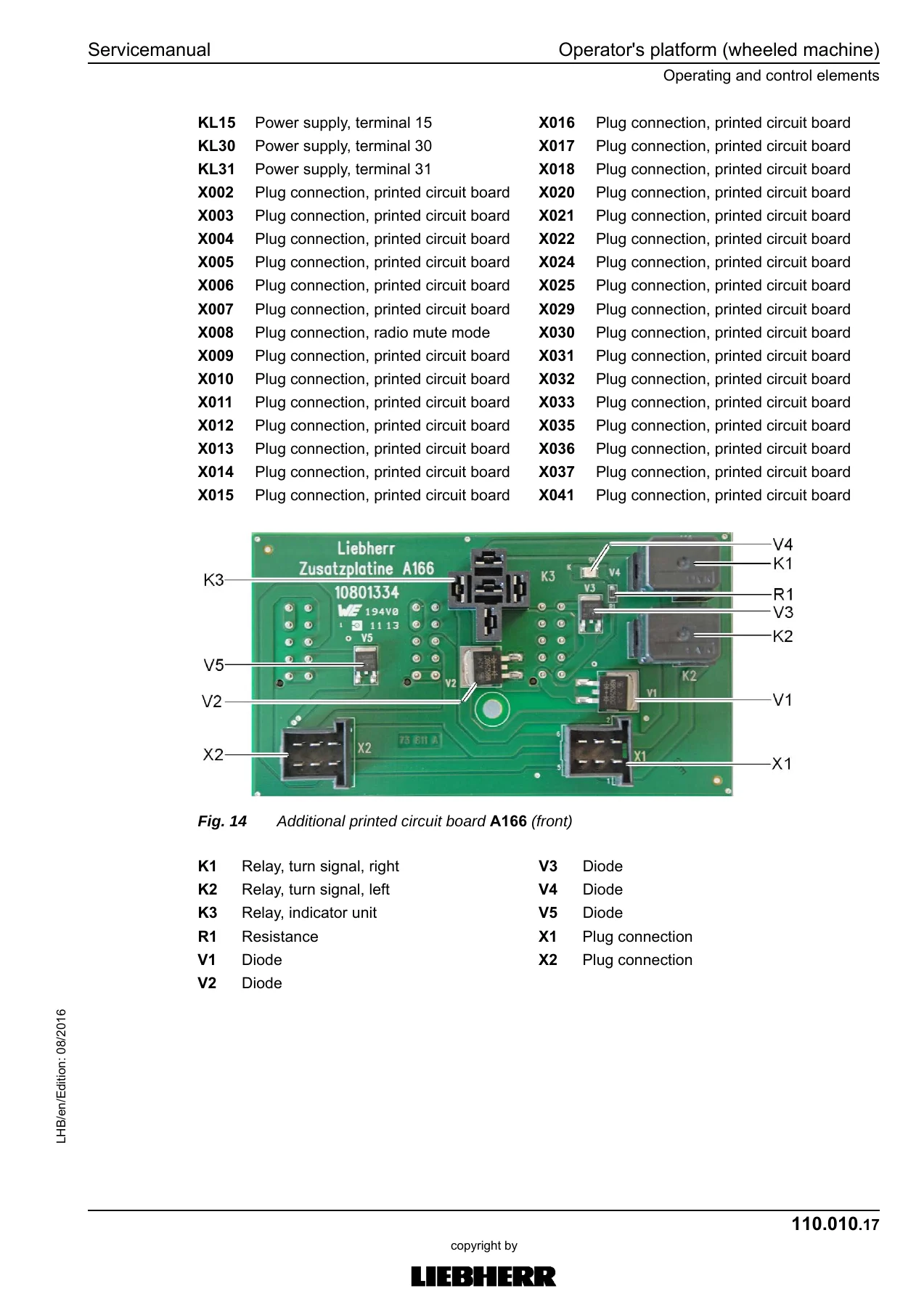
Group 110 provides the electrical symbol reference, operator’s platform layouts for wheeled and crawler machines with all control units A168–A172, the central electrics motherboard A161 (front and rear views), the additional printed circuit board A166, the input modules A163 / A164 / A165, master module A178 with its LEDs and plug connections, display A162, and the CAN bus overview. Circuit diagrams for the operator’s platform and the basic machine are followed by the D834 diesel engine circuit diagram, the D934 A7 129 kW and 175 kW versions, the slip ring rotary connection diagram, malfunction troubleshooting, and the info menu with electrical inputs and outputs.
120 — Travel Gear Mechanism and Transmission
Group 120 covers the ZF transmission 2HL 290 with gear shifting, parking brake and joint shafts, including the travel motor interface, gear shifting pressures, function tests and oil specification. Speed sensor B259 mounting and travel motor pivoting angle control are also documented here.
130 — Axles and Drive
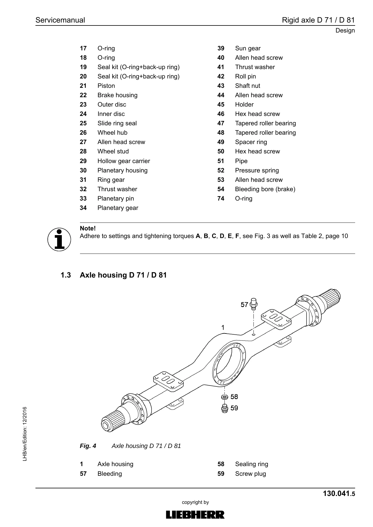
Group 130 documents the steering axle (MS-E 3060 / 3070) and rigid axle (MT-E 3070) fitted to the M-range machines, plus the Kessler LT71 / D71 axles on the LH35 M/T. It covers differential and wheel hub oil volumes, multi-disc brakes and their wear limits, steering knuckle bearings, oscillation axle support and cylinder, wheel nuts and tyre pressure, plus technical data, wear limits and running gear parts for the LH22 C / LH30 C crawler undercarriage — track chain, idler wheel, track rollers, carrier rollers and face seals.
140 — Steel Parts and Basic Machine
Group 140 covers the steel structure of the basic machine: undercarriage, uppercarriage, counterweight, working attachment mounting points, bearing covers and pins, and the repair welding guideline for the load-bearing steel parts of the LH22 M through LH35 M machines.
150 — Working Equipment and Attachments
Group 150 documents the working attachment — boom, stick, bucket, grapple, adjustable boom cylinder, quick coupler interfaces and third-party attachment interfaces. It also covers the dozer blade and stabiliser support variants (LH22 M through LH26 M), outrigger support variants, the hydraulic quick coupler, and the bucket / grapple changeover function.
160 — Cab, Heating, Ventilation and Air Conditioning
Group 160 covers the operator’s cab — with hydraulic cab elevation on the optional version — including window glass, wipers, mirrors, seals, gas pressure springs, cab suspension and the mounting instructions with special screwed connections. The heating, ventilation and air-conditioning section documents the a/c compressor drive, fresh air and recirculated air filters, condenser, expansion tank and the automatic climate control panel.
170 — Lubrication System
Group 170 covers the central lubrication system, the SX-E and MX-F progressive distributors, the lubrication hoses with their repair instructions, and the specific lubrication points on the working attachment and support cylinders.
180 — Slewing Gear Mechanism and Slewing Ring
Group 180 documents the slewing gearbox SAT 225 / 250 / 275 / 300 / 325 / 350 range and their oil motor options — FMF 045, HMF 75-02P — the multi-disc slewing brake with its mounting device and the slewing ring with its maximum tilting play, mounting bolt torque and greasing.
190 — Diagnosis and SCULI Setup Wizard
Group 190 walks through Liebherr’s SCULI diagnostic software and the setup wizard. It includes master module reset, CAN module addressing, address assignment, driver identification, data logger functions, and step-by-step check and adjustment wizard procedures for the hydraulic system, engine, brake, servo control, gear shifting, fan control, steering, working pump, control block, slewing gear, operating pressure and Tool Control.
200 — Equipment and Options
Group 200 documents the electrical and hydraulic equipment options and attachments: tool control, hydraulic quick coupler, LIKUFIX, mowing bucket, magnet system, generator drive accessory kit, refuelling pump, bypass filter, stick shut-off, height limitation and hoist cylinder protection deactivation. It also covers the control units for pre-heating of hydraulic oil, fuel, coolant and engine oil, and the data transmission system.
What This Liebherr Service Manual Lets You Do
If you own or service an LH22, LH24, LH26, LH30 or LH35 excavator in any of its M, C or T versions, this manual answers the workshop questions that a parts list or operator’s book simply cannot. Use it to set pump pressures and check the LSC control block, diagnose a DMVA or CMVE travel motor, service the D834 A7 or D934 A7 diesel engine, replace hydraulic cylinder seals and end-of-travel cushioning, bleed the brake circuit, or trace an electrical fault through the CAN bus. Every adjustment value in the check and adjustment tasks has a matching procedure, and every major assembly — rotary connection, slewing gearbox, oscillating axle, pump distributor gear, rigid axle — is documented with sectional drawings, exploded views and, where applicable, electrical or hydraulic schematics.
The advantage of the Liebherr-published service manual over online forum guesses is that the specifications, torque values and procedural sequences are the same ones the manufacturer uses in its own workshops. Getting them wrong risks damaged hydraulic components, uneven axle wear, brake drag, or a mis-set engine that smokes and consumes fuel. Because the manual is amendment-dated and serial-number-linked per model, you can confirm the exact page that applies to a given machine, and if you work across the LH22 to LH35 range you get all eight variants in one document — no need to buy separate books for each type.
IMAGES PREVIEW
Delivery is by instant PDF download after payment. There is no shipping, no waiting for a parcel, and no risk of a book going out of print. The 2536-page file opens on any laptop, tablet or phone, can be printed to A4 for the workshop bench, and taken offline on site. Every chapter illustration, hydraulic and electrical schematic, and table is reproduced from the original document, so what you read on screen is what you would see on paper.
Reviews
There are no reviews yet.