
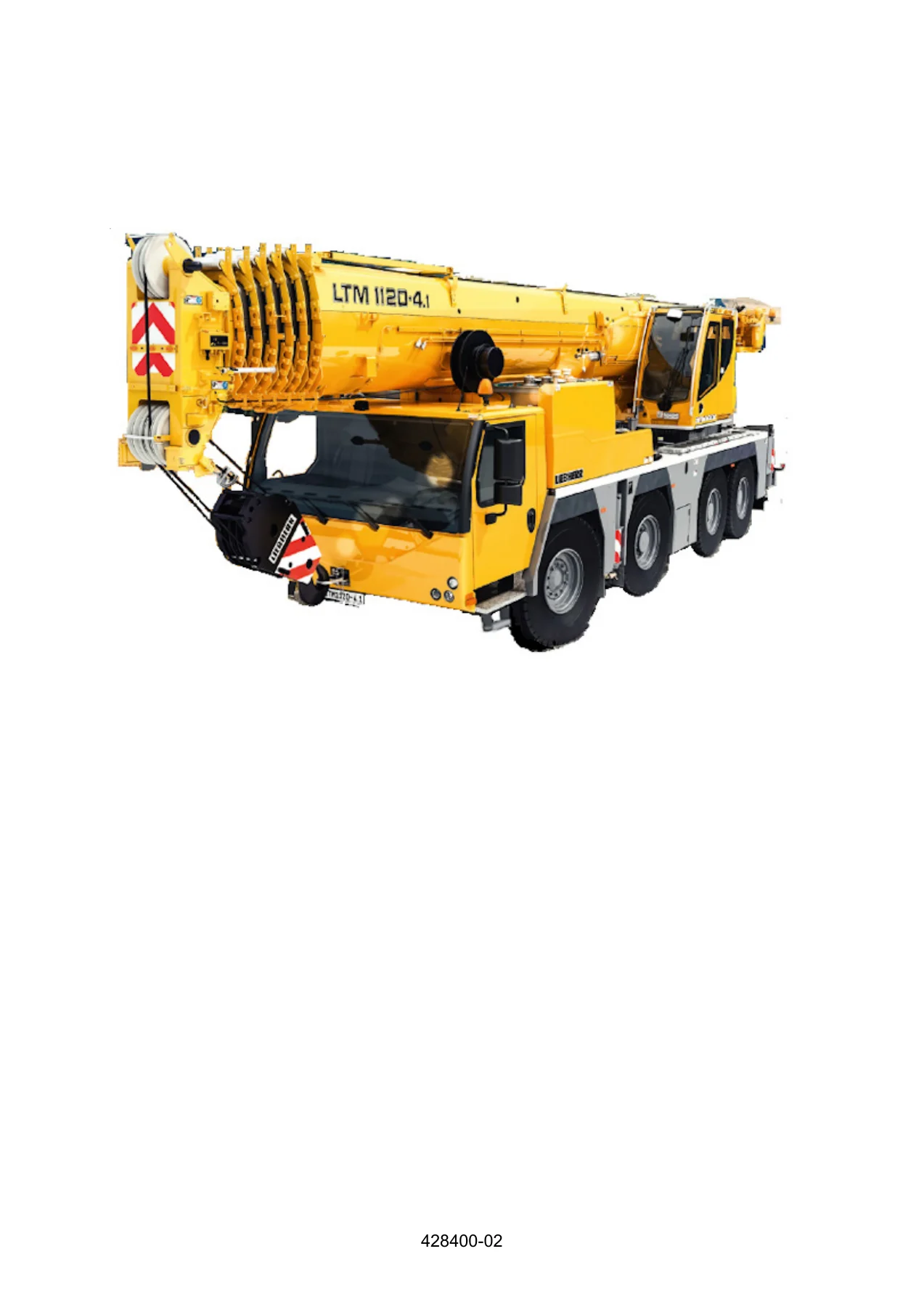
Liebherr LTM 1120-4.1 Load Chart Manual T284.007 090557 PDF
Original price was: $49.95.$29.95Current price is: $29.95.
Detailed 5,678-page load chart reference for the Liebherr LTM 1120-4.1, edition 25.01.2021, document T284.007 / 090557. Covers crane operating configurations, LICCON overload protection, boom modes, rope reeving, hook blocks, load reductions, wind calculations and extensive configuration-specific load charts.
Description
The Liebherr LTM 1120-4.1 Load Chart Manual T284.007 090557 PDF is a detailed lifting-capacity and crane-configuration reference for the LTM 1120-4.1. Edition 25.01.2021, it combines operating guidance with thousands of configuration-specific load-chart pages so the user can match the crane setup, boom arrangement, support condition, working radius, reeving, wind limit and other chart parameters before using a rated load value. The manual is focused on load-chart interpretation and crane operating configurations rather than general mechanical repair.
File Details
- Manual type: Load chart manual
- Brand / model: Liebherr LTM 1120-4.1
- Language: English
- Page count: 5,678 pages
- File format: PDF
- Document reference: T284.007
- Number: 090557
- Edition: 25.01.2021
Configuration-Specific Load Chart Reference
A major part of this Liebherr LTM 1120-4.1 load chart manual is the load-chart collection itself. The chart section is organized across 5,557 numbered chart pages and covers many combinations of boom extension, support base, counterweight or ballast condition, operating mode and permissible working range. Individual charts identify the crane as LTM 1120-4.1 — 090557 and show the information needed to interpret a particular configuration, including boom radius, telescopic boom length, rated load values, hoist-rope reeving, telescopic-section extension conditions, setup icons, slewing range and permissible wind speed.
The manual explains how to read the chart before presenting the large chart library. It defines boom radius as the horizontal distance from the hook block to the rotation axis of the crane superstructure, measured on the ground, and explains that load values are shown in tons or pounds. It also makes clear that the weight of load-lifting and fastening equipment must be deducted from the stated load value and that additional hoist-rope weight can reduce the available load when reeving differs from the chart condition. These details make the Liebherr LTM 1120-4.1 Load Chart Manual T284.007 090557 PDF more than a set of capacity tables: it also provides the rules required to interpret those tables correctly.
Understanding Setups, Icons and LICCON Data
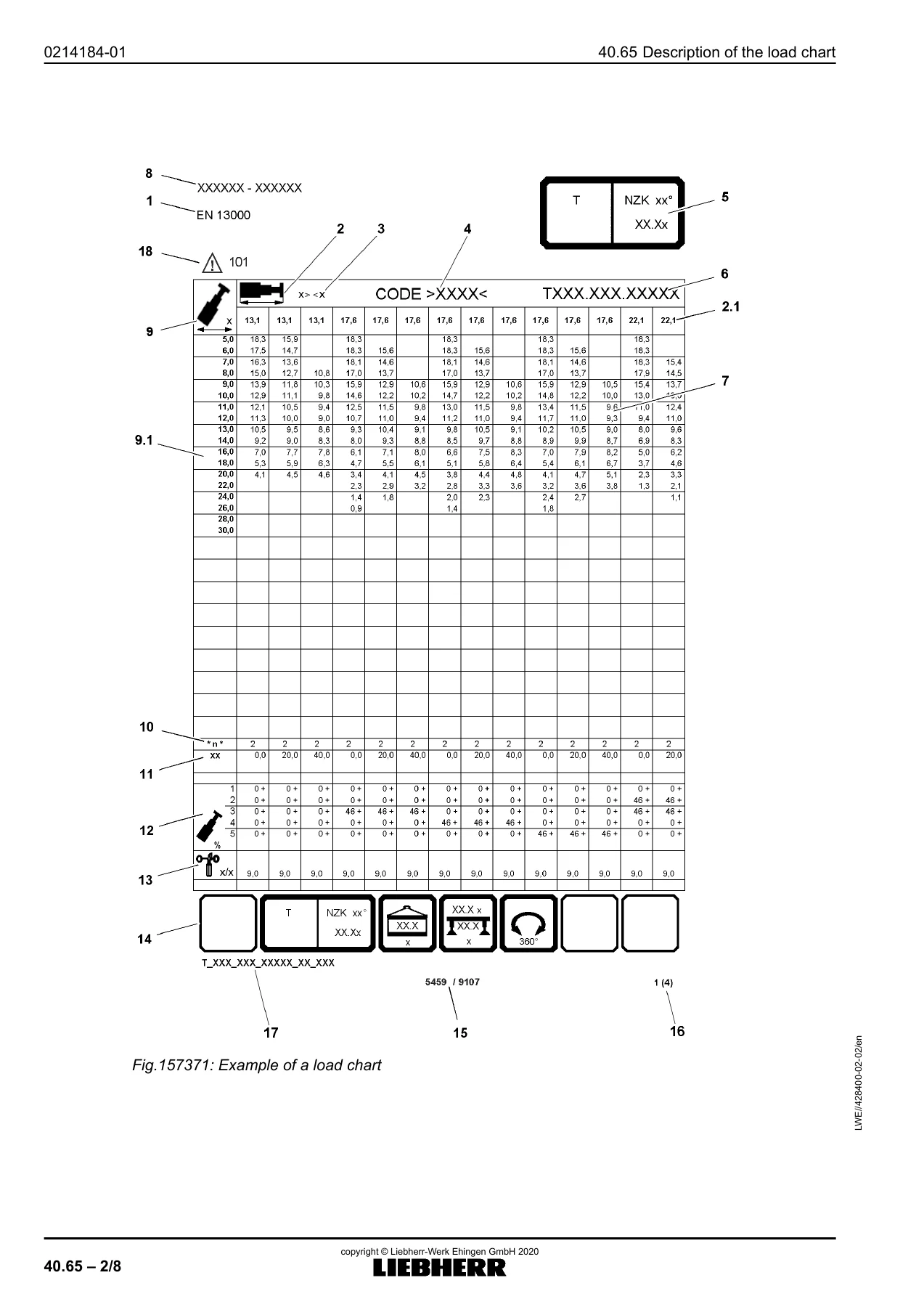
The load-chart description section breaks down the information shown on a chart, including the applicable standard, telescopic boom length, units of measure, short code, operating-mode icon, chart number, load values, crane identification, boom radius, reeving, boom angle, telescopic-section extension condition, wind speed, function-key icons, page data and codes for limitations or notes. It also explains the setup symbols used for counterweight, supported operation, variable support base, partial support arrangements, tire-supported operation and slewing ranges.
LICCON overload protection is treated as an essential part of matching the crane to the selected chart. The manual instructs the operator to set LICCON to the current setup configuration before each application and explains that the system stops hoisting and boom-luffing movement when permissible load torque is exceeded. The text also calls for checks of the overload protection, limit switches, winch speed sensor and sensors for length, angle, pressure and wind speed. Throughout the manual, the configuration selected in the crane system is tied back to the data shown in the applicable load chart.
Boom System, Rope Reeving and Hook Block Data
The boom-system material identifies the principal component-group symbols used throughout the charts: T for the telescopic boom, K for the folding jib, NZK for the hydraulically adjustable folding jib and V for the telescopic boom extension. Separate operating-mode guidance explains main-boom modes, auxiliary-boom modes, operation on the main boom with an auxiliary boom installed, maintenance operation, assembly operating modes and modes requiring an auxiliary device. This helps decode the compact operating-mode icons that appear on the chart pages.
Rope and hook-block information is unusually detailed. For the documented 19 mm hoist rope, the manual states a maximum rope pull of 74 kN (7.4 t) for Winch 1 and Winch 2. Reeving guidance explains how the maximum permissible load depends on the number of rope strands and distinguishes the 4.5-fold rope safety used with EN 13000 from the 5-fold rope safety specified by ASME B30.5 for rotation-resistant hoist ropes in applicable countries. It also explains the need to set the LICCON overload protection to the selected number of hoist-rope strands.
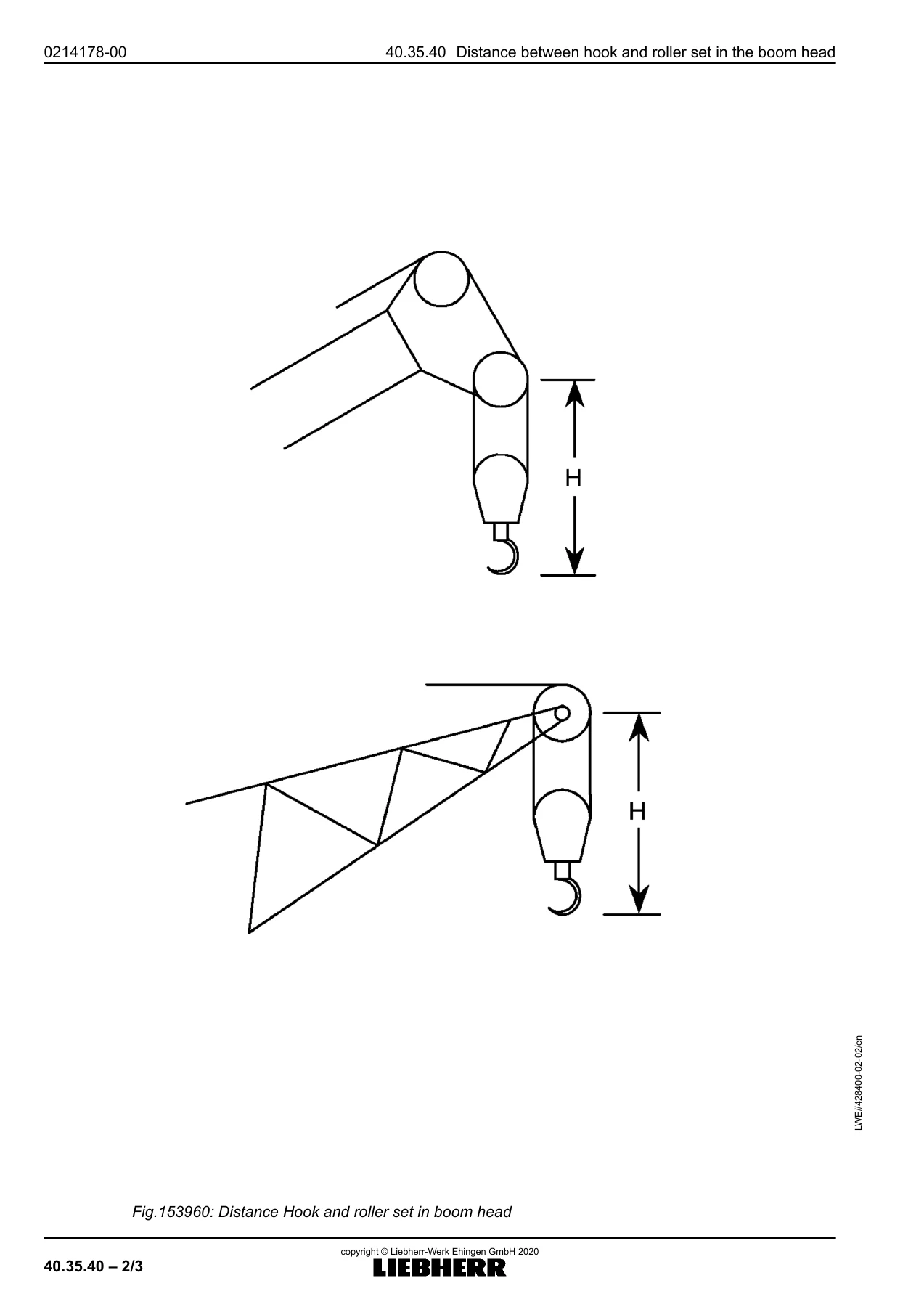
Hook-block coverage includes minimum required hook-block weight, the consequences of insufficient weight and a calculation method using G = L x M x n x F, where overall boom length, rope weight, reeving and a reeving factor determine the minimum required hook-block weight. Tables provide rope weights for multiple rope diameters and factors for reeving from 1 through 30 strands, followed by worked calculation examples. The manual also lists load hooks and hook blocks with their safe working loads, rope-pulley arrangements, maximum reeving and net weights, and provides distances between the hook and the roller set for different boom-head and folding-jib arrangements.
Load Reductions, Slewing and Special Operating Conditions
The document addresses situations where the nominal value in a basic chart needs further consideration. It explains load reductions when a boom nose is installed and when an approved folding jib is carried on the side of the boom pivot section. A separate slewing section gives maximum permissible superstructure slewing speeds at suspended nominal load for defined boom-length ranges and for specified operating modes. Assembly sections cover using the crane to disassemble or assemble front and rear sliding beams with dedicated support arrangements and working ranges.
Supported crane operation and freestanding-on-tires operation are covered separately. The supported-operation guidance addresses sliding-beam position, pinning, support plates, wheel clearance and horizontal alignment. For freestanding-on-tires operation, the manual requires a level surface, the appropriate setup configuration, specified tire pressure and axle-suspension condition, maximum permissible telescopic-boom length and controlled handling of the suspended load near the ground. The load-chart icon section also gives tire-pressure data for the tire sizes and speed symbols covered by the manual.
Wind Influence and Permissible Wind Speed
Wind receives a substantial dedicated section because it can change the stress on the crane system and affect the load indication. The manual explains the effects of wind from the rear, front and side on the boom system and LICCON overload protection. It defines projection surface, wind-resistance coefficient, wind-exposed surface, hoist load, net load, 3-second wind gust speed, dynamic pressure and wind load, then shows how these quantities are used when evaluating a lift.
The procedure distinguishes the maximum permissible wind speed shown in a load chart from a recalculated permissible speed for a specific load. A wind-exposed-surface threshold of 1.2 m²/t is used to determine when recalculation is required. Worked examples show how to calculate wind-exposed surface from projection area and wind-resistance coefficient and how to determine a revised wind limit. The manual then supplies wind-force diagrams corresponding to chart wind speeds from 7.0 m/s through 15.6 m/s. This section is especially useful when a load has a large surface area relative to its mass.
Chapters Covered
- 40.02 Basic information – Basic information and load chart manual versions
- 40.05 Crane operation – General; Crane supported; Crane freestanding on tires; Driving the crane with load
- 40.10 Utilization of the crane – Utilization of the crane and load collective
- 40.15 LICCON overload protection and limit switch – LICCON overload protection
- 40.20 Telescopic boom – Telescopic boom operating limits and telescoping under partial load where permitted
- 40.25 Rope winches – Rope pull
- 40.30 Hoist rope reevings – Hoist rope reeving chart; reeving guidance; 5-fold rope safety according to ASME B30.5
- 40.35 Hook blocks and load hooks – Minimum required hook-block weight; calculation method; procedure in case of slack rope
- 40.35.10 Hook blocks for single operation – Crane operation with 1 hoist rope F=74 kN and d=19 mm
- 40.35.40 Distance between hook and roller set in the boom head – Hook-to-roller-set distance data
- 40.50 Load reductions – Installed boom nose; installed folding jib
- 40.55 Slewing speed of the crane superstructure – Maximum permissible slewing speed at suspended nominal load
- 40.60 Boom system – Component groups and combinations for operating modes
- 40.62 Operating modes – Main boom; auxiliary boom; main-boom operation with installed auxiliary boom
- 40.62.10 Special operating modes – Maintenance operation
- 40.62.20 Assembly operating modes – Front and rear sliding-beam assembly and disassembly with the crane
- 40.62.30 Operating modes with auxiliary device – Auxiliary-device operating mode
- 40.65 Description of the load chart – Chart description and icon explanation
- 40.70 Wind influences for crane operation – Terminology; effect on LICCON overload protection; permissible wind speed and wind-surface calculation
- 40.90 Load charts – Configuration-specific load charts
Taken together, these chapters connect the raw chart values with the crane setup that makes each value valid. The manual helps the user move from operating-mode identification and support condition to boom geometry, reeving, wind constraints and finally the applicable capacity table, while also documenting the limitations and deductions that must be observed around the rated values.
Get the Liebherr LTM 1120-4.1 Load Chart Manual T284.007 090557 PDF
Use the Liebherr LTM 1120-4.1 Load Chart Manual T284.007 090557 PDF to check configuration-specific lifting data, interpret load-chart symbols, confirm boom and support conditions, select the required reeving, evaluate hook-block requirements, account for wind influence and review the operating limitations that accompany the charts. Correct setup data and chart interpretation matter because a rated value is only valid for the configuration, radius, boom condition, working range and other conditions stated for that chart. This digital manual is delivered as an instant PDF after purchase, with no shipping delay. Open it on your computer, tablet or phone, and print the pages you need for convenient reference.
IMAGES PREVIEW
Reviews
There are no reviews yet.