
Liebherr LTM LTF LG LTR Diagnostics Operating Instructions 99900-07-02 PDF
Original price was: $79.95.$49.95Current price is: $49.95.
Liebherr LTM, LTF, LG, LTR crane diagnostics operating instructions BAL-No. 99900-07-02 in PDF. Covers LICCON errors, LSB bus systems, Multi-CPU test system, remote diagnostics and more.
Description
Liebherr LTM LTF LG LTR Diagnostics Operating Instructions 99900-07-02
This Liebherr LTM LTF LG LTR Diagnostics Operating Instructions 99900-07-02 is the diagnostic and troubleshooting guide for Liebherr mobile crane families covered in the document. It is a 242-page PDF written in English, issued under BAL-No.: 99900-07-02, and is intended for technicians working with the LICCON computer system, LIEBHERR-System-Bus (LSB), CAN-connected components, and the diagnostic test routines used across LTM, LTF, LG, and LTR cranes.
File Details
- Manual type: Diagnostics Operating Instructions
- Brand: Liebherr
- Model coverage: LTM, LTF, LG, LTR crane series
- Document number: BAL-No.: 99900-07-02
- Language: English
- Page count: 242 PDF pages
- File format: PDF
Chapters Covered
- 20.00 Diagnostics
- 20.01 Bus system overview
- 20.05 Error identification – LICCON computer system
- 20.10 Test system
- 20.15 Remote diagnostics
- 20.20 Diagnostics – Disk brake pads
- 20.25 Trailing axle diagnostics
- 20.30 Test system, TY-guying
20.00 Diagnostics
The opening diagnostics section sets the structure for the rest of the manual. It introduces the diagnostic workflow used across the covered Liebherr crane families and explains how the following chapters are organized for fault finding.
20.01 Bus system overview
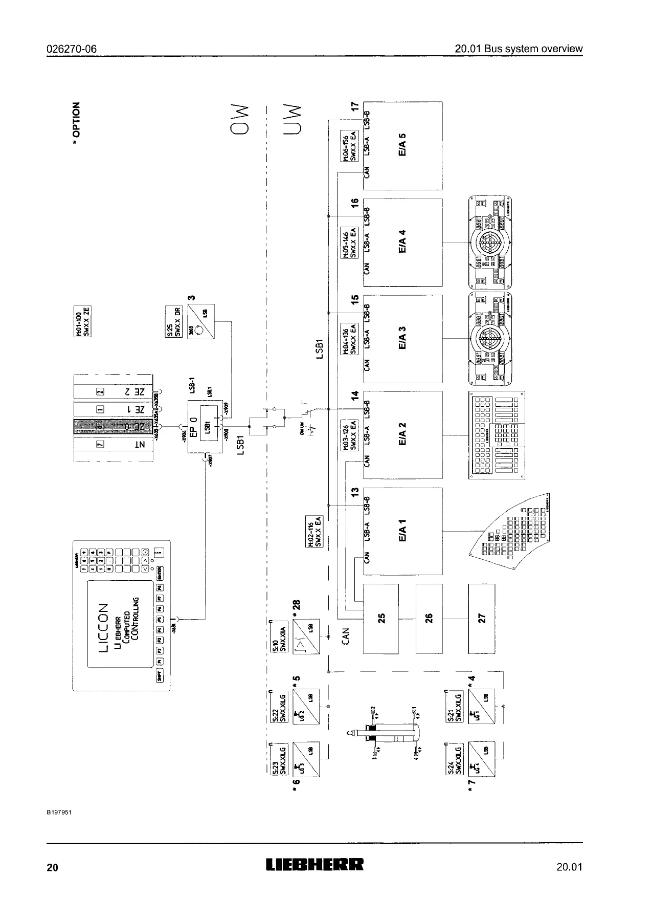
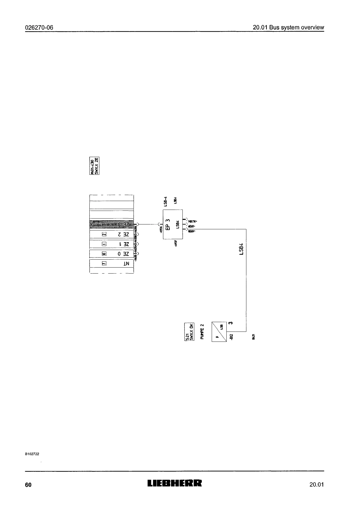
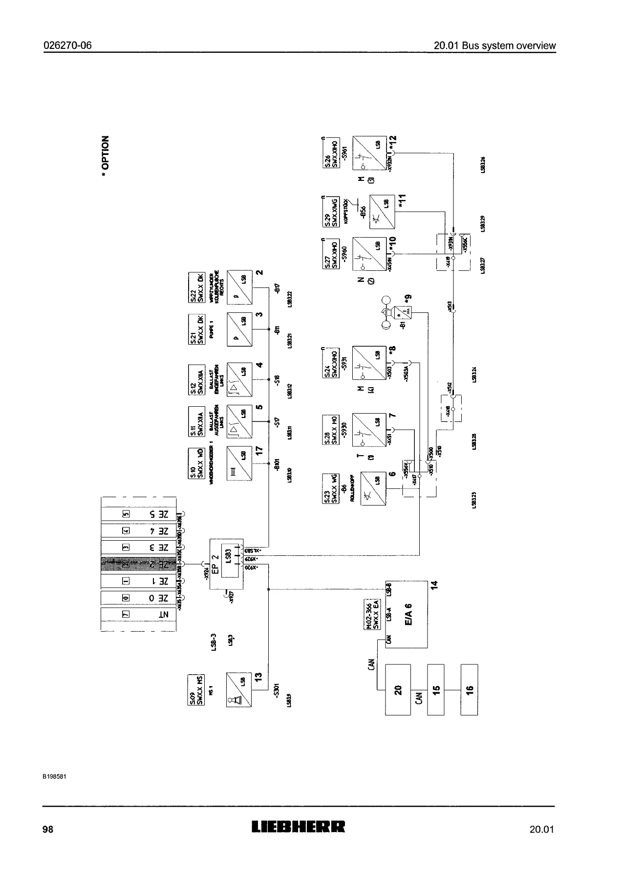
This is the largest reference chapter. It provides LSB1, LSB2, LSB3, LSB4, LSB5, and LSB6 overviews for specific crane variants including LTF1035-3.1, LTF1045-4.1, LTM1040-2.1, LTM1070-4.1, LTM1090-4.1, LTM1095-5.1, LTM1100-5.2, LTM1130-5.1, LTM1150-5.2, LTM1160-5.1, LTM1200-5.1, LTM1220-5.1, LTM1220-5.2, LTM1400-7.1, LTM1500-8.1, LG1750, and LTR1100. Each overview lists the stations, bus addresses, CPUs, IPCBs/EPs, monitors, sensors, pressure sensors, length/angle sensors, input/output modules, and CAN components assigned to the LSB. The diagrams show how the bus architecture differs between crane sizes and equipment levels.
20.05 Error identification – LICCON computer system
This chapter explains how LICCON errors are classified and displayed. It covers monitor errors, basic module errors, unique power unit errors, initialization errors, system errors, fatal system errors, application errors, and operating errors. It documents the LICCON-Error-Code (LEC) structure, including error class, device, error path, and error type, with examples such as E. 02 0266 and B. 4 9 9 8 9 8. It also includes LED error codes and status displays on I/O modules, error display procedures in the superstructure and chassis, and the separate error list format with plug, sheet, class, and priority columns. Procedures for checking the power unit and central processing unit are included, along with dismounting and fitting instructions.
20.10 Test system
The Multi-CPU test system chapter describes the diagnostic tool used to locate LSB component malfunctions. It explains starting the test system in CRANE OPERATION or TEST SYSTEM mode, selecting a CPU or group, reading hardware errors, calling up LSB overviews, and using graphic and documentary LSB displays. Master and slave detail displays are covered for I/O modules, CPUs, hoist limit switches with winch sensors, angle sensors, length sensors, inductive analog sensors, and tension measuring lugs. The chapter also documents the procedure for LSB sensor programming.
20.15 Remote diagnostics
This section covers remote diagnostics via the GSM module. It explains what happens when remote diagnostics is started, how the LIEBHERR customer service employee can service the LICCON test system through a PC connection, and the safety precautions required while the screen is frozen. It notes that the system can identify static electrical errors scanned in a time reference greater than 2 seconds, and includes troubleshooting for failed data connections.
20.20 Diagnostics – Disk brake pads
This chapter provides diagnostics for disk brake pads using the diagnostics plug -X98 70 in the center console. It explains how to check each brake pad individually with a multimeter, interpret 24 V and 0 V signals, and identify worn brake pads or electrical problems in the diagnostics circuit.
20.25 Trailing axle diagnostics
Trailing axle diagnostics are covered through the blinker code issued on the control light. The chapter explains that a blinker code is issued after ignition is turned on, with the buzzer sounding three times, and that the code corresponds to the LICCON Error Code (LEC). It includes the configuration and evaluation of the blinker code, with an example LEC 3 9 4 2 1 5 broken into device, error path, and error type.
20.30 Test system, TY-guying
The final chapter covers the TY test system for TY-guying. It states that the operating interface and test system cannot be observed simultaneously on this crane, and that the TY test system is intended for remote diagnostics by authorized specialist personnel. It includes the safety warning that crane operators and crane personnel must not operate the TY test system for diagnostic purposes.
Why This Liebherr Diagnostic Manual Matters
Diagnosing a modern Liebherr crane without the correct bus overviews and error code definitions is slow and risky. This manual gives you the exact LSB station assignments, LICCON error classes, test system screens, and diagnostic procedures needed to trace faults across the chassis and superstructure. Whether you are dealing with a monitor error, a power unit fault, an initialization error, a system error, an application error, or a trailing axle blinker code, the manual shows where to look and how the system reports the problem.
For workshops, fleet maintenance teams, and technicians who support LTM, LTF, LG, and LTR cranes, this PDF is a practical diagnostic companion. It helps reduce guesswork, avoid unnecessary component replacement, and follow the manufacturer’s diagnostic sequence for the LICCON computer system and LIEBHERR-System-Bus. The bus system overviews alone are invaluable when you need to confirm addresses, identify missing stations, or understand how modules are distributed across LSB1 through LSB6.
IMAGES PREVIEW
Delivery is instant. After payment, the Liebherr LTM LTF LG LTR Diagnostics Operating Instructions 99900-07-02 is available as a PDF download with no shipping and no waiting. You can open it on a laptop, tablet, or phone in the workshop, print the pages you need, and keep the complete diagnostic reference with your service documentation. This is the complete 242-page diagnostic operating instructions file for the covered Liebherr crane families, ready for immediate use.
Reviews
There are no reviews yet.