Linde Electric Lift Truck 324 02 Series With Ldc E12 E15 E16 Service Training Manual – DOWNLOAD
Original price was: $21.95.$14.95Current price is: $14.95.
Linde Electric Lift Truck 324 02 Series With Ldc E12 E15 E16 Service Training Manual
Description
Linde Electric Lift Truck 324 02 Series With Ldc E12 E15 E16 Service Training Manual
LINDE ELECTRIC LIFT TRUCK 324 02 SERIES WITH LDC E12 E15 E16 SERVICE TRAINING MANUAL – DOWNLOAD:
IMAGES PREVIEW OF THE MANUAL:
TABLE OF CONTENTS:
Linde Electric Lift Truck 324 02 Series With Ldc E12 E15 E16 Service Training Manual
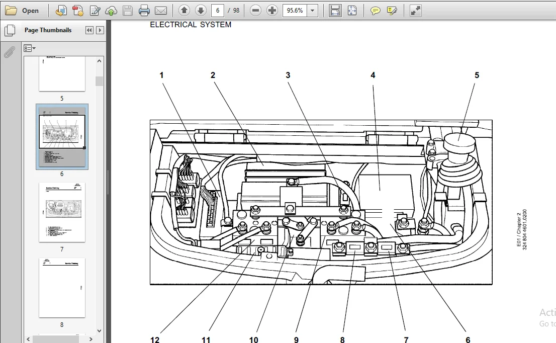
Electrical system
Traction controller
Current path for forward travel direction
Current path for reverse travel direction
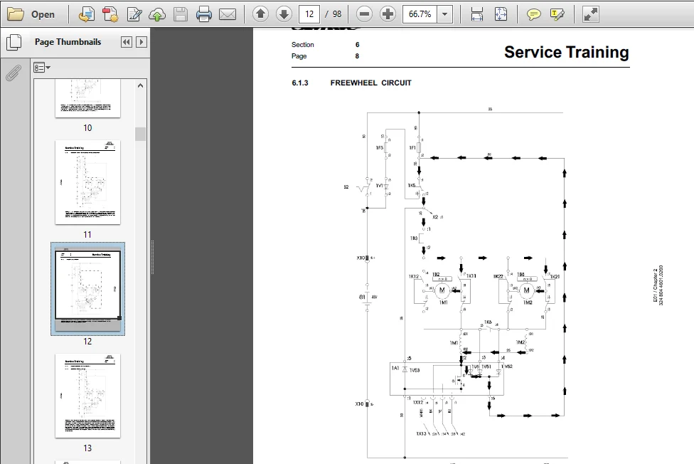
Freewheel circuit
Regen braking on 48V trucks
Braking circuit stage 1
Braking circuit stage 2
Braking circuit stage 3
Electronic Traction Controller
Power supply
Truck encoding
Traction enable via the seat switch
Control of directional contactors
Forward direction of travel
Reverse direction of travel
Single-pedal models
Modification to singlepedal model
Turning
Handbrake current
Regenerative braking on 48V trucks
Speed sensor in the traction motor
Actual current sensor
General explanation
Truck diagnostics
Window 1 Truck status data
Window 2 information and error codes
Window 3 Fault history
Window 31 Confirming fault history
Window 32 Clearing entire fault history (master version only)
Window 4 Digital inputs
Window 5 Digital outputs
Window 6 Analogue signals
Wndow 7 setting truck parameters
Window 71 Setting parameters in window 7 to default settings
Window 72 Setting special truck parameters (master version only)
Window 73 Default parameters of windows 7 and 72
Window 74 Special version parameters
Pulse control for the working hydraulics
Lift electronics
Power supply
Enable signal, temperature switch and speed reduction with discharged battery
Control of the various work functions
Sensos in the control valve block
Adjustments
Steering controlLER
Functional description
Composite instrument
Brush wear indicator
Traction motor overheating
Hour meter
Service interval indicator
Service interval time
Battery discharge indicator
Operation of diagnostic unit together with composite instrument
Wiring diagram
Wiring diagram 24V trucks
Wiring diagram 48V trucks
Hydraulic system
Hydraulic pump motor
Hydraulic pump motor 24V
Hydraulic pump motor 48V
Changing the hydraulic pump motor brushes
Removal and installation of the hydraulic pump motor
Control valve
Removing the control valve
Adjusting the pressure relief valve
Distance sensor
Working and steering hydraulics circuit diagram
FILE FORMAT:
LANGUAGE:ENGLISH
PAGES:98
DOWNLOADABLE:YES
FILE TYPE:PDF
PLEASE NOTE:
- This is the same manual used by the dealers to diagnose and troubleshoot your vehicle
- You will be directed to the download page as soon as the purchase is completed. The whole payment and downloading process will take anywhere between 2-5 minutes
- Need any other service / repair / parts manual, please feel free to contact [email protected] . We still have 50,000 manuals unlisted
Dallas Kannon –
The download was fast and the quality is great. This is what I have been needing