Link-belt 80 Spin Ace Tier III Service Manual – PDF DOWNLOAD
$32.95
Link-belt 80 Spin Ace Tier III Service Manual – PDF DOWNLOAD
Description
Link-belt 80 Spin Ace Tier III Service Manual – PDF DOWNLOAD
FILE DETAILS:
Link-belt 80 Spin Ace Tier III Service Manual – PDF DOWNLOAD
Language : English
Pages : 753
Downloadable : Yes
File Type : PDF
IMAGES PREVIEW OF THE MANUAL:
DESCRIPTION:
Link-belt 80 Spin Ace Tier III Service Manual – PDF DOWNLOAD
Safety
[1] Before starting maintenance work, read carefully and fully understand materials (instruction manual and maintenance manual).
[2] Before disassembling and assembling, take sufficient safety measures to prevent accidents such as falling loads, being caught in or under the machine and burns. When working under the machine, use safety blocks to support the machine to avoid workers getting caught.
[3] Cranes and other hoist equipment must be operated by licensed operators.
1) Crane operators and slinging workers must be licensed.
2) Make sure to inspect rigging.
[4] Wear proper clothing and protective gear as necessary during inspection or maintenance (safety shoes, helmets, protective goggles, gloves, earplugs, dust mask and other protective devices).
[5] Always keep the work area clean to avoid accidents such as skidding during travel and falling objects.
[6] Make sure to ventilate properly when inspecting or servicing a machine indoors.
[7] Be prepared for any emergencies and take necessary fire preventative measures
Introduction
- Appropriate operations, maintenance, inspections, troubleshooting, and repair of the machine are vital
to keep it performing at its best and for the longest possible period of time, and to prevent it from breaking
down. - This document includes a General Outline, Specifications (Performance), Troubleshooting and Disassembly/
maintenance instructions, which are necessary for inspection, troubleshooting and repair of the
machine.
(Note: This Shop Manual is to be filed with the additional information to be added later.) - For details of the engine, refer to the maintenance manual published by the engine manufacturer.
- For daily inspections and maintenance, see the Operator’s Manual to take advantage of the machine’s
full performance. - Numerical values or others may be changed without notice due to design alterations or other reasons.
TABLE OF CONTENTS:
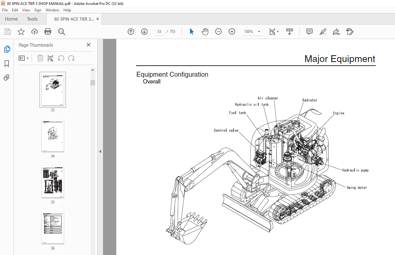
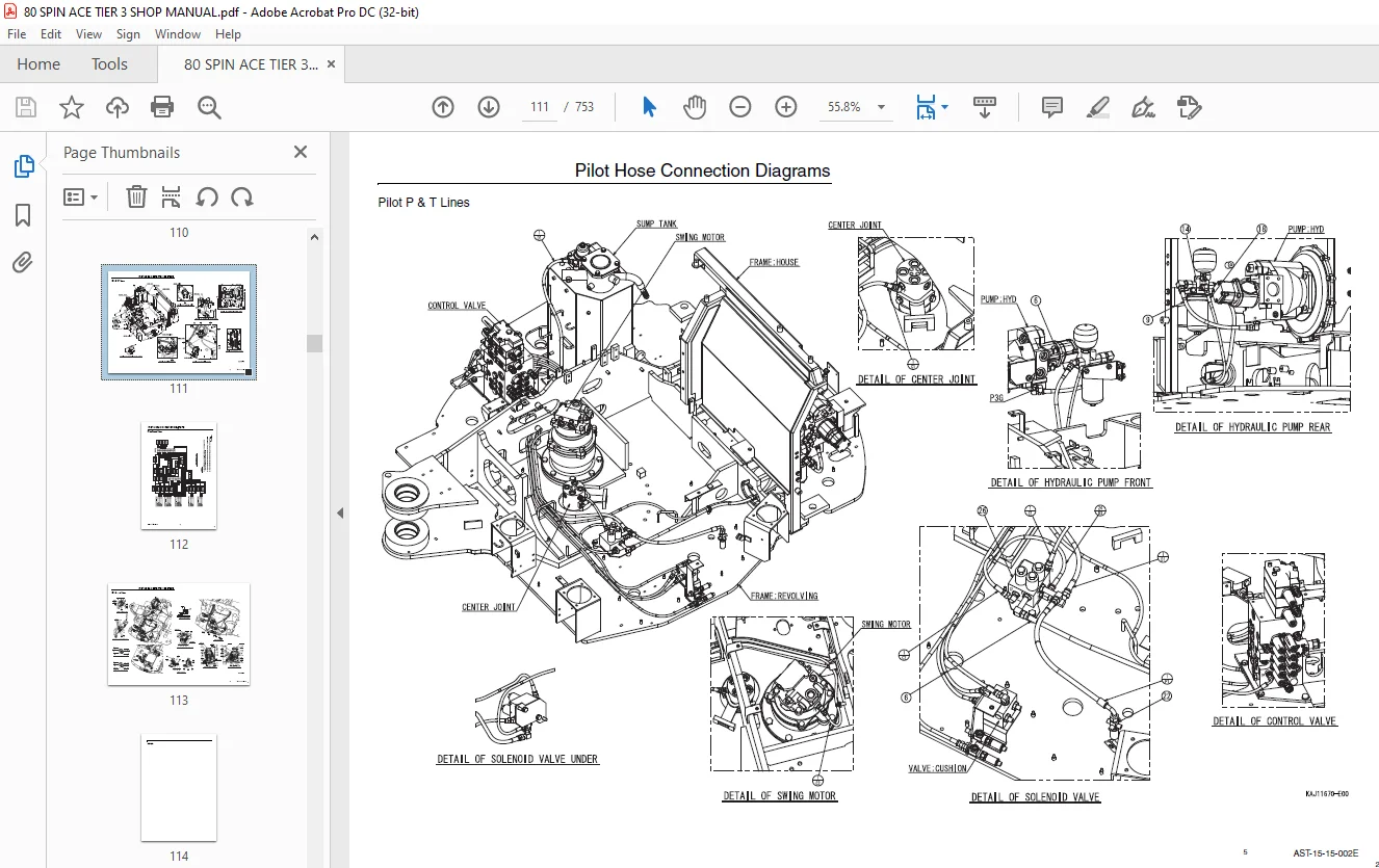
Main body Section
Specifications 1
Overall 1
1 Main Data 1
2 Performance 1
3 Main Body Dimensions 1
4 Engine 2
5 Cooling System 2
6 Upper Side Work System 3
7 Operating Device 4
8 Swing Units 5
9 Travel Lower Body 5
10 Dozer Blade 5
Hydraulic Equipment 6
1 Hydraulic Device 6
2 Control Valve, Cylinder 6
Capacities, Filters 7
1 Coolant and Oil Capacities 7
2 Hydraulic Oil Filters 7
3 Fuel Filter 7
Overall View 8
4 Overall View (80) 8
5 Standard Arm (1 71 m) 8
6 Long Arm (2 12 m) 8
Work Range Diagram 9
Work Range Diagram (80) 9
1 Standard Arm (1 71 m) 9
2 Long Arm (2 12 m) 10
Optional Components 11
List of Optional Components 11
Major Equipment 12
Equipment Configuration 12
1 Overall 12
2 Operator’s Cab 13
Main Equipment Table 14
Lower Mechanism 14
Assembly Diagrams (with blade) 14
Lower Component 15
1 Travel Unit 15
2 Take-up Roller 15
3 Upper-roller 15
4 Lower-roller 15
5 Recoil Spring 16
6 Shoes 16
Upper Component 17
1 Swing Unit 17
Engine-related 18
1 Engine 18
2 Muffler 18
3 Air Cleaner (double element) 19
4 Radiator 19
Hydraulic Device 20
1 Hydraulic pump 20
Control-related 21
1 Control Valve 21
2 Solenoid Valve (4 stack) 21
3 Remote Control Valve (left/right, travel operations) 22
4 Remote Control Valve Characteristic Diagram 24
5 Center Joint 26
Backhoe Attachment 27
1 Cylinder 27
2 Attachments 28
Fuel Tank 29
Sump Tank 31
Hydraulic Section
Hydraulic Pump Operational Description 1
Configuration and Principle of Operation 1
Flow Control 3
1 Constant controlling of simultaneous output 3
2 Power-down control by discharge pressure of blade pump (blade shift) 4
Control Valve Operation 5
Operation with All Spools in Neutral 5
1 Main passage 5
2 Signal passage 5
Independent Operation 7
1 Travel spool switch-over (Figure 1) 7
2 Backup spool switch-over (Figure 2) 7
3 Swing spool switch-over (Figure 3) 8
4 Bucket spool switch-over (Figure 3) 8
5 Boom spool switch-over 9
6 Arm spool switch-over 11
7 Blade spool switch-over (Add-on) (Figure 9) 13
8 Boom Swing spool switch-over (Add-on) (Figure 9A) 13
9 Relief valve 14
10 Anti-drift valve (Boom section) 15
Combined Operations 17
1 Additional operation with travel (Figure 14) 17
Relief Valve 18
1 Main relief valve 18
2 Overload relief valve 19
Swing Unit Swing Motor 20
Functional and Operational Description 20
Swash Plate Motor 20
Parking Brake (for models equipped with parking brakes) 22
Principle of Relief Valve Operation 23
Makeup Valve 26
Reduction Gear (2-stage planetary gear) 27
Overview 28
1 Features 28
2 Operational Description 28
Travel Unit Travel Motor 32
External Dimensional Drawing 32
Basic Structure and Drawings 33
1 Basic structure of GM motor 33
2 Parts list 35
Operational Description 36
1 Reduction gear 36
2 Hydraulic drive section 37
Hydraulic Circuit Section
Port Locations 1
Hydraulic Pump 1
Control Valve 2
Control Valve 3
Pilot Hose Connection Diagrams 4
Pilot P & T Lines 4
Pilot Control Lines 6
Functional Description 8
List of Functions 8
Control Valve Configuration Table 10
Overview 10
Explanation of Hydraulic Circuit and Operations (standard model) 11
Travel Circuits 11
High-speed Travel Circuit 11
Low-speed Travel Circuit 13
Straight-travel Circuit (Boom-Up and Travel-Forward) 15
Swing Circuit 17
Swing Parking Circuit 17
Swing Override Throttle Circuit 19
Bucket Circuit 21
Bucket-Opening Circuit 21
Arm CIrcuits 23
Arm-in / Arm-out 2-speed Circuit 23
Boom Circuits 25
Boom Circuit 1: Boom-up 2-speed Circuit 25
Boom Circuit 2: Boom-down Load Holding Valve Circuit 27
Boom Swing CIrcuit 29
Boom Swing CIrcuit 29
Blade Circuits 31
Blade Circuits 31
Explanation of Hydraulic Circuit and Operations (option) 33
Backup Circuits 33
Breaker and Crusher Circuit (2-speed confluence crusher circuit) 33
Breaker and Crusher Circuit (breaker circuit)
Ultra Small Tail Swing Hydraulic Excavator 36
Backup Reciprocating Circuit (ultra small swing hydraulic excavator) 38
Secondary Backup Reciprocating Circuit
(ultra small tail swing hydraulic excavator) 40
Electric Circuits Section
Operational Description 1
Monitor Display 1
1 Monitor switch panel 1
2 List of Functions 2
Engine Control 3
1 Engine start-up control 3
2 Engine Start-up Circuit 4
3 Monitor Output Control 10
4 Monitor Display Control 17
Electric Circuit Diagrams 23
Electric Circuit Diagram 1 23
Electric Circuit Diagram 2 24
Electric Circuit Diagram: Air Conditioner 1 25
Electric Circuit Diagram: Air Conditioner 2 26
Harness Diagrams 27
Upper Frame 27
Frame Wiring Main Harness 27
Inside Cab 28
Cab Wiring Main Harness 28
Wiring Diagrams 29
Electrical Components and Wiring for Upper Frame (frame) 29
Electrical Components and Wiring for Cab 30
Electrical Components and Wiring for Upper Frame (engine) 31
Electrical Components and Wiring for Upper Frame (battery) 32
Heater 33
Air Conditioner 34
Inside Frame 34
Inside Cab 35
Maintenanse section
Measuring / Adjusting Pressure 1
Measuring Pressure 1
1 Basic conditions 1
2 Pressure settings 1
3 Ports for measuring pressure 2
4 Preparation for Measuring Pressure 3
5 Measuring Pressure 4
Pressure adjustment 7
1 Pressure adjusting points 7
Bleeding Air 9
Attachments Dimensions 10
Attachment Installation Methods 10
Appendix 11
Unit Conversion Table 11
New Hydraulic Oil 12
Long-life hydraulic oil (IDEMITSU Daphne Super Hydro 46SX) 12
Compatibility 13
List of Common Features and Compatibility of Major Parts 13
Questions? Email us: [email protected]
https://vimeo.com/891789847?share=copy
S.S