Linkbelt 240X2-MH Shop Manual 2321 – PDF DOWNLOAD
Original price was: $75.95.$33.95Current price is: $33.95.
Linkbelt 240X2-MH Shop Manual 2321 – PDF DOWNLOAD
Description
Linkbelt 240X2-MH Shop Manual 2321 – PDF DOWNLOAD
FILE DETAILS:
Linkbelt 240X2-MH Shop Manual 2321 – PDF DOWNLOAD
Language : English
Pages : 1326
Downloadable : Yes
File Type : PDF
Size: 92.5 MB
IMAGES PREVIEW OF THE MANUAL:
Contact us: [email protected]
https://vimeo.com/770601069
TABLE OF CONTENTS:
Linkbelt 240X2-MH Shop Manual 2321 – PDF DOWNLOAD
Overall
Main Data 1
Performance 1
Complete Machine Dimensions 1
Main Unit Dimensions 2
Engine 2
Hydraulic Device 3
Control Valve 3
Cooling System 3
Operating Device 4
Swing Units 5
Travel Lower Body 5
Work Unit 5
Hydraulic Cylinder 6
Coolant and Oil Capacities 6
Hydraulic Oil Filter 6
Overall View
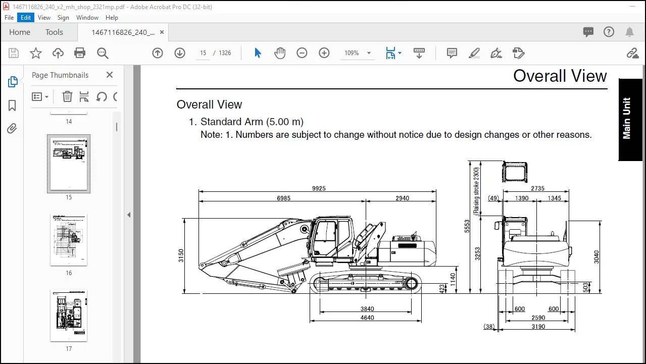
Overall View
Standard Arm (5 00 m) 7
Work Range Diagram
Work Range Diagram
Standard Arm (5 00 m) 8
The first 7 sections of this manual
cover the parts of the MH that are
different from the standard 240 X2
Page 186 starts the standard 240 X2
Hydraulic
Hydraulic Equipment Layout
Overall View 1
Pump Chamber Hydraulic Equipment Layout 2
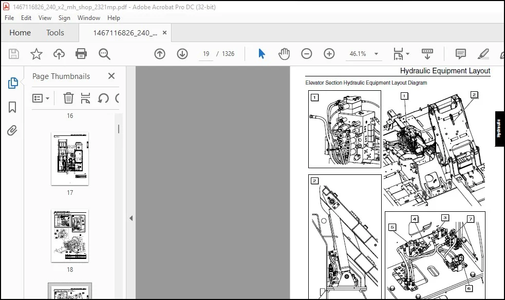
Elevator Section Hydraulic Equipment Layout Diagram 3
Dynamo-related Hydraulic Equipment Layout Diagram
(for Japan and North America) 4
Port Diagrams
Pump
1 Hydraulic Pump 5
Valves
1 Control Valve 6
2 Solenoid Valve for Elevator Emergency Lowering 7
3 Elevator Control Solenoid Valve 7
4 Reducing Valve (for interference prevention)
(for Japan, North America, general export) 8
5 Check Valve 8
Manifolds
1 Elevator Control Manifold 9
2 Manifold for Mode Switchover Solenoid Valve 9
Pilot Hose Connection Diagram
Pilot P and T Lines 10
Pilot Control Line (cab/frame) 14
Pilot Control Line (cab) 16
Pilot Control Line (frame) 18
Pilot Control Line (2-way selector valve) 20
Pilot Control Line (4-way selector valve) (for Japan) 24
Function List
Function Table 29
Control Milli-amp List
Control Milli-amp 31
Magnet Circuit
Magnet Circuit (for Japan, North America) 32
Elevator Circuit
Elevator Circuit 34
Option Circuits
2nd Option Circuit 36
2 Pumps Flow Circuit 38
Main Equipment Structure and Operation Explanation
Pump
1 Hydraulic Pump 41
(1) Structure and operation principles 41
(2) Hydraulic pump internal structure diagram 42
2 Gear Pump 44
(1) Gear pump internal structure diagram 44
(2) Explanations of structures and operations 44
Electrical
Electrical Equipment Layout Diagram
Overall View 1
1 Main Unit Right Side Layout Diagram (pump chamber) 2
2 Electrical Parts and Wiring (cab) 3
3 Electrical Parts and Wiring (interference prevention)
(for Japan, North America, general export) 4
4 Power Supply Unit: Lifting Magnet (for Japan, North America) 5
Stand Alone Parts Diagram 6
Electrical Connectors Wiring Diagram
Main Frame 8
1 Main Frame 8
Cab
1 Cab Main Harness 10
2 Cab Sub-harness 12
Console
1 Console Right Harness 14
2 Console Left Harness 15
Interference Prevention (cab) (for Japan, North America, general export)
1 Interference Prevention (cab) 16
Connector Installation Fitting (for Japan, North America) 17
Electrical Parts and Wiring Assembly Diagram
Main Frame 18
Cab 20
Interference Prevention (for Japan, North America, general export) 22
Lifting Magnet (for Japan, North America) 24
Explanation of Functions and Operations
Electrical Function List 26
Engine Speed Control 27
1 Characteristics (during magnet mode) (for North America) 27
2 Idling Control (auto/one-touch) (for Japan, North America) 28
Pump Control
1 Pump Horsepower Boost Control 30
Operation Explanation
Magnet Control Circuit (for Japan, North America) 31
1 Operation Flow 31
2 Magnet Control Circuit (for Japan, North America) 32
Service Support
Screen Display List 33
1 Model Setting 33
Maintenance
Pressure Measurement and Adjustment Procedures
Pressure Measuring Ports 1
Pressure Measurement and Adjustment Procedures 2
1 Main Pressure Measurement 2
2 Pilot Pressure Measurement 4
3 Negative Control Pressure Measurement 5
Power Generation Line, Elevator 6
2nd option pressure measurement 6
A Dynamo motor pressure measurement (for North America) 7
B Elevator cab pressure measurement (2nd option pressure measurement) 7
Dynamo Motor Line Relief Pressure Adjustment
(for Japan, North America) 8
Hydraulic Pump Flow Measurement Procedures
Preparations 9
Work Preparations 10
Air Bleed Procedures
Hydraulic Pump 13
Interference Prevention Device
Functions
System Function 1
Interference Prevention System Operation 2
Temporary Cancellation Function 3
Handling Abnormalities 4
Circuit Explanations
Boom (up) Interference Prevention Function 5
Elevator Cab Interference Prevention Function 7
Arm (in) Interference Prevention Function 9
Temporary Cancellation Function 11
Handling Abnormalities (shut-off function) 13
Handling Abnormalities (redundancy function) 15
Setting Method
Default Settings Method 17
Settings Confirmation
Operation Confirmation for Cab Interference Prevention Function 19
Operation Confirmation of Emergency Cancellation 22
Troubleshooting
Abnormality Display 23
1 Angle Sensor Troubleshooting 25
2 Proportional Valve Troubleshooting 26
3 Abnormal Proximity Troubleshooting 27
Measurement Jigs for Interference Prevention 28
1
Contents
Lifting Magnet
Operator’s Manual
Introduction 1
Important Safety Items 2
1 Safety 3
2 Specifications
2-1 Magnet Specifications Machine Summary 6
3 Operating Methods
3-1 Operation Switches and Magnet Operation 7
3-2 Actual Operation 7
3-3 Cautions during Operation 9
3-4 Cautions during Cleaning 10
4 Inspection
4-1 Daily Inspection – (inspection before starting operation) 11
4-2 Periodic Inspection 12
5 Monitor (touch panel) Layered Structure
5-1 Monitor (touch panel) Layered Structure 14
6 Monitor (touch panel) Operation Method 15
Magnet mode 15
Contents
1
Lifting Magnet
Maintenance Manual
1 Magnet Device 2
2 Electrical Schematic Diagram 3
3 Dynamo
3-1 Dynamo Specifications 4
3-2 Dynamo Structure 4
3-3 Dynamo Component Parts 4
4 Control Board
4-1 Layout of Control Board Component Equipment 5
4-2 Control Board Component Equipment 6
4-3 Control Board Schematic Diagram (1) 7
4-4 Control Board Schematic Diagram (2) 8
4-5 Control Board Schematic Diagram (3) 9
5 Inspection 10
6 Monitor (touch panel) Layered Structure 11
7 Monitor (touch panel) Operating Methods
Maintenance mode 13
8 Troubleshooting
8-1 Attention and Warning Function Table 18
8-2 Response When Attention Trouble Occurs 18
8-3 Response to Trouble When Warning Trouble Occurs 21
9 Investigation of Causes of Load-side Abnormalities 22
10 IGBT Module Abnormality Judgment 23
11 Investigation of Causes of Abnormalities with
Dynamo Output Voltage 24
12 Basic Settings 26
13 Operation Method Settings 31
PLEASE NOTE:
- This is the SAME manual used by the dealers to troubleshoot any faults in your vehicle. This can be yours in 2 minutes after the payment is made.
- Contact us at [email protected] should you have any queries before your purchase or that you need any other service / repair / parts operators manual.
S.V