Linkbelt 470X3 A3 Assembly Diagrams Service Manual – PDF DOWNLOAD
Original price was: $75.95.$33.95Current price is: $33.95.
Linkbelt 470X3 A3 Assembly Diagrams Service Manual – PDF DOWNLOAD
Description
Linkbelt 470X3 A3 Assembly Diagrams Service Manual – PDF DOWNLOAD
FILE DETAILS:
Linkbelt 470X3 A3 Assembly Diagrams Service Manual – PDF DOWNLOAD
Language : English
Pages : 1471
Downloadable : Yes
File Type : PDF
Size: 116 MB
IMAGES PREVIEW OF THE MANUAL:
Questions? Email us: [email protected]
https://vimeo.com/770394879
DESCRIPTION:
Linkbelt 470X3 A3 Assembly Diagrams Service Manual – PDF DOWNLOAD
General Information:
Cleaning:
Clean the metal parts with cleaning solution that meets the standard and steam cleaning. (except for bearings) After cleaning, dry well, and inject oil in all parts. Also inject oil into the bearings after drying.
Inspection:
When disassembling parts, check all the parts. If there are any worn or damaged parts, replace them. Inspect carefully to prevent initial breakdowns.
Bearing:
Replace any loose bearings. Air dry bearings before installing them.
Needle bearing:
When inserting needle bearings, be very careful not to damage them. Apply grease to the section where the needle bearing will be inserted.
Gear:
Check that there is no wear and no damage.
Oil seal, O-ring, gasket:
Always install new oil seals, O-rings, and gaskets. Apply grease to sections where oil seals
and O-rings will be inserted.
Shaft:
Check that there is no wear and no damage. Check the bearings and check for damaged
oil seals on the shaft.
TABLE OF CONTENTS:
Linkbelt 470X3 A3 Assembly Diagrams Service Manual – PDF DOWNLOAD
1518022800_j _hydraulic_equipment-oversize_pages 1
A3 Assembly Diagrams 1
J 5
Explanation of Hydraulic Circuit and Operations (standard model) 5
Travel Circuit 6
Travel Low-speed Circuit 6
Travel High-speed Circuit 8
Straight Travel Circuit 10
Swing Circuit 12
Swing Relief Cut-off Control Circuit 12
Swing Priority Circuit 14
Swing Brake Circuit 16
Swing Parking Circuit (lever in neutral) 18
Swing Parking Circuit (brake release) 20
Swing Parking Circuit (machine stop) 22
Boom Circuit 24
Boom-up Circuit (independent operation) 24
Boom-up Circuit (compound boom up + arm in) 26
Boom-down Regenerative Circuit 28
Boom-down Tilting Prevention Circuit 30
Boom-down Load Holding Valve Circuit 32
Arm Circuit 34
Arm-out Circuit 34
Arm-in Forced Regenerative Circuit 36
Arm-in Load Holding Valve Circuit 38
Bucket Circuit 40
Bucket-open Circuit 40
Bucket-close Regenerative Circuit 42
Negative Control Circuit 44
Negative Control Circuit 44
Other Circuits 46
Cushion Circuit (arm-out operation) 46
Cushion Circuit (when arm-out operation stopped) 48
Cushion Circuit (arm-out → arm-in operation) 50
Heat Circuit (lever in neutral) 52
Auto Pressure Boost Circuit (bucket close) 54
J 59
Explanation of Hydraulic Circuit and Operations (option) 59
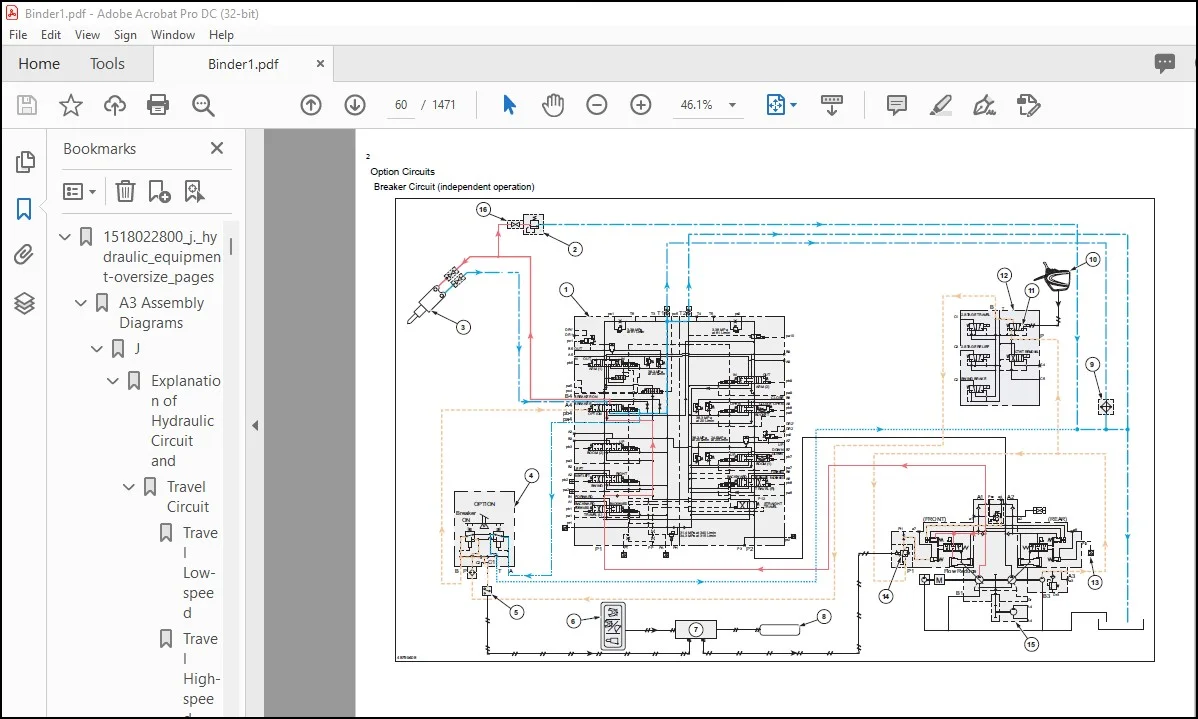
Option Circuits 60
Breaker Circuit (independent operation) 60
Double-acting Circuit (hydraulic fork) 62
Multi-purpose Circuit (breaker circuit) 64
Multi-purpose Circuit (2 pumps flow crusher) 66
2nd Option Circuit (hydraulic rotation fork) 68
1531771284_001_safety_470x3 71
SAFETY 71
SAFETY, GENERAL INFORMATION AND STANDARD TORQUE DATA 74
General Information 75
Safety 75
ROPS 78
ROPS Judgment Method 78
Standard Torque Data For Cap Screws And Nuts 83
Bolt and Nut Tightening 83
1531773709_002_a _lower_470x3 85
A LOWER 85
Specifications 89
470X3 89
Travel Lower Body 89
Main Equipment Table 90
470X3 90
Lower Component 90
Travel Unit 90
Take-up Roller 90
Upper Roller 90
Lower Roller 90
Recoil Spring 90
Shoe 91
Center Joint 91
Main Equipment Structure and Operation Explanation 92
Travel Motor 92
Travel motor operation explanation 92
Structure 92
Summary explanation of component parts 93
Rotary group 93
Parking Brake 93
Variable Capacity Mechanism Section 93
Overload Relief Valve 94
Brake Valve Section 95
Function 96
Motor operation 96
Parking Brake Operation 97
Operation of Variable Capacity Mechanism Section 98
Overload Relief Valve Operation 100
Brake Valve Operation 101
Port Diagram 105
Travel Motor 105
Center Joint 106
Basic Functions 107
Travel Speed Selection 107
Travel Alarm 109
Removal and Installation of Track 111
Removal and Installation of Shoe Assembly 111
Removal of Shoe Assembly 111
Installation of Shoe Assembly 113
Removal and Installation of Shoe Plate 114
Removal of Shoe Plate 114
Installation of Shoe Plate 114
Precautions for Shoe Bolt Installation 115
Removal and Installation of Roller 116
Removal and Installation of Upper Roller 116
Removal of Upper Roller 116
Installation of Upper Roller 117
Assembly and Disassembly of Upper Roller 118
Configuration Diagram 118
Dimension Diagram 119
Jig Dimension Diagram 119
Disassembly Procedures 119
Assembly Procedures 121
Removal and Installation of Lower Roller 123
Removal of Lower Roller 124
Installation of Lower Roller 124
Assembly and Disassembly of Lower Roller 125
Configuration Diagram 126
Dimension Diagram 126
Jig Dimension Diagram 127
Disassembly Procedures 127
Assembly Procedures 129
Removal and Installation of Retractable Lower Frame 132
Removal of Retractable Lower Frame 132
Installation of Retractable Lower Frame 133
Removal and Installation of Drive Sprocket 134
Removal of Drive Sprocket 134
Installation of Drive Sprocket 135
Removal and Installation of Take-up Roller 136
Removal of Take-up Roller 136
Installation of Take-up Roller 137
Assembly and Disassembly of Take-up Roller 138
Configuration Diagram 139
Dimension Diagram 139
Jig Dimension Diagram 139
Disassembly Procedures 140
Assembly Procedures 141
Removal and Installation of Grease Cylinder 144
Removal of Grease Cylinder 144
Installation of grease cylinder 145
Assembly and Disassembly of Grease Cylinder 146
Configuration Diagram 146
Dimension Diagram 146
Jig Dimension Diagram 147
Disassembly Procedures 147
Assembly Procedures 147
Removal and Installation of Center Joint 149
Removal of Center Joint 149
Installation of Center Joint 151
Assembly and Disassembly of Center Joint 152
Configuration Diagram 153
Dimension Diagram 154
Jig Dimension Diagram 155
Disassembly Procedures 155
Assembly Procedures 156
Removal and Installation of Travel Motor 160
Removal of Travel Motor 160
Installation of Travel Motor 162
Assembly and Disassembly of Travel Motor 165
Tools for Assembly and Disassembly 165
Standard tools 165
Secondary Materials 165
Special Tool (jig) 166
Measurement Device 169
Motor Disassembly Procedures 170
Precautions before motor disassembly 170
Tightening Torque 170
Disassembly procedure 171
Removal of supplied valves 171
Disassembly of motor 171
Disassembly of overload relief valve 175
Reduction gear disassembly procedures 175
Disassembly preparations 175
Disassembly procedure 176
Installation to Receiving Platform Of Reduction Gear (unit) 176
Removal of Reduction Gear Cover 176
Removal of carrier 1 assembly 176
Removal of carrier 2 assembly 177
Removal of housing assembly 177
Disassembly of Housing Assembly 178
Removal of floating seal from motor 179
Disassembly of carrier 1 assembly 179
Disassembly of Carrier 2 Assembly 179
Maintenance standards 181
Motor Parts Maintenance Standards 181
Reduction gear parts maintenance standards 183
Inspection prior to reassembly 183
Thrust washer 183
Gears 184
Bearing 184
Floating seal 184
Parts Maintenance 184
Assembly of motor 185
Precautions before Motor Assembly 185
Assembly procedure 185
Motor Assembly Procedures 185
Motor assembly procedure 189
Assembly of the Carrier 2 Assembly 189
Assembly of the carrier 1 assembly 190
Installation of bearing and floating seal 190
Assembly of the housing assembly 190
Determining the thickness of the angular bearing shim 191
Installation of housing assembly 192
Installation of Carrier 2 Assembly 193
Installation of carrier 1 assembly 193
Cover Attachment 194
Gear Oil Filling 194
Initial pre-conditioning operation 195
Drain charge 195
Performing initial operation (pre-conditioning operation) 195
Troubleshooting 196
General cautions 196
Causes of troubles and countermeasures 196
Structural diagram 199
Travel Motor 199
Reduction Gear 201
Maintenance Standards 203
Drive Sprocket 203
Take-up Roller 204
Upper Roller 205
Lower Roller 207
Track Shoe (grouser shoe) 208
Inspection Gauge 210
For Drive Sprocket 210
For Take-up Roller 210
For Upper Roller 211
For Lower Roller 211
Pressure Measurement and Adjustment Procedures 212
Main Pressure Measurement 212
B Travel Pressure Measurement 212
Drain Volume Measurement Procedures 213
Preparations 213
Travel Motor Drain Volume Measurement 213
Air Bleed Procedure 215
Travel Motor 215
1531773732_003_b _c _swing_unit_counterweight_470x3 217
B C SWING UNIT, COUNTERWEIGHT 217
Specifications 220
470X3 220
Upper Side Work System 220
Swing Units 221
Main Equipment Table 222
470X3 222
Upper Component 222
Swing Unit 222
Main Equipment Structure and Operation Explanation 223
Swing Motor 223
Swing Motor Operation Explanation 223
Hydraulic Motor Operation Explanation 223
Mechanical Brake Operation Explanation 223
Make-up Valve Operation Explanation 224
Relief Valve Operation Explanation (relief valve internal structure diagram) 224
Bypass Valve Operation Explanation (bypass valve internal structure diagram) 226
Swing motor internal diagram 227
Port Diagram 229
Swing Motor 229
Basic Functions 230
Swing Brake 230
Swing Lock 231
Swing Speed Limit 232
Free Swing (option) 233
Removal and Installation of Swing Unit 234
Removal of Swing Unit 234
Installation of Swing Unit 236
Assembly and Disassembly of Swing Motor 237
Causes of Trouble and Solutions 238
Maintenance Standard Table 240
Jig 241
Disassembly 241
Assembly 246
Swing Motor Internal Structural Diagram 253
Assembly and Disassembly of Swing Unit 255
Disassembly 255
Assembly 256
Assembly and Disassembly of Swing Reduction Gear 258
Disassembly 258
Assembly 260
Swing Reduction Gear Structure Diagram 266
Removal and Installation of Counterweight 268
Removal of Counterweight 268
Installation of Counterweight 269
Pressure Measurement and Adjustment Procedures 270
Main Pressure Measurement 270
C Swing Pressure Measurement 270
Drain Volume Measurement Procedures 271
Preparations 271
Swing Motor Drain Volume Measurement 271
Air Bleed Procedure 272
Swing Motor 272
1531773766_004_h _engine_470x3 273
H ENGINE 273
Specifications 278
470X3 278
Engine 278
Cooling System 278
Capacities, Filters 279
Coolant and Oil Capacities 279
Fuel Filter 279
Main Equipment Table 280
470X3 280
Engine-related 280
Engine 280
DPD 280
Air Cleaner (double element) 280
Radiator 281
Basic Functions 282
Fuel Gauge 282
Coolant Temperature Gauge 284
DPD Gauge 286
Fuel Economy Gauge 287
Neutral Start 288
Engine Start/Stop Control 289
Power-cut Delay 290
Preheating 291
Throttle 292
Engine Throttle Switch Position Detection 293
Idling Start 298
Auto Idle 299
One-touch Idle 300
Auto Warm Up 301
Quick Warm Up 302
Idling Stop 304
Idle up 305
Work Mode Control 306
Engine Emergency Stop 308
Coolant Level Reduction 308
Air Filter Clogged 309
Fuel Filter Clog 310
DPD Regeneration 310
Automatic Regeneration 312
Manual Regeneration 314
Optional Manual Regeneration 316
Hydraulic Assisting Load 318
Primary specifications 319
Function, Structure, and Operations 321
Symptom 374
Frequent Manual DPD Regeneration 374
DPD Regeneration Taking Excessively Long 375
Engine Start Problems 376
Engine Stalling 378
Engine Hunting, Rough Idling 380
Excess Amount of White Smoke in Exhaust Gas 381
Excess Amount of Black Smoke in Exhaust Gas 382
Abnormal Noise 382
Large fuel consumption 383
Large oil consumption 384
Engine Output Deficiency 385
Functional Inspection 387
Inspection of the scan tool power circuit system 387
Inspection of the starter circuit system 387
Compression pressure inspection 388
Inspection of the starting system 389
Inspection of the fuel system 390
Inspection of the air intake system 391
Inspection of the exhaust system 391
Inspection of EGR Control System 391
Inspection of the glow control system 392
DPD Function Inspection 393
OBD System Check 395
Inspection of the diagnostic light warning light illumination circuit system 396
Inspection of the monitor warning light blinking circuit system 396
Inspection of Scan Tool Power Supply System 397
Maintenance precautions 398
Removal and Installation of Engine Assembly 401
Removal of Engine Assembly 401
Installation of Engine Assembly 406
Removal and Installation of Fuel Cooler, Engine Intercooler, Radiator, and Oil Cooler 407
Removal and Installation of Fuel Cooler 407
Removal of Fuel Cooler 407
Installation of Fuel Cooler 407
Removal and Installation of Engine Intercooler 408
Removal of Intercooler 408
Installation of Inter Cooler 408
Removal and Installation of Radiator 409
Removal of Radiator 409
Installation of Radiator 412
Removal and Installation of Oil Cooler 412
Removal of Oil Cooler 412
Installation of oil cooler 414
Removal and Installation of Hydraulic Drive Fan 415
Removal of Hydraulic Drive Fan 415
Installation of Hydraulic Drive Fan 416
Removal and Installation of Turbocharger assembly 417
Turbocharger assembly Removal 417
Turbocharger assembly Installation 418
Removal and Installation of EGR valve 421
EGR valve Removal 421
EGR valve Installation 422
Removal and Installation of Engine Hood 426
Removal of Engine Hood 426
Installation of Engine Hood 427
Removal and Installation of Muffler 428
Removal of Muffler 428
Installation of Muffler 428
Removal and Installation of Cylinder head cover 429
Cylinder head cover Removal 429
Cylinder head cover Installation 429
Removal and Installation of Cylinder head 430
Cylinder head assembly Removal 430
Cylinder head assembly Disassembly 436
Cylinder head assembly Reassembly 439
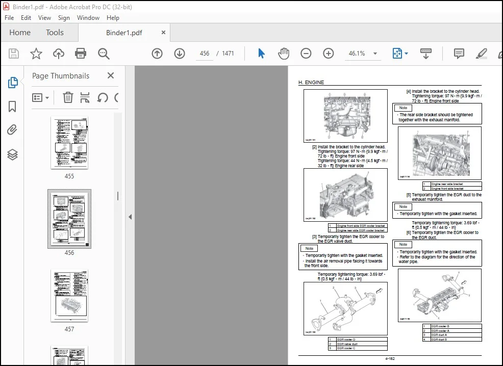
Cylinder head assembly installation 444
Cylinder head assembly Inspection 459
Removal and Installation of Cylinder block 466
Cylinder block Removal 466
Cylinder block installation 478
Cylinder block Inspection 507
Lubrication System 509
Removal and Installation of Oil pan 509
Oil pan Removal 509
Oil pan Installation 509
Removal and Installation of Oil level switch 509
Oil level switch Removal 509
Oil level switch Installation 510
Removal and Installation of Oil pump assembly 510
Oil pump assembly Removal 510
Oil pump assembly Disassembly 510
Oil pump assembly Reassembly 511
Oil pump assembly Installation 511
Oil pump assembly Inspection 512
Engine oil Inspection 512
Cooling System 514
Removal and Installation of Water pump assembly 514
Water pump assembly Removal 514
Water pump assembly Installation 515
Water pump assembly Inspection 519
Removal and Installation of Thermostat 520
Thermostat Removal 520
Thermostat Installation 522
Thermostat Inspection 526
Coolant Inspection 526
Removal and Installation of Overheat switch 528
Overheat switch Removal 528
Overheat switch Installation 528
Disassembly, Removal and Installation of DPD assembly 529
Disassembly of DPD Assembly 529
DPD assembly Reassembly 530
DPD assembly Inspection 532
Removal and Installation of Fuel Tank 534
Removal of Fuel Tank 534
Installation of fuel tank 536
Removal and Installation of Fuel supply pump 537
Fuel supply pump Removal 537
Fuel supply pump Installation 539
Removal and Installation of Common rail assembly 547
Removal of Common Rail Assembly 547
Common rail assembly Installation 548
Removal and Installation of Injector 551
Injector Removal 551
Injector Installation 554
Removal and Installation of Starter Motor 560
Removal of Starter Motor 560
Installation of Starter Motor 561
Removal and Installation of Alternator 562
Removal of Alternator 562
Installation of Alternator 562
Preheating System 563
Removal and Installation of Glow plug 563
Glow plug Removal 563
Glow plug Installation 564
Glow plug Inspection 567
Introduction to the trouble diagnosis 568
Removal and Installation of Fuel filter pressure sensor 576
Fuel filter pressure sensor Removal 576
Fuel filter pressure sensor Installation 577
Removal and Installation of Engine coolant temperature sensor 577
Engine coolant temperature sensor Removal 577
Engine coolant temperature sensor Installation 578
Engine coolant temperature sensor Inspection 578
Removal and Installation of CKP sensor 579
CKP sensor Removal 579
CKP sensor Installation 579
CKP sensor Inspection 579
Removal and Installation of CMP sensor 579
CMP sensor Removal 579
CMP sensor Installation 579
CMP sensor Inspection 580
Removal and Installation of Oil pressure sensor 580
Oil pressure sensor Removal 580
Oil pressure sensor Installation 580
Removal and Installation of Boost sensor 580
Boost sensor Removal 580
Boost sensor Installation 580
Removal and Installation of Boost temperature sensor 581
Boost temperature sensor Removal 581
Boost temperature sensor Installation 581
Removal and Installation of IMT sensor 581
IMT sensor Removal 581
IMT sensor Installation 581
Removal and Installation of Exhaust differential pressure sensor 582
Exhaust differential pressure sensor Removal 582
Exhaust differential pressure sensor Installation 583
Exhaust differential pressure sensor Inspection 583
Removal and Installation of Exhaust gas temperature sensor 584
Removal of Exhaust Gas Temperature Sensor 584
Exhaust gas temperature sensor Installation 584
Exhaust gas temperature sensor Inspection 585
Engine-side Diagnostic Trouble Code List 586
Troubleshooting – engine 589
Engine-side Trouble 589
Diagnostic Trouble Code 0016 Abnormally Correlation Between Crankshaft Position and Camshaft Position 589
Diagnostic trouble code 0045 Turbocharger Boost Pressure Control System Abnormality 590
Diagnostic Trouble Code 0087 Fuel Rail System Pressure Low Pressure Error 592
Diagnostic Trouble Code 0088 Fuel Rail System Pressure High Pressure Error 595
Diagnostic Trouble Code 0089 Fuel Rail Pressure Regulator Characteristic Error 597
Diagnostic Trouble Code 0091 Fuel Rail Pressure Regulator Control System Low Input 599
Diagnostic Trouble Code 0092 Fuel Rail Pressure Regulator Control System High Input 600
Diagnostic Trouble Code 0093 Fuel System Leak Detection 601
Diagnostic Trouble Code 0102 Mass Air Flow Sensor System Low Input 602
Diagnostic Trouble Code 0103 Mass Air Flow Sensor System High Input 603
Diagnostic Trouble Code 0112 Intake Temperature Sensor System Low Input 604
Diagnostic Trouble Code 0113 Intake Temperature Sensor System High Input 605
Diagnostic Trouble Code 0117 Engine Coolant Temperature Sensor System Low Input 606
Diagnostic Trouble Code 0118 Engine Coolant Temperature Sensor System High Input 607
Diagnostic Trouble Code 0122 Throttle Sensor System Low Input 608
Diagnostic Trouble Code 0123 Throttle Sensor System High Input 609
Diagnostic Trouble Code 0182 Fuel Temperature Sensor System Low Input 610
Diagnostic Trouble Code 0183 Fuel Temperature Sensor System High Input 610
Diagnostic Trouble Code 0192 Fuel Rail Pressure Sensor System Low Input 611
Diagnostic Trouble Code 0193 Fuel Rail Pressure Sensor System High Input 612
Diagnostic Trouble Code 0201 Injector First Cylinder System Error 613
Diagnostic Trouble Code 0202 Injector Second Cylinder System Error 615
Diagnostic Trouble Code 0203 Injector Third Cylinder System Error 616
Diagnostic Trouble Code 0204 Injector Fourth Cylinder System Error 618
Diagnostic Trouble Code 0205 Injector Fifth Cylinder System Error 619
Diagnostic Trouble Code 0206 Injector Sixth Cylinder System Error 621
Diagnostic Trouble Code 0217 Engine Coolant High Temperature Error 622
Diagnostic Trouble Code 0219 Engine High Rpm Error 623
Diagnostic Trouble Code 0234 Turbocharger High Boost Pressure Abnormality 624
Diagnostic Trouble Code 0237 Boost Sensor Circuit Low Input 625
Diagnostic Trouble Code 0238 Boost Sensor Circuit High Input 626
Diagnostic Trouble Code 0335 Crankshaft Position Sensor System Error 627
Diagnostic Trouble Code 0340 Camshaft Position Sensor System Error 629
Diagnostic Trouble Code 0380 Glow Plug System Error 630
Diagnostic Trouble Code 0404 EGR1 Control System Error 631
Diagnostic Trouble Code 0409 EGR1 Position Sensor System Error 632
Diagnostic Trouble Code 041C IMT Sensor System High Input 633
Diagnostic Trouble Code 041D IMT Sensor System Low Input 634
Diagnostic Trouble Code 0426 Pre-filtered Exhaust Gas High Temperature Error 634
Diagnostic Trouble Code 0427 Exhaust Temperature Sensor 1 System Low Input 635
Diagnostic Trouble Code 0428 Exhaust Temperature Sensor 1 System High Input 636
Diagnostic Trouble Code 042B Exhaust Gas High Temperature Error Before Oxidation Catalyst 637
Diagnostic Trouble Code 042C Exhaust Temperature Sensor 2 System Low Input 638
Diagnostic Trouble Code 042D Exhaust Temperature Sensor 2 System High Input 639
Diagnostic Trouble Code 0522 Oil Pressure Sensor System Low Input 640
Diagnostic Trouble Code 0523 Oil Pressure Sensor System High Input 641
Diagnostic Trouble Code 0560 System Voltage Error 642
Diagnostic Trouble Code 0563 System Voltage High Input 643
Diagnostic Trouble Code 0601 Control Module Memory Checksum Error 644
Diagnostic Trouble Code 0602 Control Module Program Error 644
Diagnostic Trouble Code 0604 Control Module RAM Error 645
Diagnostic Trouble Code 0606 Control Module Processing Device Error 645
Diagnostic Trouble Code 060B Control Module A/D Converter Processing System Characteristics Error 646
Diagnostic Trouble Code 0638 Throttle Actuator Control System Characteristic Error 646
Diagnostic Trouble Code 0641 Sensor Voltage System Error 647
Diagnostic Trouble Code 0651 Sensor Voltage System Error 649
Diagnostic Trouble Code 0685 ECM Main Relay Control System Low Input 650
Diagnostic Trouble Code 0687 ECM Main Relay Control System High Input 651
Diagnostic Trouble Code 0697 Sensor Voltage System Error 651
Diagnostic Trouble Code 1062 Fuel Rail Pressure Regulator PCV1 Drive Circuit Abnormality 652
Diagnostic Trouble Code 1063 Fuel Rail Pressure Regulator PCV2 Drive Circuit Abnormality 653
Diagnostic Trouble Code 1093 Fuel Rail Pressure Low Pressure Error 653
Diagnostic Trouble Code 1112 Boost Temperature Sensor System Low Input 655
Diagnostic Trouble Code 1113 Boost Temperature Sensor System High Input 655
Diagnostic Trouble Code 1261 Injector Group 1 Voltage Control System Error 656
Diagnostic Trouble Code 1262 Injector Group 2 Voltage Control System Error 657
Diagnostic Trouble Code 1293 Fuel Filter Pressure Sensor System Low Input 657
Diagnostic Trouble Code 1294 Fuel Filter Pressure Sensor System High Input 658
Diagnostic Trouble Code 1404 EGR Close Position Characteristic Error 659
Diagnostic Trouble Code 140A EGR2 Control System Characteristic Abnormality 660
Diagnostic Trouble Code 140B EGR2 Position Sensor System Error 660
Diagnostic Trouble Code 140C EGR2 Close Position Characteristic Error 662
Diagnostic Trouble Code 1455 DPD Restriction 2 663
Diagnostic Trouble Code 1471 DPD Regeneration Error 664
Diagnostic Trouble Code 1621 Control Module EEPROM Error 666
Diagnostic Trouble Code 1655 Sensor Voltage System Error 667
Diagnostic Trouble Code 2146 Injector Group 1 Supplied Voltage System Error 668
Diagnostic Trouble Code 2149 Injector Group 2 Supplied Voltage System Error 669
Diagnostic Trouble Code 2228 Atmospheric Pressure Sensor System Low Input 671
Diagnostic Trouble Code 2229 Atmospheric Pressure Sensor System High Input 672
Diagnostic Trouble Code 2295 Fuel Rail Pressure Regulator 2 PCV2 Drive Circuit Disconnection/Short 673
Diagnostic Trouble Code 2296 Fuel Rail Pressure Regulator 2 PCV2 Drive Circuit Power Supply Short Circuit 674
Diagnostic Trouble Code 242F DPD Restriction 674
Diagnostic Trouble Code 2452 DPD Differential Pressure Sensor System Error 676
Diagnostic Trouble Code 2453 DPD Differential Pressure Sensor System Characteristic Error 678
Diagnostic Trouble Code 2454 DPD Differential Pressure Sensor System Low Input 679
Diagnostic Trouble Code 2455 DPD Differential Pressure Sensor System High Input 680
Diagnostic Trouble Code 2456 DPD Differential Pressure Sensor Learning Position Error 681
Diagnostic Trouble Code 2458 DPD Regeneration Time Error 682
Diagnostic Trouble Code 0001 CAN Bus Communication Error 684
Diagnostic Trouble Code 0073 Control Module Communication Error 685
Diagnostic Trouble Code 0101 TCM Communication Error 686
Diagnostic Trouble Code 0110 Turbocharger Control Module Communication Error 687
Data Reference Values 689
Non-operational P rotation 689
1531773809_005_j _hydraulic_equipment_pump_operation_system_valve_470x3 691
J HYDRAULIC EQUIPMENT (PUMP, OPERATION SYSTEM VALVE) 691
Specifications 696
470X3 696
Operating Device 696
Hydraulic Equipment 697
Hydraulic Device 697
Control Valve and Cylinder 697
Capacities, Filters 697
Hydraulic Filters 697
Main Equipment Table 698
470X3 698
Hydraulic Device 698
Hydraulic Pump 698
Control-related 698
Control Valve 698
Solenoid Valve (5 stack) 699
Valve for Left/Right Operations 699
Remote Control Valve for Travel Operations 699
Remote Control Valve Characteristic Diagram 700
Operation Remote Control Valve Control Diagram 700
Travel Remote Control Valve Control Diagram 701
Cushion Valve (heat circuit, with shuttle valve) 701
Selector Valve (option) 701
Basic Functions 702
Oil Temperature Gauge 702
Static Horsepower Control 703
Pressure Boost Control 704
Swing Relief Cut 706
Boom Down Energy Save 707
Auto Energy Save 708
Stroke Control 708
Feed Pump Automatic Stop 710
Hydraulic Oil Filter Clog 711
Pump Horsepower Cut Control 713
Pump Horsepower Boost Control 716
Solenoid Sticking Prevention 717
Hot Shutdown Warning 718
Option line control 719
Option line control 723
Breaker Mode 725
Crusher Mode 725
Port Diagram 726
Hydraulic Pump (standard model) 726
Control Valve 727
Relief Valve 727
5 Stack Solenoid Valve 730
2 Stack Solenoid Valve 731
Remote Control Valves (upper, travel) 732
Remote Control Valves (left-right) 732
Remote Control Valve (travel) 732
Reducing Valve (3 stack) 733
Cushion Valve 733
2-way Selector Valve 734
Direction Valve 734
Relief Valve (electromagnetic proportional) 735
Manifold Under Cab 735
Manifold (accumulator section) 736
Manifold 736
Hydraulic Device 737
Pump P-Q Diagram 737
Main Equipment Structure and Operation Explanation 738
Hydraulic Pump 738
Structure and Operation Explanation 738
Hydraulic Pump Internal Structure Diagram 739
Overall view 739
Drive Shaft Front Side 739
Drive Shaft Rear Side 740
Part Table 741
Gear Pump 742
Gear Pump Internal Structure Diagram 742
Structure and Operation Explanation 744
Control Valve 745
Basic configuration 745
Operation 745
5 Stack Solenoid Valve Operation Explanation 780
External Shape Diagram and Component Parts 780
Operation Explanation 781
Upper Pilot Valve (remote control valve) 782
Structure 782
Function 782
Operation 783
Structural Diagram 786
Travel Pilot Valve (remote control valve) 787
Operation 787
Pressure Reduction Valve Section 788
Operating Section Damping Mechanism Section 788
Structural Diagram 791
Cushion Valve 792
Structure 792
Operation Explanation 793
Pressure Bleeding Operations 797
Removal and Installation of Hydraulic Tank 798
Removal of Hydraulic Oil Tank 798
Installation of Hydraulic Oil Tank 801
Removal and Installation of Hydraulic Pump 802
470X3 802
Removal of Hydraulic Pump 802
Installation of Hydraulic Pump 803
Removal and Installation of Pump Coupling 806
Removal of Pump Coupling 806
Installation of Pump Coupling 807
Removal and Installation of Control Valve 809
Removal of Control Valve 809
Installation of Control Valve 811
Removal and Installation of Pilot Blocs 814
Removal and Installation of Travel Remote Control Valve 815
Removal of Travel Remote Control Valve 815
Installation of Travel Remote Control Valve 816
Removal and Installation of Operation Remote Control Valve 818
Removal of Operation Remote Control Valve (Left) 818
Installation of Operation Remote Control Valve (Left) 820
Removal of Operation Remote Control Valve (right side) 822
Installation of Operation Remote Control Valve (right side) 824
Removal and Installation of 5 Stack Solenoid 826
Removal of 5 Stack Solenoid Valve 826
Installation of 5 Stack Solenoid Valve 827
Removal and Installation of Cushion Valve 829
Removal of Cushion Valve 829
Installation of Cushion Valve 830
Procedures for Assembly and Disassembly of Hydraulic Pump Main Unit 833
Tools 833
Disassembly Procedures 833
Assembly Procedures 835
Pump Main Unit Maintenance Standards 838
Replacement standards for worn parts 838
Standards for repairing cylinders, valve plates, and swash plates (shoe plates) 839
Tightening torque 839
Overall View 840
Attached diagram 1 pump assembly cross-section diagram 840
Drive Shaft Front Side 840
Drive Shaft Rear Side 841
Part Table 842
Regulator Assembly and Disassembly Procedures 844
Tools 844
Disassembly preparations 844
Disassembly procedures 844
Assembly procedures 846
Procedures for Assembly and Disassembly of Control Valve 849
Disassembly 849
Cautions for disassembly 849
Disassembly procedure 849
Removal of long cap and pull out of main spool 849
Disassembly of arm 1 parallel-tandem spool, neutral cut spool section 850
Disassembly of arm regeneration release valve section 850
Disassembly of load check valve section 851
Disassembly of antidrift valve section 851
Disassembly of relief valve 852
Disassembly of option section 852
Disassembly of straight travel signal control valve 852
Disassembly of other plugs 852
Disassembly of add-on section 852
Disassembly of valve housing union bolt 853
Cleaning 853
Inspection 853
Cautions for Assembly 853
Cautions for O-Ring handling 853
Cautions for spool handling 853
Adhesive Application Method (for male thread section and female thread section of parts requiring adhesion) 853
Procedure for assembly of sub-assembly 854
Assembly of spool assembly (main spool) 854
Assembly of arm 1 parallel-tandem spool assembly 854
Assembly of neutral cut spool assembly 854
Assembly of antidrift valve assembly 855
Procedure for assembly of control valve main unit 855
Assembly of relief valve 855
Assembly of load check valve 855
Assembly of antidrift valve 856
Assembly of option section 856
Assembly of arm regeneration release valve 856
Assembly of arm 1 parallel-tandem spool 856
Assembly of neutral cut spool 856
Assembly of main spool 856
Assembly of straight travel signal control valve 857
Assembly of add-on section 857
Assembly of other plugs 857
Internal Structure Diagram 858
Parts List 865
Relief valve 866
Procedures for assembly and disassembly of main relief valve 866
Procedures for assembly and disassembly of overload relief valve 867
Procedures for assembly and disassembly of low-pressure relief valve 867
Procedures for assembly and disassembly of add-on main relief valve 868
Relief valve adjustment 869
Installation 869
Run 869
Troubles and Countermeasures 869
Procedures for Assembly and Disassembly of Operation Remote Control Valve 871
Maintenance Procedures 871
Required Tools and Tightening Torque 871
Maintenance Standards 872
Disassembly Procedures 873
Assembly Procedures 875
Causes of Trouble and Countermeasures 878
Procedures for Assembly and Disassembly of Travel Remote Control Valve 882
Maintenance Procedures 883
Disassembly Procedures 883
Assembly Procedures 887
Causes of Trouble and Countermeasures 892
Assembly and Disassembly of Cushion Valve 895
Disassembly Procedures 895
Reverse Operation Spool Section 895
Check Plunger Section with Throttle 895
Shuttle Valve Section 895
Assembly Procedures 896
Reverse Operation Spool Section 896
Check Plunger Section with Throttle 896
Shuttle Valve Section 896
Written Materials 897
Pressure Measurement and Adjustment Procedures 899
Procedures for Pressure Measurement from the Monitor Display 899
Monitor and Switch Panel 899
Pressure Measurement Method 899
Operating Method 899
PROCEDURES FOR MEASURING HYDRAULIC OIL TEMPERATURE FROM THE MONITOR DISPLAY 900
Hydraulic Oil Temperature Measurement Method 900
Operating Method 900
Procedures for Pressure Measurement by Installing Pressure Gauge 901
Preparations 901
Items to prepare 901
Pressure Measuring Ports 902
Control Valve 904
Location of Relief Valves 904
Pressure Measurement Preparations 906
Pressure Measurement 907
Main Pressure Measurement 907
A Attachment Pressure Measurement 909
Boom-down pressure measurement 910
D Option Line Pressure Measurement 910
Pilot Pressure Measurement 910
Pressure Gauge Installation 910
Negative Control Pressure Measurement 911
Pressure Gauge Installation 911
Pressure Adjustment 912
Main Pressure Adjustment 912
Pressure Measurement and Adjustment Preparation Work 912
Main Relief Pressure Adjustment 913
Overload Relief Pressure Adjustment 914
Swing Relief Pressure Adjustment 915
Pilot Pressure Adjustment 916
Hydraulic Pump Flow Measurement Procedures 917
Preparations 917
Items to Prepare 917
Work Preparations 918
Flow Measurement 920
Air Bleed Procedure 921
Hydraulic Pump 921
Check 921
Hydraulic Equipment Layout 922
Overall view 923
PUMP CHAMBER HYDRAULIC EQUIPMENT LAYOUT 924
SWING BODY CENTER SECTION HYDRAULIC EQUIPMENT 925
HOUSING LEFT SIDE HYDRAULIC EQUIPMENT LAYOUT 926
LAYOUT OF HYDRAULIC EQUIPMENT IN CAB 927
1531773839_006_n _cab_470x3 929
N CAB 929
Removal and Installation of Operator’s Seat 932
Removal of Operator’s Seat 932
Installation of Operator’s Seat 932
Removal and Installation of Cab Assembly 933
Removal of Cab Assembly 933
Installation of Cab Assembly 937
Removal and Installation of Wiper 938
Removal of Wiper 938
Installation of wiper 938
Removal and Installation of Cab Front Glass 939
Removal of Cab Front Glass 939
Installation of Cab Front Glass 940
Removal and Installation of Right-side Window Glass 941
Removal of Right-side Window Glass 942
Installation of Right-side Window Glass 943
Removal and Installation of Door (Upper) Sash Glass 946
Removal of Door (Upper) Sash Glass 947
Installation of Door (Upper) Sash Glass 948
Window Lock Adjustment Procedures 951
Window Lock (front side) 951
Window Lock (rear side) 951
Tightening torque 953
1531773875_007_r _electrical_parts_470x3 955
R ELECTRICAL PARTS 955
Electrical and Engine Functions and Service Support 960
Basic Functions 961
Monitor Display Dimming 961
Eco Gauge 962
Diagnostic Trouble Code Indicator 963
Clock 963
Accessories 964
Working Light 964
Room lamp 965
Radio Mute 967
Wiper and Washer 968
Horn 969
Back/Side View Monitor 970
Precautions When Installing the Camera 970
Anti-theft 971
Enabling the anti-theft function 971
Password 971
Immobilizer Key 972
Battery Disconnect Switch 973
Reset 974
Half Reset/All Reset 974
Milli-amp List 975
Safety 977
Lever Lock 977
Battery save function 978
Alternator Power Generation Detection 979
Service Support 981
Screen Operations 981
Screen Display List 981
CHECK Screen List 982
MACHINE STATUS 982
FAULT HISTORY 986
WORK HISTORY 987
ENGINE HISTORY 989
HYDRAULIC HISTORY 993
PART NUMBER 995
List of Control Unit Screens 996
CONTROLLER A 997
CONTROLLER B 999
MONITOR 1002
ECM 1004
AIR CONDITIONER 1004
COMMUNICATION 1005
SETUP Screen List 1006
MACHINE SELECT 1006
PARAMETERS 1010
RESET Screen List 1012
Setting 1013
Model Selection 1013
Throttle Volume Default Setting Value 1018
Password Setting 1018
Clock Adjustment 1019
Parameter Setting 1020
Option Flow Setting 1022
Screen Brightness Setting 1023
Service Monitor 1025
How to get into “Service Screen” 1025
General Operation on Service Monitor 1025
Engine Service Monitor 1026
Service Monitor Structure 1026
ENGINE INFORMATION 1027
Data Confirmation 1027
Data Transfer (Copy) 1027
QR (INJECTOR) CODE 1029
Injector Number 1029
Screen Layout 1029
Data Source Selection 1030
Manual Input 1030
DEVICE TEST 1031
Common Rail Pressure Test 1031
Injector Balance Test 1032
Injector Forced Drive Test 1033
ECM Memory Clear 1033
DPD Slow Regeneration 1034
DPD Manual Regeneration 1035
DPD Automatic Regeneration 1036
EGR Valve Control Test (if equipped) 1036
VG Turbo Control Test 1037
Intake Throttle Control Test 1037
Turbo Boost Test 1038
Computer Explanation 1039
Connection Connector Pin Layout 1045
Computer A 1045
Computer B 1046
Monitor 1047
Sequence Circuit Diagram 1048
Code table 1048
Overall 1050
Block diagram 1052
Computer A 1052
Computer B 1053
ECM 1054
Monitor 1055
Air Conditioner 1056
Lever Lock 1057
Horn 1057
Working lights 1057
Option 1058
Other 1059
Electrical Symbol List 1060
Electrical Equipment Layout Diagram 1061
Main Unit Left Side Layout Diagram (radiator chamber) 1062
Engine Section Layout Diagram 1063
Main Unit Right Side Layout Diagram (pump chamber) 1066
Main Unit Center Section Layout Diagram 1068
Cab Layout Diagram 1 1069
Cab Layout Diagram 2 1071
Layout Around Operator Seat 1073
Stand Alone Parts Diagram 1074
Removal and Installation of Wiper Controller 1096
Removal of Wiper Controller 1096
Installation of wiper controller 1096
Removal and Installation of Wiper Motor 1097
Removal of Wiper Motor 1097
Installation of wiper motor 1098
Removal and Installation of Monitor 1099
Removal of Monitor 1099
Installation of Monitor 1100
ECM Replacement Procedure 1101
Removal and Installation of ECM 1102
Removal of ECM 1102
Installation of ECM 1102
Removal and Installation of Computer A 1103
Removal of Computer A 1103
Installation of Computer A 1103
Removal and Installation of Computer B 1104
Removal of Computer B 1104
Installation of Computer B 1104
Air Conditioner Overall Diagram 1105
Frame 1105
Cab 1108
Equipment Layout Diagram 1111
Circuit Diagram 1113
Air Conditioner Circuit Diagram 1113
Explanation of Functions 1115
Explanation of Control 1115
Air Mix Motor Actuator Control 1116
Blow Mode Motor Actuator Control 1116
Refresh/Recirculate Switch Motor Actuator Control 1117
Blower Amp Control 1118
Compressor Clutch Control 1120
COOLMAX Control and HOTMAX Control 1121
Abnormality Detection and Control after Abnormality Detected 1121
Monitor Mode 1125
Door Switch Control 1126
Actuator Inspection 1128
Air Mix Motor Actuator Inspection 1128
Refresh/Recirculate Switch Motor Actuator Inspection 1129
Mode Motor Actuator Inspection 1130
Self-diagnosis Function with Panel Display 1131
Abnormality Display and Self-check Procedures 1131
Abnormality Display Position 1131
Explanation of Abnormality Display 1131
Motor Actuator Abnormality 1131
Sensor Abnormality 1132
Explanation of Monitor Mode 1132
Monitor Mode Display Position 1132
Monitor Mode Display Operating Method 1133
Display Contents in Monitor Mode 1134
Air Conditioner Troubleshooting 1135
Part Function and Good/Poor Judgment 1140
Control Panel 1140
Blower Amp 1140
Relay 1141
Air Mix Actuator 1142
Refresh/Recirculate Actuator 1143
Blow Mode Actuator 1143
Evaporator Sensor 1144
Dual Pressure Switch 1144
Solar Radiation Sensor 1145
Inside Air Sensor 1146
Assembly and Disassembly of Unit 1147
Removal of Blower Unit 1147
Replacement of Blower Motor 1147
Replacement of Blower Amp 1147
Removal of Heater Core 1148
Removal of Heat Case Right/Left 1148
Replacement of Evaporator and Expansion Valve 1148
Installation of Evaporator Sensor 1149
Replacement of Motor Actuator 1149
Removal and Installation of Compressor 1150
Removal of Compressor 1150
Installation of Compressor 1150
Removal and Installation of Condenser 1151
Removal of Condenser 1151
Installation of Condenser 1152
Removal and Installation of Receiver Dryer 1153
Removal of Receiver Dryer 1153
Installation of Receiver Dryer 1154
Work Precautions 1155
Work Procedures 1156
Air Conditioner Refrigerant Filling is Divided into the “Vacuum Operation” and “Gas Filling Operation” 1156
Operation Chart 1156
Tools 1157
Filling Procedures 1158
Charging Hose Connection Positions 1158
Gauge Manifold Connection 1158
Vacuuming 1159
Gas Filling Operation, High-pressure Side 1160
Gas Filling Operation, Low-pressure Side 1160
1518022866_r _electrical_parts-oversize_pages 1163
A3 Assembly Diagrams 1165
R 1165
Electrical Connector Wiring Diagram 1165
Main Frame 1166
Cab Main Harness 1168
R 1173
Electrical Parts and Wiring Assembly Diagram 1173
Frame 1174
Engine and Pump 1176
Attachments 1178
Battery 1180
Cab 1182
1531774046_008_v _attachments_470x3 1185
V ATTACHMENTS 1185
Main Equipment Table 1188
470X3 1188
Backhoe Attachment 1188
Cylinder 1188
Maintenance Standards 1189
Attachment (backhoe) 1189
1 Boom and Swing Frame Installation Section 1190
2 Boom Cylinder and Swing Frame Installation Section 1191
3 Boom and Boom Cylinder Installation Section 1192
4 Boom and Arm Cylinder Installation Section 1193
5 Boom and Arm Installation Section 1194
6 Arm and Arm Cylinder Installation Section 1195
7 Arm and Bucket Cylinder Installation Section 1196
8 Arm and Arm Link Installation Section 1197
9 Bucket and Bucket Link Installation Section 1198
10 Bucket Link and Bucket Cylinder Installation Section 1199
11 Bucket and Arm Installation Section 1200
Removal and Installation of Bucket Cylinder 1201
Removal of Bucket Cylinder 1201
Installation of Bucket Cylinder 1203
Removal and Installation of Arm Cylinder 1205
Removal of Arm Cylinder 1205
Installation of Arm Cylinder 1207
Removal and Installation of Boom Cylinder 1210
Removal of Boom Cylinder 1210
Installation of Boom Cylinder 1212
Procedures for Operation/Assembly and Disassembly of Hydraulic Cylinder 1215
Specifications and Structure Diagram (including the assembly diagram and parts table) 1215
Basic functions 1215
Function of Each Location 1215
Cylinder Head Assembly 1215
Piston Assembly 1216
Pipe assembly 1217
Handling Precautions 1218
Precautions for Installing the Cylinder on the Machine Body 1218
Usage Cautions 1218
Maintenance and Inspection Cautions 1219
Maintenance Inspection and Service 1220
Trouble Diagnostics 1221
Storage Standards 1226
Storing Parts Individually (In principle, store indoors ) 1226
When Mounted on Vehicle Body 1226
Recommended Anti-rust Oil 1227
Assembly and Disassembly Procedures 1228
Preparations ····· Prepare the Following before Starting Disassembly 1228
General Work Precautions 1228
Maintenance Standards 1228
Inspection after Assembly 1228
Required Tool 1229
General Tool 1229
Wrench Assembly (U1) 1231
Piston Ring Expander 1232
Bushing Tool Kit 1232
Disassembly Procedures 1233
Drain the Oil 1233
Secure the Cylinder 1233
Removal of Cylinder Head 1233
Pull out the Piston Rod 1233
Fasten the Piston Rod 1234
Remove the Piston Nut 1234
Removal of Piston etc 1234
Disassembly of the Retraction Side Cushion Ring 1235
Remove the Piston Seal 1235
Disassembly of the Buffer Ring 1235
Disassembly of U-ring and Wiper Ring 1235
Removal of O-ring and Backup Ring 1235
Disassembly of Bushing 1235
Removal of Pin Bushing 1236
Cleaning and Storage 1236
Assembly Procedures 1236
Assembly of Piston Rod Assembly 1236
Assembly of Piston Assembly 1236
Piston Rod Assembly 1237
Installation of Pin Bushing 1239
Replacement of Seals 1239
Assembly of Cylinder Head Assembly 1240
Assembly of Piston Assembly 1240
Insertion of Piston Rod into the Tube 1241
Cylinder Head Tightening 1241
Installation of Line 1241
Assembly of Piston Rod Assembly 1242
Assembly of Piston Assembly 1242
Piston Rod Assembly 1243
Structural Diagram 1247
Boom Cylinder 1247
Arm Cylinder 1249
Bucket Cylinder 1251
Port Diagram 1253
HBCV 1253
Removal and Installation of HBCV 1255
Removal and Installation of Arm HBCV 1255
Removal of Arm HBCV 1255
Installation of Arm HBCV 1255
Removal and Installation of Boom HBCV 1256
Removal of Boom HBCV 1256
Installation of Boom HBCV 1257
Air Bleed Procedure 1259
HBCV 1259
Boom Cylinder HBCV 1259
Arm Cylinder HBCV 1260
Removal and Installation of Bucket 1261
Removal of Bucket 1261
Installation of Bucket 1261
Removal and Installation of Bucket Link 1263
Removal of Bucket Link 1263
Installation of Bucket Link 1264
Removal and Installation of Arm 1265
Removal of Arm 1265
Installation of Arm 1266
Removal and Installation of Boom 1267
Removal of Boom 1267
Installation of Boom 1269
1531774075_009_z _other_470x3 1273
Z OTHER 1273
Specifications 1277
470X3 1277
ENGINE 1277
HYDRAULIC SYSTEM 1277
HYDRAULIC CONTROLS 1278
ELECTRICAL SYSTEM 1278
OPERATOR ENVIRONMENT 1279
UNDERCARRIAGE 1280
MASS 1280
DIGGING FORCE (with 2 0 m3 Sumitomo Bucket) (ISO 6015) 1280
DIMENSIONS 1281
WORKING RANGES 1282
SYSTEM FLUID CAPACITIES AND SPECIFICATIONS 1283
Arm Dimension 1284
470X3 1284
Standard Arm [3 38 m (11 0892 ft )] 1284
Short Arm [2 53 m (8 3005 ft )] 1286
Long Arm [4 00 m (13 1234 ft )] 1288
Ultra-long Arm [4 85 m (15 9121 ft )] 1290
Main Unit Weight 1292
470X3 1292
Divided Weight (standard specifications) 1292
Stand Alone Part Weight 1293
Shoe Weight (per side) 1293
Arm Weight 1293
Bolt Size and Torque Table 1294
Special Torque Settings 1294
Overall View 1299
470X3 1299
Standard Arm [3 38 m (11 0892 ft )] 1299
Short Arm [2 53 m (8 3005 ft )] 1300
Long Arm [4 00 m (13 1234 ft )] 1301
Ultra Long Arm [4 85 m (15 9121 ft )] 1302
470X3 Retract Lower Specification 1303
Standard Arm [3 38 m (11 0892 ft )] 1303
Short Arm [2 53 m (8 3005 ft )] 1304
Long Arm [4 00 m (13 1234 ft )] 1305
Ultra Long Arm [4 85 m (15 9121 ft )] 1306
470X3 MASS Excavator 1307
Short Arm (8 30 ft) 1307
Short Arm (8 30 ft) Retract Lower Specification 1308
WORK RANGE DIAGRAM 1310
470X3 1310
Standard Arm [3 38 m (11 0892 ft )] 1310
Short Arm [2 53 m (8 3005 ft )] 1312
Long Arm [4 00 m (13 1234 ft )] 1314
Ultra Long Arm [4 85 m (15 9121 ft )] 1316
470X3 Retract Lower Specification 1318
Standard Arm [3 38 m (11 0892 ft )] 1318
Short Arm [2 53 m (8 3005 ft )] 1320
Long Arm [4 00 m (13 1234 ft )] 1322
Ultra Long Arm [4 85 m (15 9121 ft )] 1324
New Machine Performance Judgment Table 1326
Table of Standards 1326
Measurement Method 1329
Engine Speed 1329
Pressure in Each Section 1329
Cylinder Falling Amount 1329
Attachment Speed 1329
Swing Speed 1330
Swing (180°) Brake Angle 1330
Travel Speed 1331
Travel Deviation 1332
Travel Sprocket Speed 1333
Shoe Tension Amount 1333
Swing Ball Race Bearing Movement Amount and Bucket Tip Movement Amount 1333
FLUIDS AND LUBRICANTS 1335
HYDRAULIC FLUID 1335
Engine Oil 1335
FUEL 1335
Conditions applicable to diesel fuel 1335
Recommended Conditions That Can Be Applied To Diesel Fuel 1335
Main Unit-side Diagnostic Trouble Code List 1336
Main Unit-side Trouble 1338
Diagnostic Trouble Code: 7000 P1 Pressure Sensor Signal Abnormality 1338
Diagnostic Trouble Code: 7001 P2 Pressure Sensor Signal Abnormality 1340
Diagnostic Trouble Code: 7002 N1 Pressure Sensor Signal Abnormality 1342
Diagnostic Trouble Code: 7003 N2 Pressure Sensor Signal Abnormality 1344
Diagnostic Trouble Code: 7004 Bottom Pressure Sensor Signal Abnormality 1346
Diagnostic Trouble Code: 7006 Rod Pressure Sensor Signal Abnormality 1348
Diagnostic Trouble Code: 7020 Upper Pressure Sensor Signal Abnormality 1350
Diagnostic Trouble Code: 7021 Swing Pressure Sensor Signal Abnormality 1352
Diagnostic Trouble Code: 7022 Travel Pressure Sensor Signal Abnormality 1354
Diagnostic Trouble Code: 7023 Arm-in Pressure Sensor Signal Abnormality 1356
Diagnostic Trouble Code: 7040 Fuel Level Sensor Signal Abnormality 1358
Diagnostic Trouble Code: 7041 Oil Temperature Sensor Signal Abnormality 1360
Diagnostic Trouble Code: 7060 Boom Angle Sensor Signal Abnormality 1362
Diagnostic Trouble Code: 7061 Arm Angle Sensor Signal Abnormality 1364
Diagnostic Trouble Code: 7063 Return Filter Clog Switch Abnormality 1366
(Breaker specifications) 1366
(Other than breaker specifications) 1367
Diagnostic Trouble Code: 7065 Boom-up Pilot Pressure Sensor Signal Abnormality 1368
Diagnostic Trouble Code: 7067 Bucket-close Pilot Pressure Sensor Signal Abnormality 1370
Diagnostic Trouble Code: 7200 Swing Brake Solenoid Signal Abnormality 1372
Diagnostic Trouble Code: 7201 Travel High-speed Solenoid Signal Abnormality 1374
Diagnostic Trouble Code: 7202 Pressure Boost Solenoid Signal Abnormality 1376
Diagnostic Trouble Code: 7203 Travel Alarm Buzzer Signal Abnormality 1379
Diagnostic Trouble Code: 7204 Power Save Solenoid Signal Abnormality 1381
Diagnostic Trouble Code: 7206 Option Line Switchover Solenoid Signal Abnormality 1384
Diagnostic Trouble Code: 7207 Free Swing Solenoid Signal Abnormality 1386
Diagnostic Trouble Code: 7208 Fan Reverse Solenoid Signal Abnormality 1388
Diagnostic Trouble Code: 7212 Shut-off Solenoid Signal Abnormality 1390
Diagnostic Trouble Code: 7240 Pump Horsepower Proportional Valve Signal Abnormality 1392
Diagnostic Trouble Code: 7241 P1 Flow Control Proportional Valve Signal Abnormality 1394
Diagnostic Trouble Code: 7242 Fan Proportional Valve Signal Abnormality 1396
Diagnostic Trouble Code: 7246 2 Pumps Flow Solenoid Signal Abnormality 1398
Diagnostic Trouble Code: 7247 Boom-down Proportional Valve Signal Abnormality 1400
Diagnostic Trouble Code: 7248 Arm-in Proportional Valve Signal Abnormality 1402
Diagnostic Trouble Code: 7253 DPD Regeneration Request Output Signal Abnormality 1404
Diagnostic Trouble Code: 7254 Washer Output Abnormality 1406
Diagnostic Trouble Code: 7400 Abnormally High Coolant Temperature [(105°C (221 0°F) or higher)] 1408
Diagnostic Trouble Code: 7401 Abnormally High Coolant Temperature [ 110 °C ( 230 0 °F )or higher ] 1409
Diagnostic Trouble Code: 7404 Abnormally High Oil Temperature [98 °C (208 4 °F) or higher] 1410
Diagnostic Trouble Code: 7405 Abnormally High Boost Temperature [ 80 °C ( 176 0 °F )or higher ], 7406 Abnormally High Boost Temperature [ 90 °C ( 194 0 °F )or higher ] 1411
Diagnostic Trouble Code: 7420 Abnormally Low Alternator Voltage 1412
Diagnostic Trouble Code: 7421 Coolant Level Reduction 1414
Diagnostic Trouble Code: 7422 Abnormally Low Engine Oil Pressure 1415
Diagnostic Trouble Code: 7423 Air Cleaner Clogging 1416
Diagnostic Trouble Code: 7424 Return Filter Clogging (with breaker) 1417
Diagnostic Trouble Code: 7426 Fuel Filter Clogging 1 1418
Diagnostic Trouble Code: 7427 Fuel Filter Clogging 2 1419
Diagnostic Trouble Code: 7601 Monitor Communication Abnormality 1420
Diagnostic Trouble Code: 7602 ECM Communication Abnormality 1421
Diagnostic Trouble Code: 7605 ECM Mismatch 1422
Diagnostic Trouble Code: 7606 EEPROM Data Abnormality 1423
Diagnostic Trouble Code: 7607 Computer C Communication Abnormality 1424
Diagnostic Trouble Code: 7608 Camera Abnormality 1425
Diagnostic Trouble Code: 7609 EEPROM (B) Data Abnormality 1427
Diagnostic Trouble Code: 7610 EEPROM (C) Data Abnormality 1428
Diagnostic Trouble Code: 7611 Computer A Communication Abnormality 1429
Diagnostic Trouble Code: 7612 Air Conditioner Communication Abnormality 1430
Diagnostic Trouble Code: 7613 Monitor Communication CAN Abnormality 1431
Diagnostic Trouble Code: 7614 Air Conditioner Panel Mismatch 1432
List of special tools 1433
NUMERICAL VALUE CONVERSION TABLE 1433
Unit conversion rate 1433
Length 1433
Area 1435
Volume 1436
Weight 1438
Pressure 1439
Torque 1440
Temperature 1441
A 1444
Travel Motor Special Tool 1444
470X3 1444
Take-up Roller Special Tool 1451
470X3 1451
Upper Roller Special Tool 1452
470X3 1452
Lower Roller Special Tool 1453
470X3 1453
Grease Cylinder Special Tool 1453
470X3 1453
C 1454
Swing Motor Special Tool 1454
470X3 1454
H 1456
Engine Oil Filter Special Tool 1456
470X3 1456
Fuel Filter Special Tool 1456
470X3 1456
Injector Special Tool 1457
470X3 1457
Circuit Test Special Tool 1457
250X3/300X3/350X3/470X3 1457
Cylinder Head Special Tool 1458
210X3/250X3/350X3/470X3 1458
Head Bolt Special Tool 1460
210X3/250X3/350X3/470X3 1460
Valve Spring Special Tool 1460
210X3/250X3/350X3/470X3 1460
J 1462
Remote Control Valve Special Tool 1462
470X3 1462
R 1464
Gas Filling Special Tool 1464
470X3 1464
V 1465
Attachment Special Tool (for Cylinder Assembly) 1465
Special Jigs Part Number List 1465
Attachment Special Tool (Other) 1467
470X3 1467
1536867221_001a_electrical470x3_page1 1468
1536867234_001a_electrical470x3_page2 1469
1536867243_001b_electrical470x3_page1_remotecare 1470
1536867257_002_hydraulic470x3_page1 1471
PLEASE NOTE:
- This is the SAME exact manual used by your dealers to fix your vehicle.
- The same can be yours in the next 2-3 mins as you will be directed to the download page immediately after paying for the manual.
- Any queries / doubts regarding your purchase, please feel free to contact [email protected]
S.V