Linkbelt 4HK1, 6HK1 Tier III Engine Mechanical Workshop Manual – PDF DOWNLOAD
Original price was: $86.95.$28.95Current price is: $28.95.
Linkbelt 4HK1, 6HK1 Tier III Engine Mechanical Workshop Manual – PDF DOWNLOAD
Description
Linkbelt 4HK1, 6HK1 Tier III Engine Mechanical Workshop Manual – PDF DOWNLOAD
FILE DETAILS:
Linkbelt 4HK1, 6HK1 Tier III Engine Mechanical Workshop Manual – PDF DOWNLOAD
Language : English
Pages : 314
Downloadable : Yes
File Type : PDF
Size: 12.1 MB
IMAGES PREVIEW OF THE MANUAL:
DESCRIPTION:
Linkbelt 4HK1, 6HK1 Tier III Engine Mechanical Workshop Manual – PDF DOWNLOAD
ISUZU DIESEL ENGINE (4HK1, 6HK1)
Precautions on Service Work
Matters that require attention in terms of maintenance
To prevent damage to the engine and ensure reliability of its performance, pay attention to the following in maintaining the engine: When taking down the engine on the ground, do not make the bearing surface of the oil pan touch directly the ground. Use a wood frame, for example, to support the engine with the engine foot and the flywheel housing.
Because there is only a small clearance between the oil pan and the oil pump strainer, it can damage the oil pan and the oil strainer.
• When the air duct or air cleaner is removed, cover the air intake opening to prevent foreign matter from getting into the cylinder. If it gets into it, it can considerably damage the cylinder and others while the engine is operating.
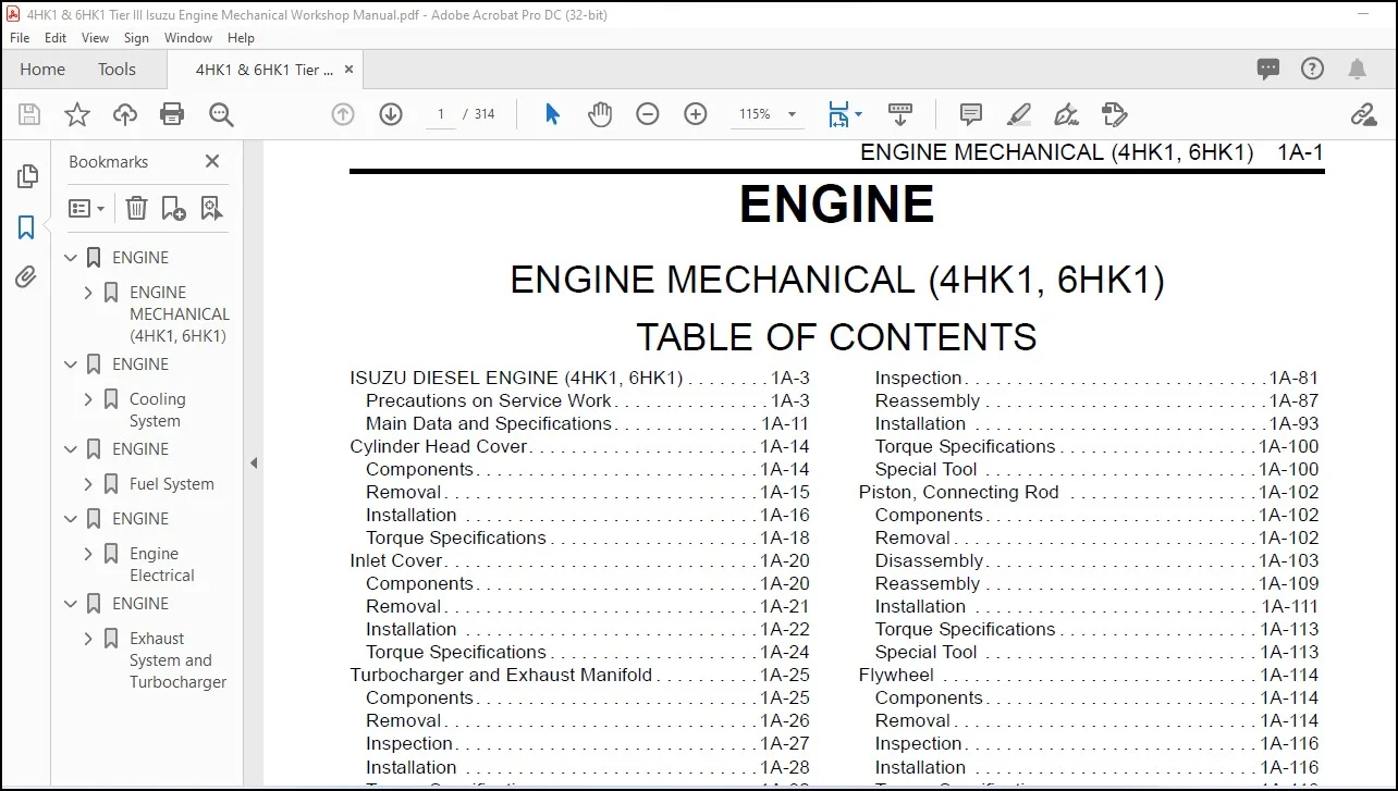
TABLE OF CONTENTS:
Linkbelt 4HK1, 6HK1 Tier III Engine Mechanical Workshop Manual – PDF DOWNLOAD
ENGINE 1
ENGINE MECHANICAL (4HK1, 6HK1) 1
ISUZU DIESEL ENGINE (4HK1, 6HK1) 3
Precautions on Service Work 3
Main Data and Specifications 11
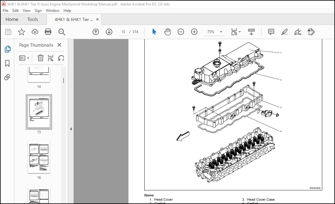
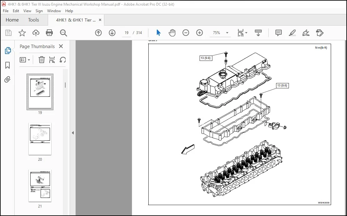
Cylinder Head Cover 14
Components 14
Removal 15
Installation 16
Torque Specifications 18
Inlet Cover 20
Components 20
Removal 21
Installation 22
Torque Specifications 24
Turbocharger and Exhaust Manifold 25
Components 25
Removal 26
Inspection 27
Installation 28
Torque Specifications 32
Timing Gear Train 35
Components 35
Removal 36
Inspection 38
Installation 40
Torque Specifications 51
Special Tool 52
Rocker Arm Shaft ASM 53
Components 53
Removal 53
Disassembly 54
Reassembly 56
Installation 57
Torque Specifications 58
Camshaft ASM 59
Components 59
Removal 60
Disassembly 61
Reassembly 63
Fixing torque 65
Special Tool 65
Installation 66
Torque Specifications 68
Valve Stem Seal, Valve Spring 69
Components 69
Removal 69
Inspection 70
Installation 71
Special Tool 73
Cylinder Head 74
Components 74
Removal 74
Disassembly 78
Inspection 81
Reassembly 87
Installation 93
Torque Specifications 100
Special Tool 100
Piston, Connecting Rod 102
Components 102
Removal 102
Disassembly 103
Reassembly 109
Installation 111
Torque Specifications 113
Special Tool 113
Flywheel 114
Components 114
Removal 114
Inspection 116
Installation 116
Torque Specifications 118
Special Tool 118
Front Cover 119
Components 119
Removal 120
Installation 121
Torque Specifications 123
Crankshaft Front Oil Seal 125
Components 125
Removal 125
Installation 127
Torque Specifications 132
Special Tool 132
Crankshaft Rear Oil Seal 133
Components 133
Removal 133
Installation 134
Special Tool 137
Crankshaft 138
Components 138
Removal 138
Disassembly 140
Reassembly 140
Inspection 140
Installation 145
Torque Specifications 149
Special Tool 149
Cylinder Block 151
Components 151
Removal 151
Inspection 152
Installation 153
Lubrication System 156
Precautions on Service Work 156
Function Check 157
Special Tool 158
Oil Port Cover ASM 159
Components 159
Removal 159
Installation 159
Oil Cooler 161
Components 161
Removal 162
Disassembly 163
Reassembly 163
Installation 164
Oil Pan 167
Components 167
Removal 167
Installation 167
Oil Pump 170
Components 170
Removal 170
Disassembly 171
Reassembly 171
Inspection 172
Installation 173
Oil Pressure Switch 177
Inspection 177
ENGINE 179
Cooling System 179
Cooling System 180
Precautions on Service Work 180
Function Check 183
A List of Defective Phenomena 185
Main Data and Specifications 185
Water Pump (4HK1) 186
Components 186
Removal 186
Inspection 187
Installation 188
Torque Specifications 189
Water Pump (6HK1) 190
Removal 190
Installation 192
Torque Specifications 194
Disassembly 195
Inspection and Repair 196
Reassembly 197
Thermostat 200
Components 200
Removal 200
Inspection 200
Installation 201
Drive Belt 202
Components 202
Inspection 202
Torque Specifications 204
ENGINE 205
Fuel System 205
Fuel System 206
Precautions on Service Work 206
Special Tool 213
Fuel Filter ASM 214
Components 214
Removal 214
Installation 214
Fuel Filter Element 215
Removal 215
Installation 215
Special Tool 215
Fuel Injector 216
Components 216
Removal 217
Installation 220
Torque Specifications 224
Special Tool 225
Fuel Supply Pump 226
Components 226
Removal 227
Installation 228
Torque Specifications 231
Common Rail 232
Components 232
Removal 233
Disassembly 235
Reassembly 236
Installation 236
Torque Specifications 239
ENGINE 241
Engine Electrical 241
Service Precautions 242
General Procedure 242
Charging System 243
General Description 243
Generator (4HK1) 245
Removal 245
Installation 246
Torque Specifications 246
Specifications 247
Connector terminal 247
Internal connections 247
Disassembly of generator 248
Inspection and repair of generator 249
Performance test 251
Handling of generator 252
Trouble and Action 253
Starting System 254
General Description 254
On-vehicle Service: Starting System 255
Starter (4HK1) 256
Removal 256
Installation 257
Torque Specifications 257
Main Data and Specifications 258
Connections (Nikko Electric Industry Co , Ltd) 259
Disassembly of starter 260
Inspection and repair of starter 261
Handling of starter 264
Trouble countermeasure 265
Preheating System 266
Glow Plug Replacement 266
Precautions on Service Work 267
A List of Defective Phenomena 267
Main Data and Specifications 268
Starter (6HK1) 269
Specifications 269
Sectional view (reference) 270
Output Characteristic (reference) 271
Disassembly and Inspection of Starter 272
Disassembly 273
Inspection and maintenance 274
Assembly of Starter 278
No Load Test 282
Specifications 282
Generator (6HK1) 283
Specifications 283
Charging Circuit 283
Structure 284
Disassembly and Inspection of Generator 285
Disassembly 286
Inspection 289
Assembly 291
Bench Testing 292
Trouble Diagnosis 293
Specifications 293
ENGINE 295
Exhaust System and Turbocharger 295
EGR System 296
Precautions on Service Work 296
EGR Valve and EGR Cooler 297
Components 297
Removal 297
Inspection 298
Installation 298
Torque Specifications 299
Exhaust System 300
A List of Defective Phenomena 300
Troubleshooting 300
Table of Specifications 301
Turbocharger Structured Diagram 302
Disassembly and Inspection of Turbocharger 303
Disassembly 304
Inspection 306
Assembly of Turbocharger 309
Assembly 310
Measurement Tool 314
Other Material 314
Customer Support: [email protected]
https://vimeo.com/768919989
PLEASE NOTE:
- This is not a physical manual but a digital manual – meaning no physical copy will be couriered to you. The manual can be yours in the next 2 mins as once you make the payment, you will be directed to the download page IMMEDIATELY.
- This is the same manual used by the dealers inorder to diagnose your vehicle of its faults.
- Require some other service manual or have any queries: please WRITE to us at [email protected]
S.V