Linkbelt 80 SPIN ACE TIER III Excavator Operation Manual PDF Download
$24.95
LINKBELT 80 SPIN ACE TIER III EXCAVATORS OPERATOR’S MANUAL – PDF DOWNLOAD
Description
LINKBELT 80 SPIN ACE TIER III EXCAVATORS OPERATOR’S MANUAL – PDF DOWNLOAD
FILE DETAILS:
LINKBELT 80 SPIN ACE TIER III EXCAVATORS OPERATOR’S MANUAL – PDF DOWNLOAD
Language : English
Pages : 162
Downloadable : Yes
File Type : PDF
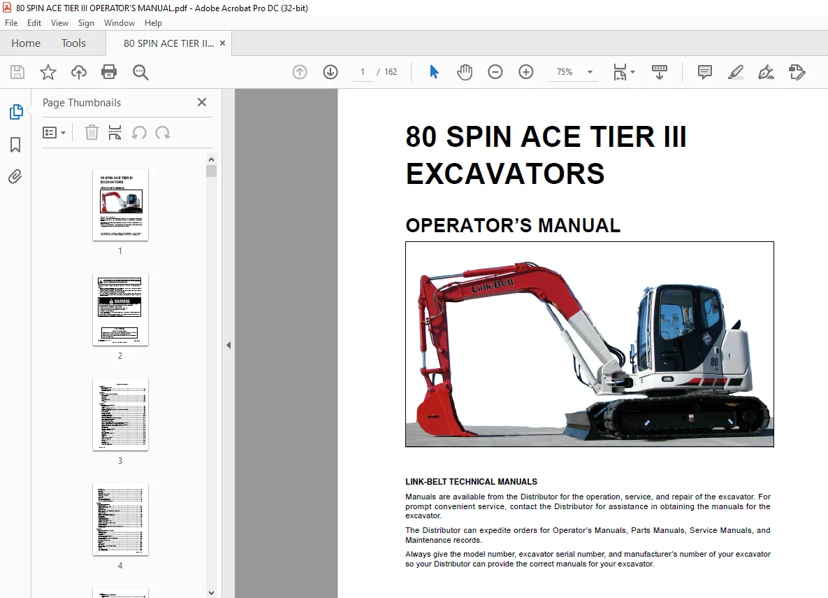
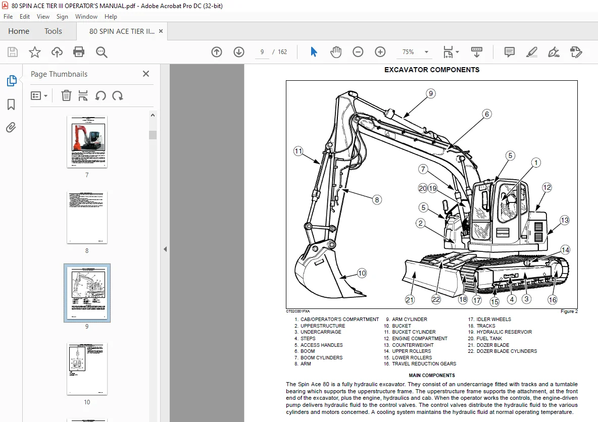
IMAGES PREVIEW OF THE MANUAL:
DESCRIPTION:
LINKBELT 80 SPIN ACE TIER III EXCAVATORS OPERATOR’S MANUAL – PDF DOWNLOAD
GENERAL INFORMATION:
- This excavator has been designed and built to the highest standards of quality. It conforms to all current safety regulations. However, the risk of accidents can never be completely excluded. That is why it is essential to observe elementary safety rules and precautions.
- Read this manual carefully, paying particular attention to the instructions concerning safety, operation and maintenance so as to avoid the risk of injury while operating or servicing the excavator.
- The standard attachments and tools of this excavator are designed to carry out all kinds of earthmoving and rehandling operations. If you want to use this excavator to handle a load (pipes, culverts, formwork, etc.), make sure that it is designed to carry out this kind of work.
- Do not use this excavator for any application or purpose other than those described in this manual. If the excavator is to be used for work involving the use of special attachments, accessories or equipment, consult your LBX
Link-Belt dealer in order to make sure that any adaptations or modifications made are in keeping with the excavator’s technical specifications and with prevailing safety requirements. - Any modification or adaptation which is not approved by the manufacturer may invalidate the excavator’s initial conformity with safety requirements.
- The excavator must undergo regular inspections, the frequency of which varies according to the type of use. Consult your LBX Link-Belt dealer.
Before permitting a new operator on this excavator, make sure:
1. That the operator has received the necessary training on how to operate the excavator correctly and safely in one of our training centers or from an approved organization.
2. That the operator has read and understood the instructions given in this manual. - Always keep this manual in the operator’s compartment (in the seat back, behind the operator’s seat). Make sure it is always complete and in good condition. If you wish to obtain extra copies, or a copy in Latin American Spanish, consult your LBX Link-Belt dealer.
- Your LBX Link-Belt dealer is at your disposal for any further information. They will also provide any after-sales service you may require, and genuine LBX Link-Belt spare parts, your guarantee of quality and match.
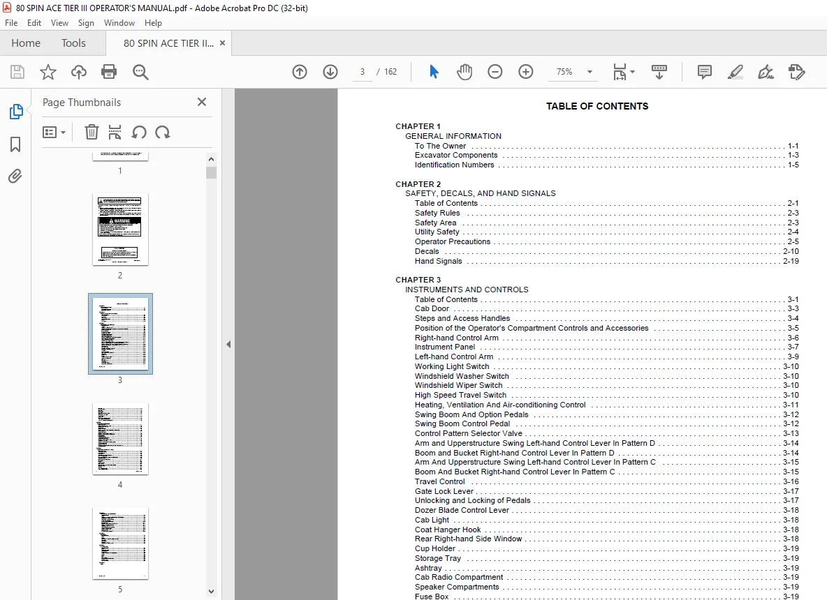
TABLE OF CONTENTS:
LINKBELT 80 SPIN ACE TIER III EXCAVATORS OPERATOR’S MANUAL – PDF DOWNLOAD
CHAPTER 1
GENERAL INFORMATION
To The Owner 1-1
Excavator Components 1-3
Identification Numbers 1-5
CHAPTER 2
SAFETY, DECALS, AND HAND SIGNALS
Table of Contents 2-1
Safety Rules 2-3
Safety Area 2-3
Utility Safety 2-4
Operator Precautions 2-5
Decals 2-10
Hand Signals 2-19
CHAPTER 3
INSTRUMENTS AND CONTROLS
Table of Contents 3-1
Cab Door 3-3
Steps and Access Handles 3-4
Position of the Operator’s Compartment Controls and Accessories 3-5
Right-hand Control Arm 3-6
Instrument Panel 3-7
Left-hand Control Arm 3-9
Working Light Switch 3-10
Windshield Washer Switch 3-10
Windshield Wiper Switch 3-10
High Speed Travel Switch 3-10
Heating, Ventilation And Air-conditioning Control 3-11
Swing Boom And Option Pedals 3-12
Swing Boom Control Pedal 3-12
Control Pattern Selector Valve 3-13
Arm and Upperstructure Swing Left-hand Control Lever In Pattern D 3-14
Boom and Bucket Right-hand Control Lever In Pattern D 3-14
Arm And Upperstructure Swing Left-hand Control Lever In Pattern C 3-15
Boom And Bucket Right-hand Control Lever In Pattern C 3-15
Travel Control 3-16
Gate Lock Lever 3-17
Unlocking and Locking of Pedals 3-17
Dozer Blade Control Lever 3-18
Cab Light 3-18
Coat Hanger Hook 3-18
Rear Right-hand Side Window 3-18
Cup Holder 3-19
Storage Tray 3-19
Ashtray 3-19
Cab Radio Compartment 3-19
Speaker Compartments 3-19
Fuse Box 3-19
Operator’s Seat 3-20
Windshield 3-23
Lower Front Window 3-25
Window-Breaker Hammer 3-25
Air Vents 3-25
Rear View Mirrors 3-26
Fuel Tank 3-26
Engine Hood 3-27
Side Doors 3-27
Right-hand Front Side Door 3-28
Rotating Beacon Cable 3-28
Towing Point 3-29
Lifting Eyes 3-29
Windshield Washer Reservoir 3-29
Tool Supply Valves (Optional) 3-30
Tool Flow Selector Valve (Optional) 3-30
CHAPTER 4
OPERATING INSTRUCTIONS
Table of Contents 4-1
Before Operating the Excavator 4-3
Operating the excavator 4-3
Run-in Period 4-4
Starting the Engine 4-4
Bringing the excavator up to Operating Temperature 4-6
Engine Operation 4-6
Stopping the Engine 4-7
Operating the Excavator in Cold Weather 4-8
Operating the Excavator in Hot Weather 4-8
Basic Operation 4-8
Excavator Travel 4-9
Transporting the Excavator 4-11
Handling the Excavator 4-14
Operating the Excavator In Water 4-14
Parking the Excavator 4-14
Operating the Excavator on Sloping Ground 4-15
Towing the Excavator 4-15
Operating the Bucket 4-16
Lowering The Attachment In The Event Of A Excavator Failure 4-16
Excavator Storage 4-20
CHAPTER 5
LUBRICATION, FILTERS, AND FLUIDS
Table of Contents 5-1
Servicing Instructions 5-3
Daily Inspections 5-4
Hourmeter 5-4
Lubrication Chart For 80 Spin Ace 5-5
Fluids and Lubricants 5-6
Fluid and Lubricant Capacities and Specifications 5-8
Lubrication Points 5-9
Greasing the Turntable Teeth 5-11
Fluid Levels 5-12
Engines 5-13
Cooling System 5-15
Fuel System 5-17
Releasing Pressure in the Hydraulic System 5-20
Hydraulic System 5-21
Air Filter 5-29
Swing Reduction Gear 5-32
Travel Reduction Gears 5-34
CHAPTER 6
MAINTENANCE AND ADJUSTMENTS
Table of Contents 6-1
Tracks 6-3
Checking the Condition of Rubber Tracks (If Equipped) 6-6
Replacing the Rubber Tracks 6-6
Track Rollers and Idler Wheels 6-8
Radiator and Oil Cooler 6-9
Fan and Alternator Drive Belt 6-10
Fuel Tank Filter 6-11
Inspecting and Cleaning the Excavator 6-11
Checking for Cylinder Leakage 6-11
Replacing a Bucket 6-12
Fire Extinguisher (Not Supplied) 6-13
Welding on the Excavator 6-13
Plastic and Resin Parts 6-13
Air Conditioning 6-14
Hardware Torque Inspection 6-16
CHAPTER 7
ELECTRICAL
Table of Contents 7-1
Fuses 7-3
Battery 7-5
Connecting One Or Two Booster Batteries 7-7
Alternator 7-7
Starter Motor 7-7
Replacing a Bulb 7-8
Adjusting The Working Lights 7-9
CHAPTER 8
SPECIFICATIONS
Table of Contents 8-1
Engine 8-3
Electrical Systems 8-3
Hydraulic System 8-3
Undercarriage 8-4
Capacity of Systems and Components 8-4
Weights 8-4
Boom 8-4
Arms 8-4
Digging Force 8-4
Excavator Overall Dimensions 8-5
Working Range 8-7
Lifting Capacities 8-9
CHAPTER 9
INDEX
Contact us: [email protected]
https://vimeo.com/891791665?share=copy
S.S